TR20F - Tapis de course SportsArt - Notice d'utilisation et mode d'emploi gratuit
Retrouvez gratuitement la notice de l'appareil TR20F SportsArt au format PDF.

Questions des utilisateurs sur TR20F SportsArt
0 question sur cet appareil. Repondez a celles que vous connaissez ou posez la votre.
Poser une nouvelle question sur cet appareil
Téléchargez la notice de votre Tapis de course au format PDF gratuitement ! Retrouvez votre notice TR20F - SportsArt et reprennez votre appareil électronique en main. Sur cette page sont publiés tous les documents nécessaires à l'utilisation de votre appareil TR20F de la marque SportsArt.
MODE D'EMPLOI TR20F SportsArt
TABLE OF CONTENTS
Introduction
- Important Safety Instructions.... 1
- Assembling Your Treadmill.... 4
Installation Requirements.... 4
List of Parts.... 4 - Treadmill Assembly.... 6
Step by Step Instructions.... 6 - Connect To Power.... 10
- TR20F Electronic Display.... 11
Electronics Display Layout.... 11
Display Features.... 12
Programs.... 14 - Guideline For Exercise.... 18
- Adjust The Running Belt.... 19
- Belt Adjustment Procedure.... 20
- Folding And Unfolding The Treadmill.... 22
- Floor Level Adjustment.... 23
- Trouble Shooting.... 24
Error Messages.... 24
How to relieve the ERR 7 restriction? 24 - Main Fuse Failure.... 25
- Wiring Schematic.... 26
Your SportsArt treadmill was designed and built for optimum safety. However, certain precautions apply whenever you use your treadmill.
Please read the entire manual before assembly and operation. Also, please note and save the following safety instructions:
IMPORTANT SAFETY INSTRUCTIONS
DANGER - To reduce the risk of electric shock:
Improper connection of the equipment-grounding connector can result in a risk of electric shock. Check with a qualified electrical or service person if you are in doubt as to whether the treadmill is properly grounded. Do not modify the plug provided with treadmill, if it doesn't fit the outlet, get the proper outlet installed by a qualified technician.
Always unplug this treadmill from the electrical outlet immediately after using and before cleaning.
WARNING - To reduce the risk of burns, fire, electric shock, or injury to persons:
1) The treadmill should never be left unattended when plugged in. Unplug from outlet when not in use, and before putting on or taking off parts.
2) Do not operate under blanket or pillow. Excessive heating can occur and cause fire, electric shock, or injury to persons.
3) Close supervision is necessary when this treadmill is used near children, invalids, or disabled persons.
4) Use this treadmill only for its intended use as described in this manual. Do not use attachments not recommended by the manufacturer.
5) Never operate this treadmill if it has a damaged cord or plug, if it is not working properly, if it has been dropped or damaged, or dropped into water. Return the treadmill to a service center for examination and repair.
6) Do not carry this treadmill by supply cord or use cord as a handle.
7) Keep the cord away from heated surfaces.
8) Never operate the treadmill with the air openings blocked. Keep the air openings free of lint, hair, and the like.
9) Never drop or insert any object into any opening.
10) Do not use outdoors.
11) The weight limit for this treadmill is 115 kgs. (250 lbs)
12) Do not operate where aerosol (spray) products are being used or where oxygen is being administered.
13) To disconnect, turn all controls to the off position, then remove plug from outlet.
14) Assemble and operate the treadmill on a solid, level surface. Keep the area behind the treadmill clear.
15) Never allow children on or near the treadmill. The running belt will not stop immediately if any object becomes caught in the belt or rollers.
16) Keep hands away from moving parts.
17) Wear proper workout clothing: Do not wear loose clothing. Do not wear shoes with leather soles or high heels. Tie back all long hair.
18) Straddle the machine with your feet on the right and left staging platform before starting the running belt.
19) Work within your recommended exercise level, do NOT work to exhaustion.
20) If you feel any pain or abnormal, STOP YOUR WORKOUT and consult your physician immediately.
21) Connect this treadmill to a properly grounded outlet only.
22) Always use the safety cord when operating the treadmill.
23) Please be cautious running belt must stop completely and incline must set to 0% before folding.
The Treadmill is designed for your use and enjoyment. Please follow the above safety instructions and using good judgment and common sense.
SPORTSART TR20F TREADMILL
INTRODUCTION
Congratulations on purchasing one of the finest piece of exercise equipment on the market today, the SportsArt TR20F treadmill. The TR20F is designed with the end user in mind and constructed of high quality materials and designed for years of trouble-free use.
Before using your SportsArt TR20F treadmill, we recommend that you familiarize yourself with this Owner's Manual. Whether you are a first time user of a treadmill or a seasoned "PRO", understanding the correct use of the equipment will enhance your ability to achieve your exercise goals safely and successfully.
Treadmill profile:
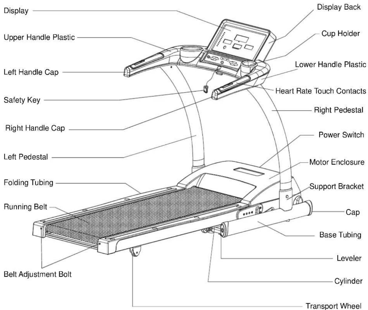
text_image
Display Upper Handle Plastic Left Handle Cap Safety Key Right Handle Cap Left Pedestal Folding Tubing Running Belt Belt Adjustment Bolt Display Back Cup Holder Lower Handle Plastic Heart Rate Touch Contacts Right Pedestal Power Switch Motor Enclosure Support Bracket Cap Base Tubing Leveler Cylinder Transport WheelASSEMBLING YOUR TREADMILL
Installation Requirements
Thank you for purchasing a SportsArt Fitness product. For proper installation please read and follow the instructions. If the treadmill is not assembled properly, you could void the SportsArt Fitness Limited Warranty.
If there are any parts or tools that are missing please contact your dealer immediately.
Caution: To ensure safety to yourself and the treadmill, we recommend you drop the sides of the box and slide the treadmill from the box rather than lifting.
List of Parts
Before assembling your treadmill, make sure that you have all following items:
- One safety key
- One fuse 15A(110v) / 10A(220v)
- One screwdriver for power connection
- One hex allen wrench(M6) with T handle for pedestal assembly
- One hex allen wrench(M4) with T handle for display assembly
- Two flat caps for pedestal assembly
- Two curved caps for pedestal assembly
Please see the part illustrations below

text_image
① Left Pedestal ② Right Pedestal ③ Handle ④ DisplayTREADMILL ASSEMBLY
Step by Step Instructions
The important spare parts are placed into the grid of styrofoam. When you remove the treadmill from its box, first check to make sure all of parts are present before you discard the styrofoam. Thoroughly read the assembly instructions before you begin.
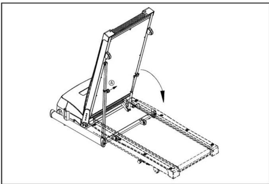
- Tilt up the walk deck as shown until you hear a click sound from knob Ⓐ, and make sure the walk deck will not slide down. Please also inspect the running belt and confirm that the belt is appropriately located between the two belt alignment guides under the back of treadmill as shown in figure Ⓑ.

natural_image
Technical line drawing of a mechanical device with labeled components A and B, showing a rotating mechanism (no text or symbols beyond labels)Fig.1
- Pull out the knob Ⓐ to slide down the walk deck gradually.
natural_image
Technical line drawing of a treadmill with a stand and roller, showing motion direction (no text or symbols)Fig.2
- Release the data cable. Screws are attached to the support bracket. Please remove these screws before you assemble the pedestals. Feed the data cable through the right pedestal, then insert the right pedestal into the support bracket. Also insert the left pedestal into the support bracket on the left side of the treadmill.
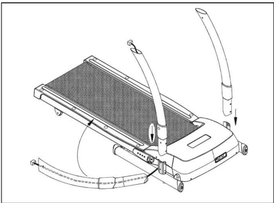
natural_image
Technical line drawing of a treadmill with attached lever and guide rails (no text or symbols)Fig.3
- Use an Allen wrench to loosely secure the two pedestals; do NOT tighten the screws firmly at this point.

text_image
curved washer flat washerFig.4
- Connect the upper data cable, insert the handle onto both the left and right pedestals. Please be carefully the data cable should be fully into the tubing, can't be pressed by pedestals.

natural_image
Technical line drawing of a treadmill with side and top views (no text or symbols)Fig.5
- Use the Allen wrench (M6) to loosely secure the upper fasteners on the pedestals. Do NOT tighten firmly.
text_image
curved washer flat washerFig.6
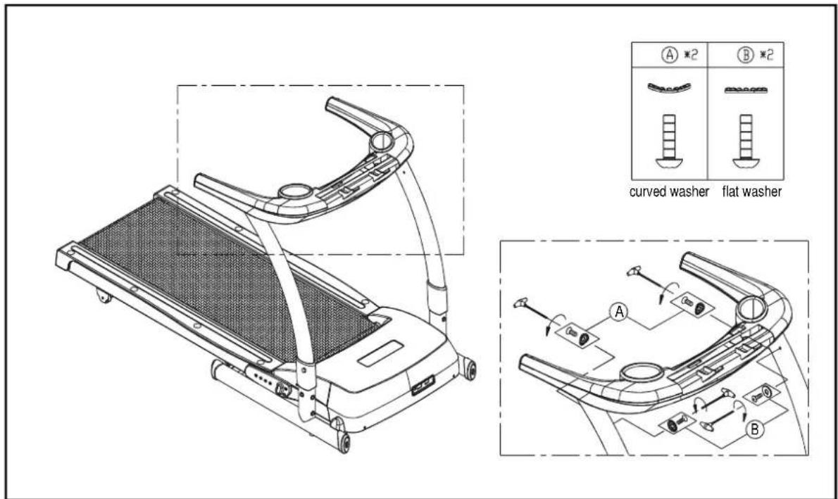
- Tighten the lower fasteners, then the upper fasteners. Finally push down each upright post cover until the screw cap fits onto the screw head.
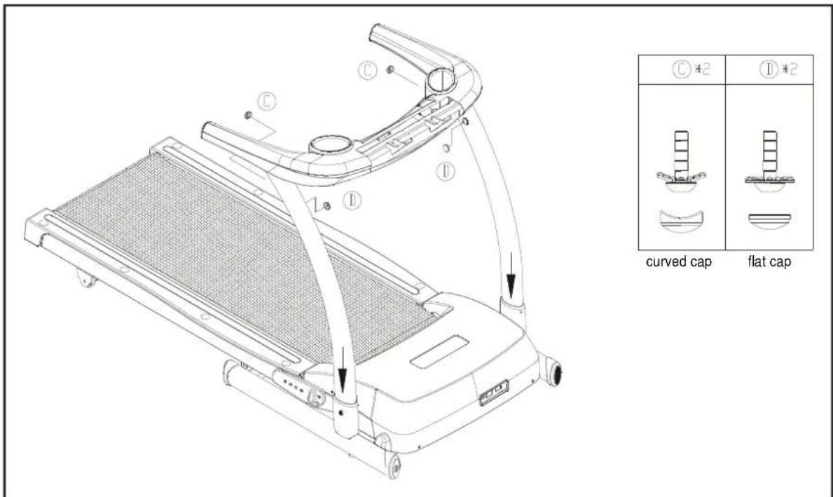
text_image
Technical diagram of a treadmill with labeled parts and corresponding CAD model views showing curved and flat cap configurations.Fig.7
- Please connect two data cables, as shown in figure A, before you assemble the display.

text_image
Technical diagram showing a treadmill control panel with labeled components and directional arrows indicating movement or assembly.Fig.8
- Carefully place the display onto the handle. Tighten the four screws to secure the display.

natural_image
Technical line drawing of a treadmill with control panel and side-view inset showing mechanical components (no text or symbols)Fig.9
CONNECT TO POWER
Connect the power cable as the figure shows, and secure it in place by tightening the screws.
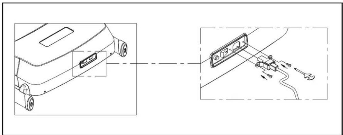
text_image
Technical diagram showing car door panel connection and cable assembly with labeled componentsFig.10
TR20F ELECTRONIC DISPLAY:
A. Electronics Display Layout:

flowchart
graph TD
    A["Incline Information"] --> B["INCLINE"]
    C["Dot Matrix Window"] --> D["SPEED"]
    E["Programs"] --> F["Scroll Button"]
    G["Workout Information Display"] --> H["Speed Information"]
    I["Programs"] --> J["Incline Information"]
    K["Speed Information"] --> L["Incline Information"]
    M["Programs"] --> N["Incline Information"]
    O["Programs"] --> P["Incline Information"]
    Q["Programs"] --> R["Incline Information"]
    S["Programs"] --> T["Incline Information"]
    U["Programs"] --> V["Incline Information"]
    W["Programs"] --> X["Incline Information"]
    Y["Programs"] --> Z["Incline Information"]
    AA["Programs"] --> AB["Incline Information"]
    AC["Programs"] --> AD["Incline Information"]
    AE["Programs"] --> AF["Incline Information"]
    AG["Programs"] --> AH["Incline Information"]
    AI["Programs"] --> AJ["Incline Information"]
    AK["Programs"] --> AL["Incline Information"]
    AM["Programs"] --> AN["Incline Information"]
    AO["Programs"] --> AP["Incline Information"]
    AQ["Programs"] --> AR["Incline Information"]
    AS["Programs"] --> AT["Incline Information"]
    AU["Programs"] --> AV["Incline Information"]
    AW["Programs"] --> AX["Incline Information"]
    AY["Hotels/Person"] --> AZ["HRC - 8% Carlo Heart Rate Zone CARDIO"]
    BA["HRC - 8% Carlo Heart Rate Zone CARDIO"] --> BB["HRC"]
    BC["HRC - 8% Carlo Heart Rate Zone NC/son"] --> BD["HRC - 8% Carlo Heart Rate Zone CARDIO"]
    BE["HRC - 8% Carlo Heart Rate Zone NC/son"] --> BF["HRC - 8% Carlo Heart Rate Zone CARDIO"]
    BG["HRC - 8% Carlo Heart Rate Zone NC/son"] --> BH["HRC - 8% Carlo Heart Rate Zone CARDIO"]
    BI["HRC - 8% Carlo Heart Rate Zone NC/son"] --> BJ["HRC - 8% Carlo Heart Rate Zone CARDIO"]
    BK["HRC - 8% Carlo Heart Rate Zone NC/son"] --> BL["HRC - 8% Carlo Heart Rate Zone CARDIO"]
    BM["HRC - 8% Carlo Heart Rate Zone NC/son"] --> BN["HRC - 8% Carlo Heart Rate Zone CARDIO"]
    BO["HRC - 8% Carlo Heart Rate Zone NC/son"] --> BP["HRC - 8% Carlo Heart Rate Zone CARDIO"]
    BZ["HRC - Select Program"] --> AA
    BW["Press Scroll ▼ to select program"] --> BX["Press OUTER"]
    BY["TIME DIST CALL SCAN"] --> BZ
    BZ --> AA
    BZ --> BX
    BZ --> BX
    BZ --> BX
    BZ --> BX
    BZ --> BX
Keypad Layout

flowchart
graph LR
    ENTER --> INCLINE
    INCLINE --> MODE
    MODE --> STOP
    STOP --> SPEED
    SPEED --> PressSpeed["Press Speed ▲ to Quick Start"]
B. Display Features:
Information W indow:
SPEED : 0.5 to 10 MPH / 0.8 to 16.0 KPH
INCLINE : 0 to 15%.
TIME : 00:00 to 99:59
DISTANCE : 0.00 to 99.99 Miles or 0.0 to 999.9 Km
CALORIES : 0.0 to 999.9 K-cal
HR : This readout gives you the heart rate detected during your workout. The range is from 40 to 250.
Range of Setting:
WEIGHT : 50\~275 lbs / 22\~125 kgs
PROGRAM : P1\~P5
CUSTOM INTERVAL : Rest, Work
CUSTOM COURSE : 8 Segments
HRC 65% : Fat Burn Heart Rate Zone
HRC 80% : Cardio Heart Rate Zone
Key Functions:
INCLINE:
Use the INCLINE ▲▼ keys to raise or to lower the treadmill. The incline range is from 0% to 15%.
SPEED:
The speed range is from 0.5 to 10 MPH or from 0.8 to 16.0 KPH. Use the SPEED ▲ keys to adjust your desired speed. If you are using the HTR feature, when the speed is over 4.0 MPH or 6.4 KPH, the message “FOR ACCURATE HR, HOLD SENSORS FIRMLY WHILE WALKING” will scroll through the display.
MODE:
- Press the MODE key to scroll through different modes of displays. With each press, the display will alternately show TIME → DIST → CAL → HR → SCAN → TIME.
Note: If your treadmill is not equipped with the heart rate feature, the display will not show the HR message in the MODE function.
-
DIST: Use the MODE key to select the DIST mode. When the DIST LED is lit in the display, use the MODE ▲▼ keys to adjust the desired distance. Each press of the key increases or decreases the distance by 0.1 mile or 0.1 km. If you hold the MODE▲▼ keys, distance will increase or decrease by 0.5 mile or 0.5 km.
-
TIME: Use the MODE key to select the TIME mode. When the TIME LED is lit in the display, use the MODE ▲▼ keys to adjust your desired time. Each press of the key increases or decreases the time by 1 minute. If you hold the MODE ▲▼ keys, time will increase or decrease by 5 minutes.
-
SCAN: The SCAN will alternate the display in the order of TIME → DIST → CAL → HR → TIME.
Note: There will be no HR readout if your treadmill is not equipped with the heart rate feature.
SCROLL:
Using this key, you can choose between PRO1 → PRO2 → PRO3 → PRO4 → PRO5 → Custom Interval → Custom Course → HRC 65% → HRC 80% → MANUAL. Press the Scroll key until your desired program appears in the window.
STOP/ PAUSE/ Hold to Reset:
-
In MANUAL mode, pressing this key will stop the treadmill. When the treadmill is stopped, hold this key for three seconds to reset the display, and all workout information will be erased.
-
In PROGRAM/ INTV mode, if you press this key during your workout in PRO1\~5, Custom Interval, or Custom Course, the treadmill comes to a gradual stop and the message window shows "PAUSE". All data remains and you can press the SPEED button to resume your workout. Pressing the STOP key for three seconds during your workout makes the display show the startup screen.
In the PAUSE mode, if you press the STOP key again, the display shows the startup screen.
- In HRC modes, pressing the STOP key during a workout stops HRC function; the display shows the startup screen.
SAFTY KEY:
The safety key must be in place for the treadmill to operate. This safety device is intended to stop the treadmill should a user stumble and fall. The display will show "PLACE SAFETY KEY" to remind the user to put the safety key in its proper place.
C. Programs:
MANUAL:
- Use the Scroll key to select the MANUAL mode.
- Press the SPEED ▲ key to activate the motor. If you did not input your desired TIME or DIST, related prompts will appear.
- You can set up your desired TIME or DIST as goals. When your goals are reached, the display beeps for three seconds. Afterwards, TIME or DIST starts to count up.
- INPUT YOUR PERSONAL INFORMATION:
When the motor and the incline functions are not activated, hold the MODE key for three seconds. You can then follow prompts to input your personal information. "INPUT YOUR WEIGHT" will scroll through the window. The preset weight will appear; press MODE ▲▼ keys to change your weight setting. Press MODE again to exit this setting. Your information will be memorized and the display will revert to MANUAL mode. The input weight range is from 50 to 275 lbs or from 22 to 125 kgs.
PROGRAMS 1 \~5
- Use the SCROLL key to choose PRO 1 \~PRO 5; the corresponding LED will blink.
- Choose one program you like and press ENTER to confirm your selection. The message "PRESS MODE ▲▼ TO SELECT TIME OR DIST" will appear. Press MODE ▲▼ to set up your desired TIME or DIST. Once you begin your workout, TIME or DIST will count down.
2.1 If you choose TIME, a preset value of 10:00 will appear and the TIME LED will light. The INCLINE window will show the current incline rate. The SPEED information window will show 0.0. Press MODE ▲▼ to adjust the time. The maximum time is 60 minutes. Press SPEED ▲to begin your workout.
2.2 If you choose DIST, a preset value of 1:00 will appear and the DIST LED will light. The INCLINE information window will show the current incline rate. The SPEED information window will show 0.0. Press MODE ▲▼ to adjust the distance. The maximum distance is 10 miles or kilometers. Press SPEED▲to begin your workout.
Note: if you press the STOP key before speeding up, the display will show the startup screen.
-
Press the SPEED▲key to start the treadmill. Press TIME or DIST to count down based on the values input. When TIME or DIST values reach zero, the treadmill enters COOL DOWN mode.
-
If you press the STOP key during your workout, the treadmill comes to a gradual stop and all workout data remains. If you press SPEED ▲ again, the walk belt rotates from the lowest speed to the previous speed setting. You can further adjust the speed by pressing SPEED ▲▼ keys.
-
When the treadmill is in PAUSE mode, the display reverts to the startup setting if you press the STOP key.
-
Preset values of PRO 1\~5:
PRO 1 :
Speed (MPH) : 0.5, 1.8, 1.8, 3.1, 3.1, 1.8, 1.8, 0.5
Speed (KPH) : 0.8, 3.0, 3.0, 5.1, 5.1, 3.0, 3.0, 0.8
Incline : 0%, 3%, 3%, 6%, 6%, 3%, 3%, 0%
PRO 2 :
Speed (MPH) : 0.5, 4.6, 3.1, 0.5, 4.6, 6.1, 4.6, 0.5
Speed (KPH) : 0.8, 7.6, 5.1, 0.8, 7.6, 10.1, 7.6, 0.8
Incline : 0%, 0%, 3%, 3%, 0%, 0%, 3%, 3%
PRO 3 :
Speed (MPH) : 0.5, 1.8, 3.1, 4.6, 0.5, 1.8, 3.1, 4.6
Speed (KPH) : 0.8, 3.0, 5.1, 7.6, 0.8, 3.0, 5.1, 7.6
Incline : 0%, 0%, 3%, 3%, 6%, 6%, 3%, 3%
PRO 4 :
Speed (MPH) : 0.5, 1.8, 4.6, 3.1, 0.5, 1.8, 4.6, 4.6
Speed (KPH) : 0.8, 3.0, 7.6, 5.1, 0.8, 3.0, 7.6, 5.1
Incline : 0%, 3%, 0%, 3%, 0%, 3%, 0%, 3%
PRO 5:
Speed (MPH) : 0.5, 3.1, 0.5, 3.1, 0.5, 3.1, 0.5, 3.1
Speed (KPH) : 0.8, 5.1, 0.8, 5.1, 0.8, 5.1, 0.8, 5.1
Incline : 0%, 0%, 3%, 3%, 6%, 6%, 8%, 8%
CUSTOM INTERVAL (INTV 1):
-
Once you choose the Custom Interval mode, the corresponding LED will be lit and the screen will show "INTV1". Press ENTER to confirm your choice. The message "ENTER REST SPEED & INCLINE & TIME" will scroll across the screen. REST appears in the information window. TIME, SPEED, and INCLINE information windows will show values from the last workout session. Press MODE ▲▼ keys to set the REST time; press SPEED ▲▼ keys to set the REST speed; press INCLINE ▲▼ keys to set the REST incline. Press ENTER to confirm all input values.
-
After you input your rest period goals, a message "ENTER WORK SPEED & INCLINE & TIME" will scroll across the message window. WORK appears in the information window. TIME, SPEED, and INCLINE information windows will show values from the last workout session. Press MODE ▲▼ keys to set the WORK time; press SPEED ▲▼ keys to set the WORK speed; press INCLINE ▲▼ keys to set the WORK incline. Press ENTER to confirm all input values.
- During your workout, you can still change your SPEED and INCLINE anytime by pressing ▲▼ keys. When you leave this mode, all your input values remain in memory.
- The TIME setting range is from 60 to 250 seconds. Each press of MODE ▲▼ keys changes the time setting by 10 seconds. If you hold these keys, time will increase or decrease by 10 seconds. If you do not press any adjustment keys within six seconds, the message "PRESS ENTER" will scroll across the window.
CUSTOM COURSE (INTV 2):
- Once you choose the Custom Course mode, the corresponding LED will light and the screen will show "INTV2". Press ENTER to confirm your choice. The message "ENTER SEGMENT 1 SPEED & INCLINE & TIME" will scroll across the window. SEG1 will appear in the information window.
- Press MODE ▲▼ keys to set the SEG1 time; press SPEED ▲▼ keys to set the SEG1 speed; press INCLINE ▲▼ keys to set the SEG1 incline. Press ENTER to confirm all input values.
- After you input the desired SPEED, INCLINE, and TIME for all eight segments, the treadmill is ready to operate. If you do not press any adjustment keys within six seconds, the message “PRESS ENTER” will scroll across the window.
- In either segment, if you input zero as TIME or SPEED values, that segment is then considered the last segment to be completed.
HRC-65% / HRC 85%:
Note 1: These two modes are only available on those treadmills with the HRC function.
Note 2: It is recommended to use a heart rate transmitter belt. The receiver board is already built into the display.
- Press the "Scroll" key until HRC 65% (FAT) or HRC85% (CARDIO) LED lights up. Press the ENTER key to confirm your choice. The window shows "FAT" or "CARDIO".
-
When you press the "ENTER" key, "INPUT YOUR AGE" will scroll across the dot matrix window. A preset value, "AGE 35," appears.
-
Use ▲ or ▼ key to input your age; relative target heart rates will be shown accordingly.
- Press ENTER to confirm your age input. The message "MODIFY YOUR HEART RATE LIMIT" will scroll across the display and "MDFY" will appear in the window. Use ▲ / ▼ keys to modify your target heart rate, and press ENTER to confirm your choice.
- TIME will appear in the message window and a preset value of 05:00 will appear on the dot matrix window. Press ▲▼ keys to set your desired workout time for this mode. Press ENTER to confirm your input.
- Press SPEED▲▼ keys to set the maximum speed. The message window will show "MAX" and the motor will start running. If no heart rate signal is detected at this time, you will not be able to start the treadmill. Before entering the HRC program, TIME counts up. In the HRC program, TIME counts down and the treadmill makes adjustments to keep your heart rate near the target heart rate.
GUIDELINES FOR EXERCISE
How hard should I exercise?
Studies show that to achieve the benefits of aerobic exercise, it is necessary to work within your training zone. Your training zone depends on your age and level of fitness.
The above chart indicates the recommended Heart Rate training zones (darkened area of the chart). These figuress are calculated by taking 220 minus your age, and calculating 80% for your maximum and 65% for the minimum heart rate for aerobic exercise.
CAUTION:

line
| YOUR AGE | YOUR HEART RATE | | --------- | --------------- | | 20 | 200 | | 25 | 195 | | 30 | 190 | | 35 | 185 | | 40 | 180 | | 45 | 175 | | 50 | 170 | | 55 | 165 | | 60 | 160 | | 65 | 155 | | 70 | 150 | | 75 | 145 | | 20 | 160 | | 25 | 156 | | 30 | 152 | | 35 | 148 | | 40 | 144 | | 45 | 140 | | 50 | 136 | | 55 | 132 | | 60 | 128 | | 65 | 124 | | 70 | 120 | | 75 | 116 | | 20 | 130 | | 25 | 127 | | 30 | 124 | | 35 | 120 | | 40 | 117 | | 45 | 114 | | 50 | 111 | | 55 | 107 | | 60 | 104 | | 65 | 101 | | 70 | 97 | | 75 | 94 |Heart Rate training zones are approximations. Always check with your physicians to learn what appropriate heart rate level is best for your fitness level.
How long should I exercise?
The duration of your exercise session depends on your fitness level. In general, it is recommended that you maintain your heart rate in the training zone for at least 15 to 20 minutes to realize an aerobic benefit. Beginners should always start slowly and bring their workout sessions up to 20 minutes or more. As your fitness level increases, you will be able to maintain your heart rate in the training zone for longer periods: Usually between 20 and 30 minutes.
When first starting your workout, use the first several minutes to warm up, then slowly increase your workload to bring your heart rate into your specific training zone. At the end of your workout, gradually decease your workload, then exercise lightly as a "cool down".
How often should I exercise?
Research indicates to achieve the greatest benefits, should be performed 3-5 times a week. It is important to allow sufficient time, at least 24 hours, for your body to recover after exercise.
ADJUST THE RUNNING BELT
The belt is properly aligned at the factory. However, the belt may move off the center during shipping and handling or by use on an uneven surface. Therefore, it is important that you check the belt's alignment before using the treadmill.
The correct alignment of the running belt is critical for the smooth operation of the treadmill.
CAUTION: Do not allow any one to walk on the running belt during this procedure.
The gap between the edge of the running belt and the edge of the landing strip should be equal on both sides of the treadmill. If gap A and B are not even, adjust the walk belt immediately.
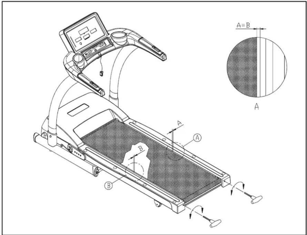
text_image
Technical line drawing of a treadmill with labeled components and a cross-sectional view showing A and B measurement areas.Fig.11
Failure to adjust the walk belt could result in damage which is not covered by the warranty. Please follow the belt adjustment procedure as follows.
BELT ADJUSTMENT PROCEDURE
- Turn on the power switch located at the front of the treadmill. Place the safety key in its position.
- Press the SPEED ▲ button to increase the speed to 2.0mph/3.2kph. Determine belt placement in relation to landing strips on both sides of the treadmill. Make sure the edge of the walk belt is aligned and parallel to the edge of the landing strip. Also make sure the width of area A and B is approximately the same. Observe walk belt operation for about 30 seconds.
- Adjust the walk belt immediately if it is not parallel to the edge of the landing strip and the width of area A and B are not the same. Please follow the steps below to return the belt to the proper area.
- If the belt is too far left: Turn the left belt adjustment bolt located at the rear of the treadmill clockwise 1/4 turn at a time, using the Allen wrench. Then turn the right belt adjustment bolt counterclockwise 1/4 turn. Let the treadmill run 30 seconds, then check the position of the belt. If the belt still has not returned to the proper zone, repeat with another 1/4 turn on both sides until the belt has returned to the proper zone. Do not turn the adjusting bolt more than 1/4 turn at a time.
- Conversely, if the belt is too far right, turn the right belt adjustment bolt clockwise 1/4 turn, then turn the left adjustment bolt counterclockwise 1/4 turn. Then let the treadmill run at least 30 seconds; check the position of the belt. If it still has not returned to the proper zone, repeat with another 1/4 turn until the belt has returned to the proper zone. Do not turn adjusting bolt more than 1/4 turn at a time.
Periodically monitor the position of the belt to ensure peak performance:
When you are using the treadmill, if you feel a pause in the belt with each foot plant, the belt may be too loose. Stop the machine to check the belt tension, pull the running belt up in the middle (see Fig.12-1 & 12-2). There should be about 30 ~m / m (1 1/8") or 3kgs of "give" in the belt (see Fig.12-3). If there is too much, adjust both rear roller bolts clockwise 1/4 turn at a time (see Fig.12-1). Then, check the belt tension again, if more adjusting is required, give both adjusting bolts another slight turn. Do not adjust over 2 full turns.

natural_image
Line drawing of a treadmill with labeled center and motion arrows (no text or symbols on the device itself)
text_image
About 30m/m (1-1/8inch) 3Kg(6.6 Pound) Belt Running deck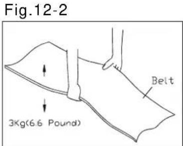
text_image
Fig.12-2 3Kg(6.6 Pound) BeltFig.12-3
Conversely, if there is not enough "give", adjust both rear roller bolts counterclockwise 1/2 turn at a time.
CAUTION: To avoid injury, special care must be taken when adjusting the running belt. Remove any loose clothing or shoelaces and tie back your hair. Be very careful to keep your fingers or any other objects clear of the belt and rollers.
The treadmill is designed to carry specific weights at specific speeds. The treadmill will not stop immediately if an object becomes caught in the belt or rollers.
Over tightening of the belt causes damage and premature failure of the precision bearings in the front and rear rollers.
FOLDING AND UNFOLDING THE TREADMILL
Make sure the treadmill has come to a complete stop and the incline display shows "0" before folding.
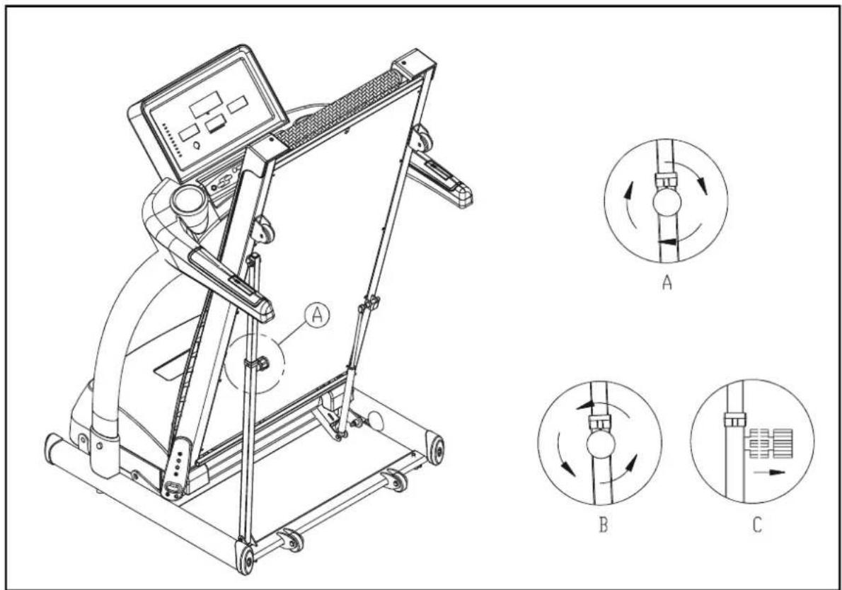
text_image
Technical line drawing of a treadmill with labeled components and three circular diagrams (A, B, C) illustrating mechanical or electrical system rotation.Fig.13
- Tilt up the walk deck. Tighten the knob by turning it clockwise as shown in figure A.
Note: The locking feature is essential to the safety of people and pets. Lock the treadmill to avoid operation when the treadmill is folded.
- Unfold the treadmill by turning the knob counterclockwise and pull out the knob to release it as shown in figures B & C. Put down the treadmill very slowly until the treadmill is steady on the floor.
FLOOR LEVEL ADJUSTMENT
Fold the treadmill as shown. Turn the floor levelers a1, a2, b1, b2 so that all four adjustments are even and the treadmill stands level on the floor.
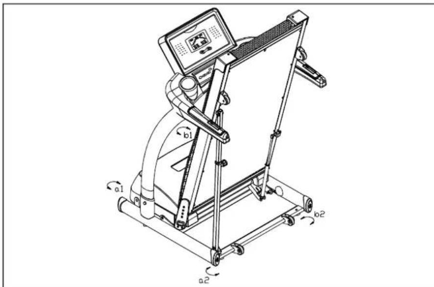
text_image
Technical line drawing of a treadmill with labeled motion directions (a1, b1, a2) and control panelFig.14
Unfold the treadmill completely. Apply some pressure to sides A and B as shown in the diagram below. If transport wheel A does not touch the ground, adjust levelers a1 and a2 by turning them in the same direction and with the same number of turns so that they will touch the floor evenly.
Similarly, when applying pressure to sides A and B, if transport wheel B does not touch the ground, adjust levelers b1 and b2 by turning them in the same direction and with the same number of turns so that they will touch the floor evenly. Adjust the levelers until the treadmill is steady and firmly placed on the ground. Finally, turn the leveler adjustment nut to secure it against the treadmill frame (refer to picture C).
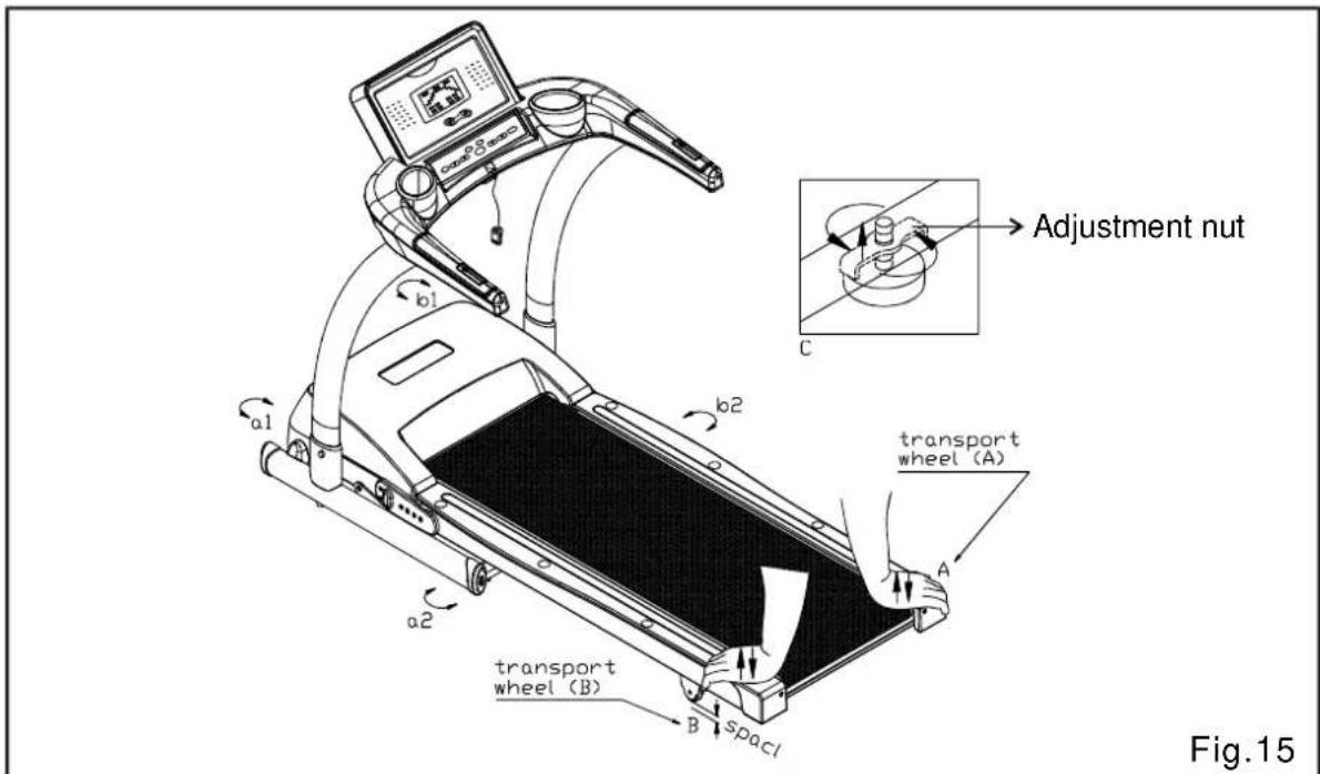
text_image
Adjustment nut C a1 b1 b2 transport wheel (A) a2 transport wheel (B) B SpacI Fig.15TROUBLE SHOOTING:
CAUTION: ALWAYS SHUT OFF THE UNIT AND DISCONNECT THE AC CORD BEFORE MAKING ANY REPAIRS OR MODIFICATIONS.
Error Messages
If the electronic display shows "E-1, E-3, E-7, E-10 or E-14", please turn off the power switch.
Allow the unit to rest for five seconds and turn on the power switch again. If the display shows "ERR" again, please contact your dealer for further instructions.
E-1: No signal is coming from the optical switch mounted on the motor.
E-3: Treadmill speed doesn't match the setting. Contact your local dealer for assistance.
E-7: The display is not receiving a correct VR signal. The VR may be malfunctioning, or wires might not be connected properly. Make sure the data cable is connected securely, or contact your dealer for further information. (This detection only takes place when the power switch is turned on.)
E-14: The motor temperature is too high. Please switch off the treadmill and allow the treadmill to rest for one hour to cool down the motor. Then resume normal use again.
How to relieve the ERR 7 restriction?
When the "E-7" message appears, the DC motor will not operate. Try the following method to start the treadmill: Remove the safety key after powering up the treadmill. Hold both INCLINE ▲▼ keys for three seconds. The display will show “SPEED on” then show the same startup screen that appears when the safety key is not in place. Place the safety key back in place. The treadmill will operate again.
MAIN FUSE FAILURE
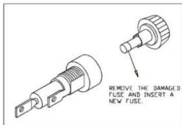
If the display remains dark after turning on the treadmill, the fuse may be damaged and need to be replaced.
CAUTION: MAKE SURE THE TREADMILL POWER PLUG IS REMOVED FROM THE POWER OUTLET BEFORE REPLACING THE FUSE.
The main power fuse is located near the on/off switch (see Fig.16). 12amp/100-120 volts or 7amp/220-240 volts. To remove the main fuse, push the fuse cap toward the machine and turn it counterclockwise, then pull out the fuse cap. Remove the fuse from the cap. Insert a new fuse of the appropriate type into the fuse cap and insert it into the machine. Turn the fuse cap clockwise to secure the fuse in place. (See Fig. A, B, C.)

natural_image
Technical line drawing of a mechanical component with a cylindrical pin and housing, no text or symbols presentFig.16

text_image
Technical diagram showing a mechanical component with labeled parts including 'PUSH', 'TURN', and numbered callouts ① and ②.A
text_image
REMOVE THE DAMAGED FUSE AND INSERT A NEW FUSE.B
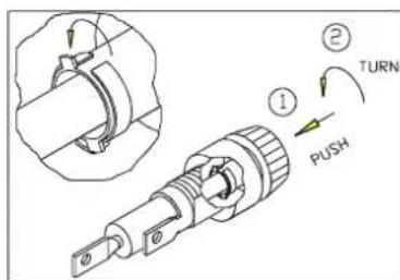
text_image
Technical diagram showing a mechanical assembly with labeled parts and directional arrows, including 'PUSH' and 'TURN' annotations.C
If the unit does not work after changing the fuse, please contact your authorized SportArt Fitness service technician for more information.
Wiring Schematic:
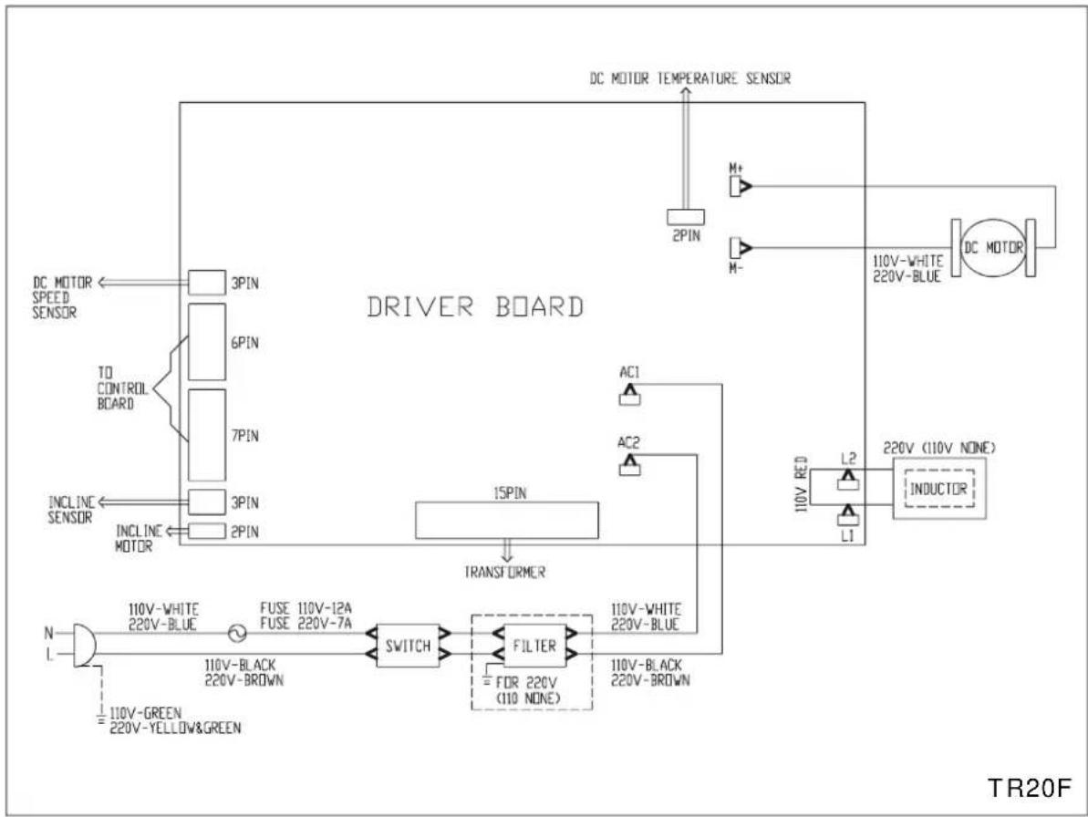
flowchart
graph TD
    A["DC MOTOR SPEED SENSOR"] --> B["3PIN"]
    B --> C["6PIN"]
    C --> D["7PIN"]
    D --> E["3PIN"]
    E --> F["INCLINE SENSOR"]
    F --> G["INCLINE MOTOR"]
    H["AC1"] --> I["15PIN"]
    I --> J["TRANSFORMER"]
    K["AC2"] --> I
    L["110V-WHITE 220V-BLUE"] --> M["DC MOTOR"]
    N["110V-RED L2"] --> O["220V (110V NONE)"]
    P["110V-BLACK 220V-BROWN"] --> Q["110V-BLACK 220V-BROWN"]
    R["FUSE 110V-12A FUSE 220V-7A"] --> S["110V-Black 220V-BROWN"]
    T["SWITCH"] --> U["FILTER"]
    U --> V["FOR 220V (110 NONE)"]
    W["TR20F"] --> X["INDUCTOR"]
    Y["DC MOTOR TEMPERATURE SENSOR"] --> Z["2PIN"]
    AA["M+"] --> AB["M-"]
    AC["M-"] --> AD["110V-WHITE 220V-BLUE"]
Your Authorized Distributor