6300 - Tapis de course SportsArt - Notice d'utilisation et mode d'emploi gratuit
Retrouvez gratuitement la notice de l'appareil 6300 SportsArt au format PDF.

Questions des utilisateurs sur 6300 SportsArt
0 question sur cet appareil. Repondez a celles que vous connaissez ou posez la votre.
Poser une nouvelle question sur cet appareil
Téléchargez la notice de votre Tapis de course au format PDF gratuitement ! Retrouvez votre notice 6300 - SportsArt et reprennez votre appareil électronique en main. Sur cette page sont publiés tous les documents nécessaires à l'utilisation de votre appareil 6300 de la marque SportsArt.
MODE D'EMPLOI 6300 SportsArt
TABLEOFCONTENTS
-
INTRODUCTION.... 1
-
ASSEMBLING YOUR TREADMILL.... 4
List of parts.... 4
-
TREADMILL ASSBMELY.... 5
-
HOW TO USE YOUR 6300 TREADMILL....12
CSAFE Operation Guide.... 15
- GUILDLINES FOR EXERCISE.... 18
How hard should I exercise? 18
How long should I exercise? 18
How often should I exercise?...... 18
-
ADJUSTING THE RUNNING BELT.... 19
-
FLOOR LEVEL ADJUSTMENT.... 21
-
TOTAL ACCUMULATED TIME AND DISTANCE.... 22
-
TROUBLE SHOOTING.... 23
Service Required....23
Error Messages....23
Fuse failure for incline system....23
Main fuse failure....24
- Wiring Schematic.... 25
SPORTSART 6300 COMMERCIAL TREADMILL
INTRODUCTION
Congratulations on purchasing one of the finest piece of commercial exercise equipment on the market today, the SportsArt 6300 Commercial Treadmill. The 6300 is designed with the end user in mind and constructed of high quality materials and designed for years of trouble-free use.
Before using your SportsArt 6300 Treadmill, we recommend that you familiarize yourself with this Owner's Manual. Whether you are a first time user of a treadmill or a seasoned "PRO", understanding the correct use of the equipment will enhance your ability to achieve your exercise goals safely and successfully.
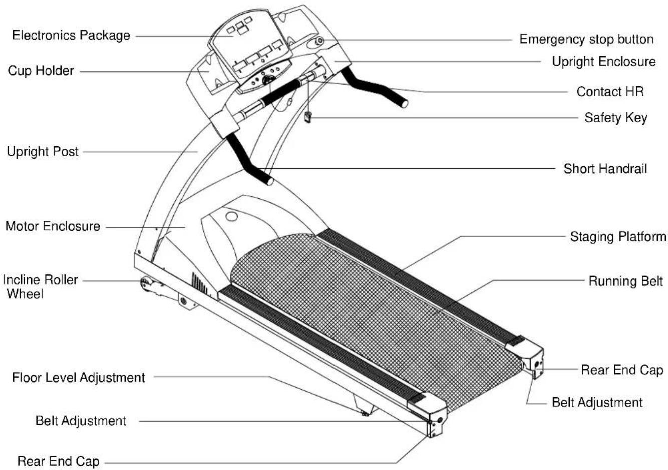
text_image
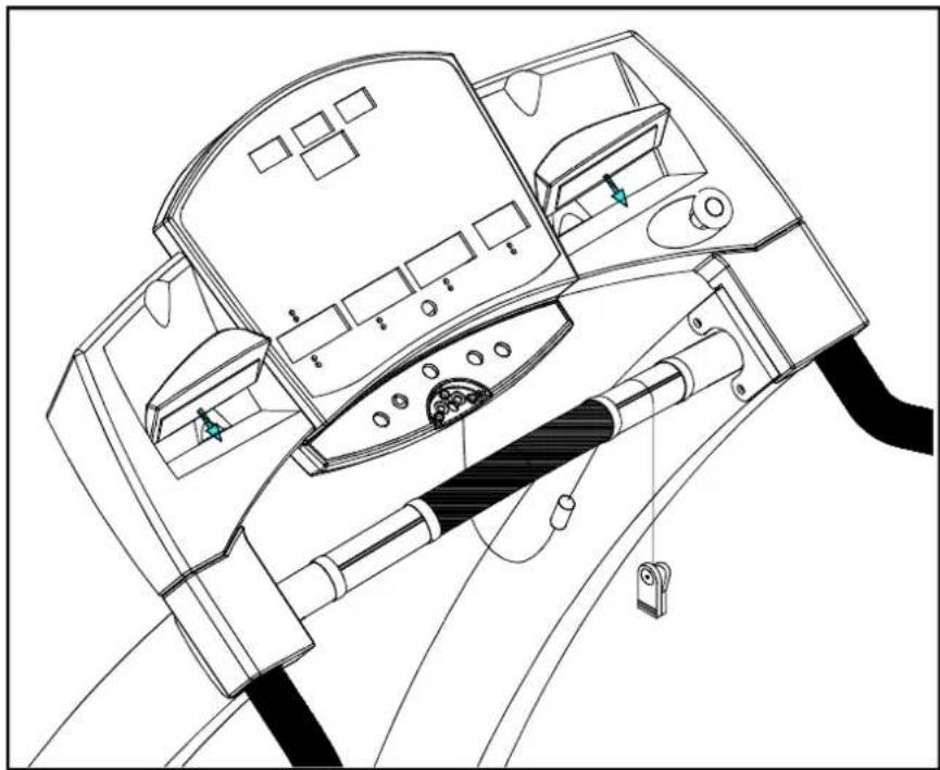
Electronics Package Cup Holder Upright Post Motor Enclosure Incline Roller Wheel Floor Level Adjustment Belt Adjustment Rear End Cap Emergency stop button Upright Enclosure Contact HR Safety Key Short Handrail Staging Platform Running Belt Rear End Cap Belt AdjustmentYour SportsArt treadmill was designed and built for optimum safety. However, certain precautions apply when ever you use your treadmill.
Please read the entire manual before assembly and operation. Also, please note the following safety precautions:
SAFETY Precautions:
- Read this owner's manual and follow the instructions
- Assemble and operate the treadmill on a solid, level surface. Do not use outdoors or near water.
- Never allow children on or near the treadmill.
- Check the treadmill before every use. Make sure all parts are assembled, and all fastneers are tightened. DO NOT use the treadmill if the unit is disassembled in any way.
- Keep your hands away from moving parts.
- Wear proper workout clothing: DO NOT wear loose clothing. DO NOT wear shoes with leather soles or high heels. Tie all long hair back.
- Use care when mounting and dismounting the unit.
- DO NOT use any accessories that aren't specifically recommended by the manufacturer. These might cause injuries or cause the unit to fail.
- Unplug from outlet before servicing or removal of any parts.
- Close supervision is necessary when this treadmill is used by, on, or near children, invalids, or disabled persons.
- Use this treadmill only for its intended use as described in this manual.
- Never operate this treadmill if it has been damaged in any way. If it is not working properly, been dropped or damaged, contact your dealer.
- Do not carry this treadmill by power cord or use cord as a handle.
- Keep the power cord away from heated surfaces.
- Keep all air ventilation areas free of blockage.
- Never drop or insert any object into any opening.
-
Do not operate where aerosol (spray) products are being used or where oxygen is being administered.
-
Connect this treadmill to a properly grounded outlet only.
• ETL/GS approved 150kgs user weight.
CAUTION:
If you feel any pain or abnormal symptoms, STOP YOUR WORKOUT and consult your physician immediately. Work within your recommended exercise level. DO NOT work to exhaustion.
Before beginning any exercise program, you should consult with your doctor. It is recommended that you undergo a complete physical examination.
Do not stand on the belt when starting. Straddle the belt with your feet on the right and left staging platforms.
Always use the safety cord when operating the treadmill.
DANGER:
Improper connection of the equipment-grounding connector can result in a risk of electric shock. Check with a qualified electrical or service person if you are in doubt as to whether the treadmill is properly grounded. Do not modify the plug provided with 6300 treadmill, if it doesn't fit the outlet, get the proper outlet installed by a qualified technician.
ASSEMBLINGYOURTREADMILL
Installation Requirements
Thank you for purchasing our product. Even though we go to great efforts to ensure the quality of each product, occasional errors and/or omissions do occur. In any event should you find the product to be defective or missing a part please contact yourdealer.
Please read this owner's manual and follow the instructions.
Caution: Two persons are recommended to assemble the treadmill. To avoid back strain, and to ensure safety to the unit and yourself, we suggest you avoid lifting the running bed assembly from box. Instead drop the sides of the box and slide the treadmill from the container rather than lifting it.
IMPORTANT: The packing for this treadmill was designed to protect it during shipment, please store the original packing in a safe place in case you need to ship the unit in the future.
Listof Parts
Before assembling your treadmill, make sure that you have all following items:
- 8pcs 5/16" x L1" bolts
- 8pcs 5/16 ' washers
- 6pcs 1/4" x L1/2" handlebar bolts (For display area)
- 2pcs M4*L12 upright post enclosure screws.
- 8pcs 5/16" x L15 philip screws (for display)
- One screw driver
- 3pcs hex allen wrench (4mm. 5mm. 6mm)
- One hex allen wrench with handle. (6mm)
- Left & right upright post enclosures. 2pcs
- Fuse-15A(100V/120V) or 10A(200V/240V)
- One wrench for emergency release button. (For maintenance purpose)
- 4pcs 5/16" x 1" screws (for optional long handrail or medical handrail)
- 4pcs 1/4" x 3/4" screws (for optional medical handrail)
- 4pcs 1/4" washers (for optional medical handrail)
- 8pcs upright post screw caps (for philip screws)
- 8pcs upright post screw caps (for 5/16" x L1" bolts)
TREADMILL A SSEMBLY
Instructions
When you remove the treadmill from its box, first check to make sure all of the parts are present. Then, read through the assembly instructions before you begin.
- Tip the treadmill on its side. Make sure the running belt is in position in the tracks of the Belt Alignment Guides on the underside of the machine. (See Fig.1). Be sure to remove and disclose of shipping blocks located along the side of the bed and removed from the underside.
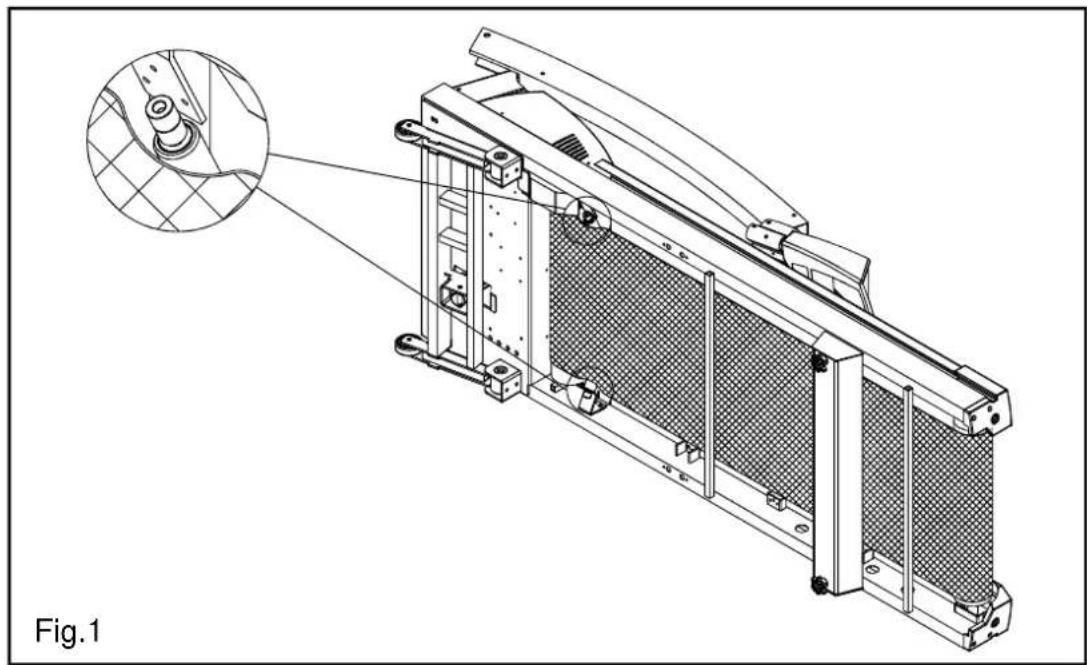
natural_image
Technical line drawing of a mechanical component with a magnified inset showing internal structure (no text or symbols)- (1) Rotate upright posts into their respective position, securing each side with the screws provided.
(2) According to Pic. A, press the screw caps to their respective position.

text_image
Fig.2- Rotate display to fixed position as figure below, attach all side fasteners to position without fully tightened. (See Fig. 3)

natural_image
Technical line drawing of a treadmill with motion indicators and a close-up inset showing the blade rotation (no text or symbols)- Insert short handrail into Handlebar Bracket, then secure 6 screws provided and fully tighten all side fasteners. (See Fig.4)
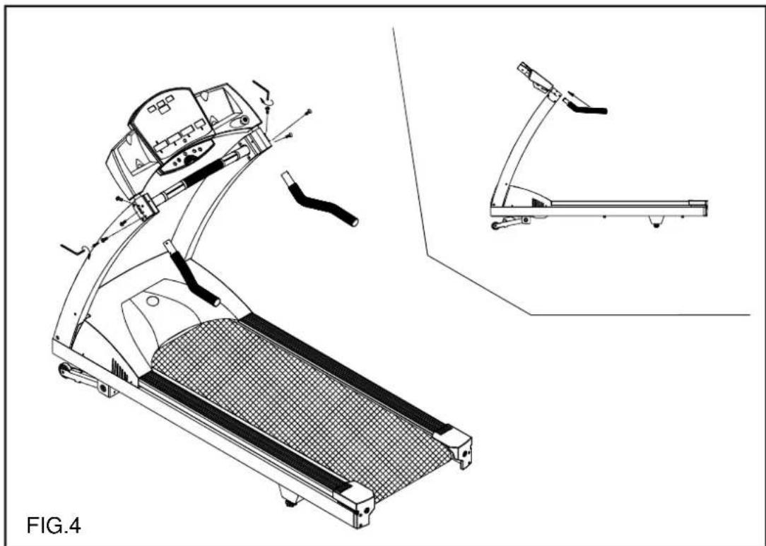
natural_image
Technical line drawing of a treadmill with attached armrest and side view (no text or symbols)- Place upright post's enclosure into respective position, then secure screws from behind. (See Fig. 5)

text_image
Press down FIG.5- Insert upright post screws caps into proper position. (See Fig.6)
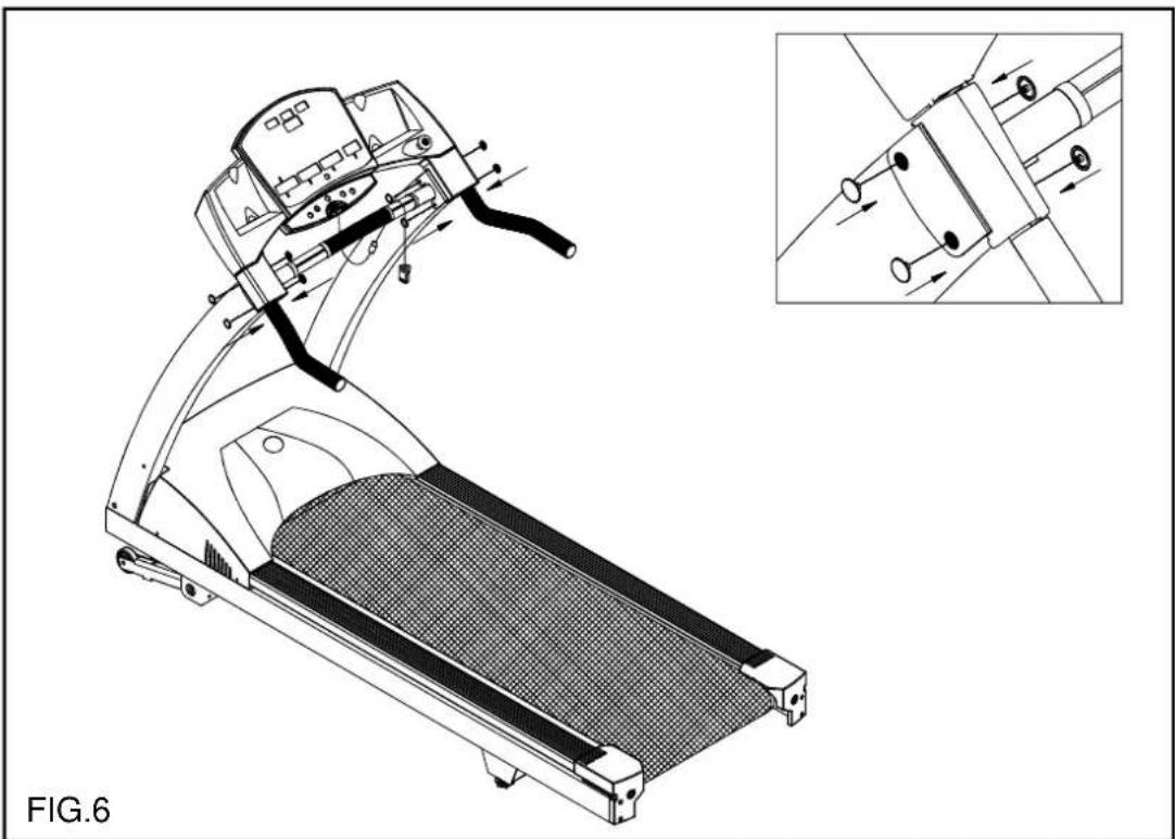
natural_image
Technical line drawing of a treadmill with internal components and a close-up inset showing mechanical assembly (no text or symbols)- Connect power cable as indicated in Fig.7, and fasten it.

natural_image
Technical line drawing of a mechanical assembly with a component and motion arrows, labeled FIG.7 (no text or symbols on the diagram itself)For long handrail assembly:
- Insert Long handrail into Handlebar Bracket then secure the fasteners provided and fully tighten all side fasteners. (See Fig.4-1)

natural_image
Technical line drawing of a treadmill with attached components and a close-up inset showing the same body (no text or symbols present)- Press upright post's enclosure into respective position. (See Fig.5-1)

natural_image
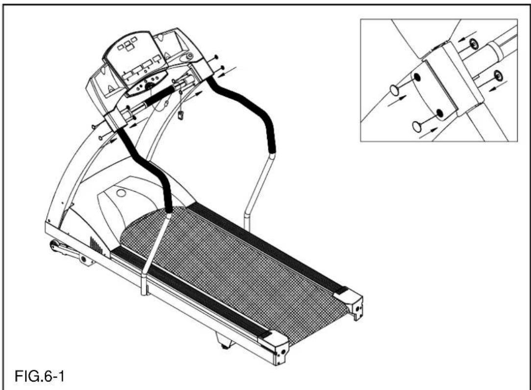
Line drawing of a treadmill with attached control panel and handle, labeled FIG.5-1 (no text or symbols on the diagram itself)- Insert upright post screw caps into proper position. (See Fig.6-1)
natural_image
Technical line drawing of a treadmill with internal components and a close-up inset showing mechanical assembly (no text or symbols)- Connect power cable as indicated in Fig.7-1, and fasten it.

natural_image
Technical line drawing of a mechanical assembly with a component and motion arrows, labeled FIG.7-1 (no text or symbols on the diagram itself)For medical handrail assembly: (New Type)
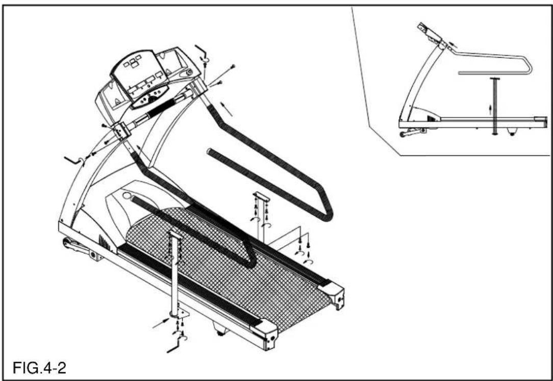
- Insert medical handrail into the upper handrail bracket. Attach screws to position without fully tightening. Install medical handrail post and tighten all screws. (See Fig.4-2)
natural_image
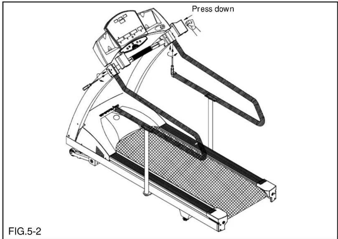
Technical line drawing of a treadmill with motion control arrows and a close-up inset showing the same device (no text or symbols present)- Press upright post's enclosure into respective position, and attach the screws from the backside. (See Fig.5-2)
text_image
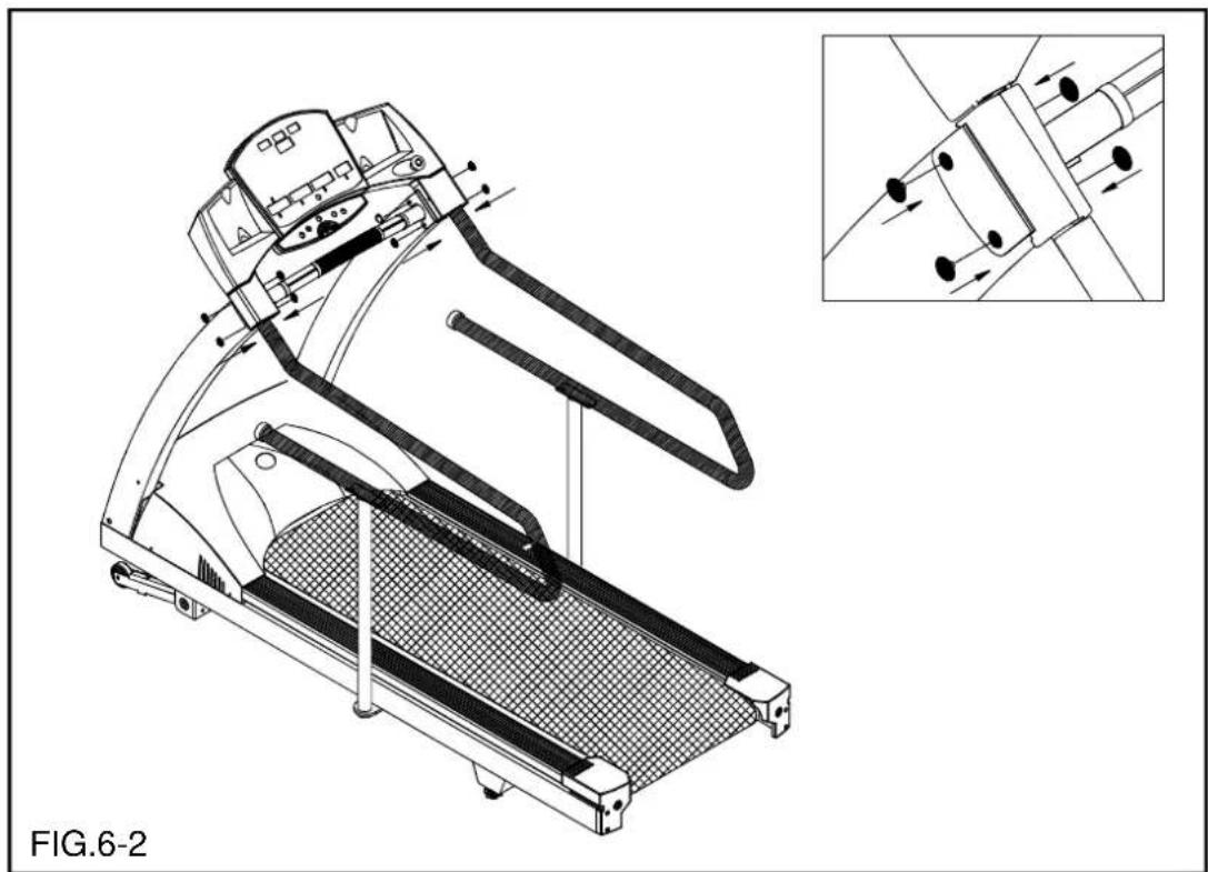
Press down FIG.5-2- Insert upright post screw caps into proper position. (See Fig.6-2)
natural_image
Technical line drawing of a treadmill with internal components and an inset showing mechanical assembly (no text or symbols)HOW TO USE YOUR 6300 TREADMILL:
1. Button functions
SPEED: 1. Press ▲▼ to increase and decrease the belt speed.
- The speed range is from 0.1mph to 12mph; 0.2kph to 20kph.
- At any time you can push SPEED up button for QUICK START.
INCLINE: 1. Press ▲▼ to increase and decrease the incline.
- The incline range is from 0-15%.
- Use INCLINE button to enter AGE and WEIGHT.
STOP: 1. Press the STOP button to stop the tread belt. All data will remain.
- Press and hold the STOP button to reset all data.
- During program use, push the STOP button will pause progress of the course and pressing SPEED up button will resume the program.
ENTER: The button is for entering data (AGE, WEIGHT, etc).
CHANGE: CHANGE will toggle the feedback between the upper and lower rows of information DISTANCE, CALORIES, TIME, SPEED and INCLINE, CAL/HR, PACE, METS.
SCROLL: This button will scroll through the preprogrammed courses for selection. The corresponding LED will indicate the course.
2. Basic operation:
A. To start using the treadmill:
I. Press any key.
II. Enter AGE (AGE LED will light up), press INCLINE up, down button to select age and then press ENTER.
III. Enter WEIGHT (WEIGHT LED will light up), press INCLINE up, down button to set WEIGHT, and then press ENTER.
IV. Select TIME (TIME LED will light up, and the minute numeric will flash), press INCLINE up, down button to set TIME and then press ENTER.
- The pre-set time is 30 minutes.
- When the time is set at "0", the manual mode will be counting up and all the other programmed courses will be counting down. The pre-set time will be 30 minutes.
- When the time is not set at "0", (the minimum time will be 10 minutes, and the maximum time will be 99 minutes) then the manual mode and other programmed courses will be counting down.
V. SPEED display will show 0.0 and flash, press the SPEED up button to shart Treadmill and press INCLINE to select a desired incline.
3. Quick start:
At any time, for Quick Start press the SPEED up button to start the treadmill. The treadmill will start at 0.1mph/0.2kph.
4. Display functions:
A. DISTANCE: Displays total miles or kilometers.
B. CALORIES: Total accumulated calories burned.
C. TIME: Displays total time accumulated or time remaining in a preprogrammed course.
D. SPEED: Press these keys to adjust your desired speed. The speed range for the treadmill is from 0.1-12mph (0.2-20kph).
E. INCLINE: Press these keys to raise or lower the treadmill. The incline range for the treadmill is from 0 to 15%.
F. CAL/HR: Calories consumed per hour at the current rate of exercise.
G. PACE: Displays minute per mile or kilometer.
H. METS: (Metabolic Equivalents): One MET is equivalents to an oxygen consumption of 3.5 ml/kg/min. 1MET = 3.5 ml/kg/min.
I. STOP (RESET): Press STOP button, treadmill will stop running, time and distance will remain. Holding STOP for 3 second will reset the display.
J. ENTER: Value entering confirmed button.
K. EMERGENCY STOP BUTTON: This button allows the user an additional safety feature in case of emergency. Upon pushing the button the treadmill will stop, and there is a long line across four windows and the small LED of Reset Emergency STOP Button will flashing too. To reset the button rotate the button clockwise and the treadmill will reset for proper use.
L. CHANGE: Press this button to alternate between 2 groups of information - DISTANCE, CALORIES, TIME and SPEED, and INCLINE, CAL/HR, PACE and METS.
M. PULSE: If the treadmill is equipped a Polar Receiver for Heart Rate monitoring without transmitter. You need to purchase a transmitter / HR strap to measure your heart rate during your workout.
5. Personal Cardio Advisor:
When you enter your age, Personal Cardio Advisor automatically calculates your suggested low, mid and high Heart Rate range, 65%, 72.5%, 80%, of max heart rate. It is highly recommended that you always check with your physician to learn what the appropriate heart rate level is for your fitness level.
6. Emergency Stop Button:
This feature is a secondary safety feature that allows the user, in an emergency situation, to stop the treadmill. When the button has been pushed, rotate the button clockwise to release. The treadmill will not operate if the button is depressed.
7.Course Description
Press the scroll button to select a preprogrammed courses.
- Manual: Manual is the default program for QUICK START. Press SPEED up to begin.
II. TIME can be set under all programmed courses (minimum 10 minutes to maximum 99 minutes). Refer to P.12 for the time setting instructions. At the end of the course, the display will prompt you that the treadmill will be going to COOL DOWN. The speed will then change to 2.5mph and be in manual course.
III. Bay Run

IV. River Run

V. Climber's Trek

During the workout of preprogrammed course, every adjustment to the incline level will directly result in the change to the preset figures. (eg. increase the incline level by 1%, will result in a overall change to the preset level by 1%, vice versa)
8. CSAFE Operation Guide
When you connect 6300 Treadmills to external instruments, such as computers and medical equipment, the words "ENTER ID PRESS ENTER KEY" scroll across the dot matrix screen. This message prompts you to press the ENTER key and to input a user ID. The treadmill will then enter "idle mode".
- After you press ENTER, the display will show "00000". Press "Incline ▲▼" to select numbers from 0 to 9, then press the "Change" key to determine decimal placement. Once a user ID is selected, press the ENTER key to confirm your choice. The connecting instrument will then be able to identify whether the user ID is true or false. The words "SUBMITTING ID" will scroll across the display.
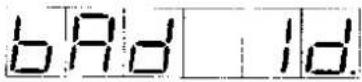
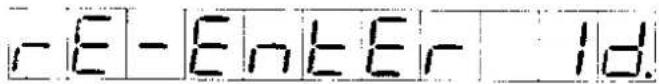
A. If a false ID is input, the words "BAD ID RE-ENTER ID" will scroll across the display. Input a valid ID to proceed to the next step.
B. If the ID is valid, the words "ID ACCEPTED" will scroll across the display. Other user information, including age, weight, and workout time, can then be entered, and the workout can begin. During and after the workout, the connected device can read workout data and user information.
Note: If the SCROLL or SPEED▲ key is pressed before the user presses the ENTER key to input user ID, the treadmill will enter manual mode. In manual mode, the user can activate the treadmill, but the connected device cannot read workout data and user information. After the workout in manual mode is finished, the words "ENTER ID PRESS ENTER" will scroll across the display.
- If any key other than ENTER is pressed, the treadmill enters manual mode.
- If the user ID is not input within about one minute, the word "UNAVAILABLE" scrolls across the display, indicating that communication between the treadmill and the connected device has been terminated. The treadmill display will show the startup banner. The treadmill must be reconnected to the device to establish CSAFE control.
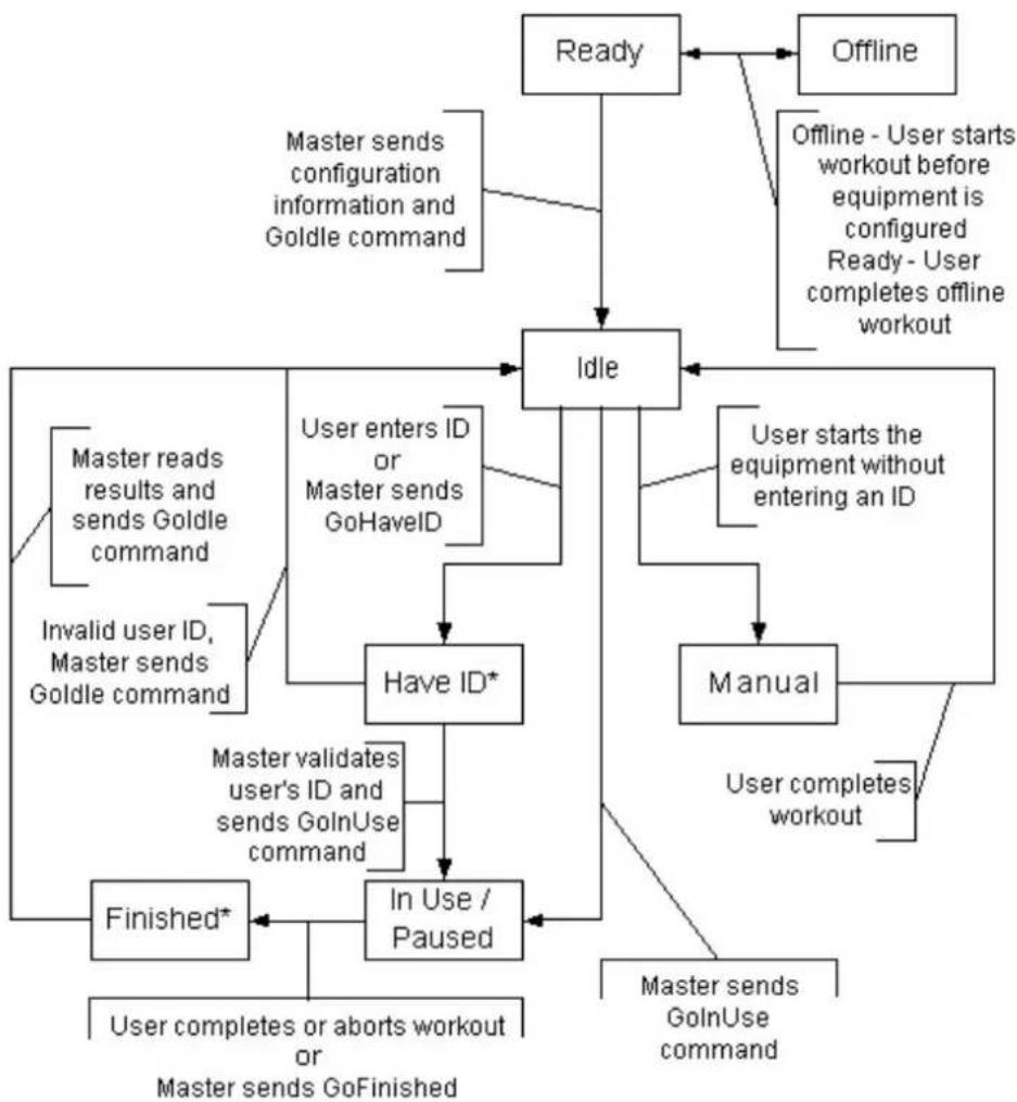
Note: User IDs should be established and maintained by the manager of the connecting instrument. All users should obtain permission of the device manager before receiving IDs from the manager. The following flow chart explains the CSAFE control process. In this chart, the term "Master" refers to the connected device, and the term "Slave" refers to the treadmill.
flowchart
graph TD
    A["Ready"] --> B["Idle"]
    C["Offline"] --> B
    B --> D["Have ID*"]
    D --> E["In Use / Paused"]
    E --> F["Finished*"]
    F --> G["Finished*"]
    H["User starts the equipment without entering an ID"] --> D
    I["User completes workout"] --> E
    J["User completes aborts workout or GoFinished"] --> F
    K["Master sends configuration information and Goldle command"] --> B
    L["Master reads results and sends Goldle command"] --> D
    M["Invalid user ID, Master sends Goldle command"] --> D
    N["Master validates user's ID and sends GoInUse command"] --> E
    O["User completes offline workout"] --> B
    P["User enters ID or Master sends GoHaveID"] --> D
    Q["Master sends GoInUse command"] --> E
* Equipment should implement a timeout condition if no response from the Master is received within appropriate period of time.
Text contrast Table
ENTER ID PRESS ENTER KEY

text_image
Enter Id Pr ESS EnterSUBMITTING ID

BAD ID RE-ENTER ID
text_image
- E - E n t E r - 1 d.ID ACCEPTED

UNAVAILABLE

text_image
UnARILABLEENTER ID PRESS ENTER KEY

text_image
Enter 1d Print 55 EnterGUIDELINES FOR EXERCISE
How hard should I exercise?
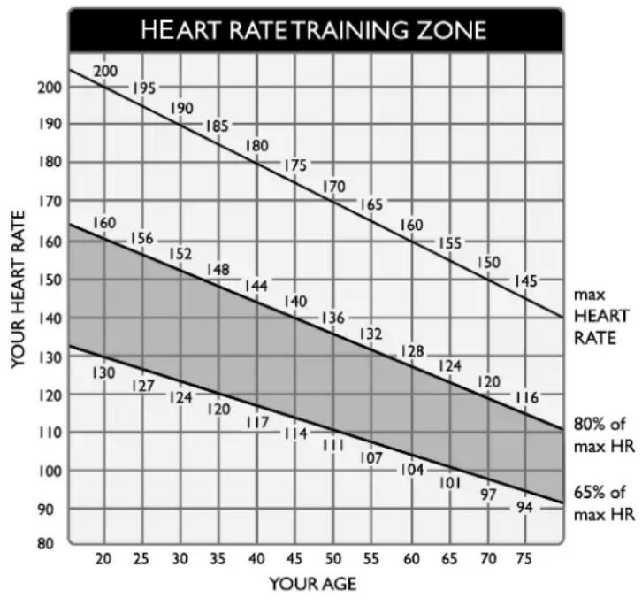
Studies show that to achieve the benefits of aerobic exercise, it is necessary to work within your training zone. Your training zone depends on your age and level of fitness.
The above chart indicates the recommended Heart Rate training zones (darkened area of the chart). These figuress are calculated by taking 220 minus your age, and calculating 80% for your maximum and 65% for the minimum heart rate for aerobic exercise.
line
| YOUR AGE | YOUR HEART RATE | | --------- | --------------- | | 20 | 200 | | 25 | 195 | | 30 | 190 | | 35 | 185 | | 40 | 180 | | 45 | 175 | | 50 | 170 | | 55 | 165 | | 60 | 160 | | 65 | 155 | | 70 | 150 | | 75 | 145 | | 20 | 160 | | 25 | 156 | | 30 | 152 | | 35 | 148 | | 40 | 144 | | 45 | 140 | | 50 | 136 | | 55 | 132 | | 60 | 128 | | 65 | 124 | | 70 | 120 | | 75 | 116 | | 20 | 130 | | 25 | 127 | | 30 | 124 | | 35 | 120 | | 40 | 117 | | 45 | 114 | | 50 | 111 | | 55 | 107 | | 60 | 104 | | 65 | 101 | | 70 | 97 | | 75 | 94 |CAUTION:
Heart Rate training zones are approximations. Always check with your physicians to learn what appropriate heart rate level is best for your fitness level.
How long should I exercise?
The duration of your exercise session depends on your fitness level. In general, it is recommended that you maintain your heart rate in the training zone for at least 15 to 20 minutes to realize an aerobic benefit. Beginners should always start slowly and bring their workout sessions up to 20 minutes or more. As your fitness level increases, you will be able to maintain your heart rate in the training zone for longer periods: Usually between 20 and 30 minutes.
When first starting your workout, use the first several minutes to warm up, then slowly increase your workload to bring your heart rate into your specific training zone. At the end of your workout, gradually decease your workload, then exercise lightly as a "cool down".
How often should I exercise?
Research indicates to achieve the greatest benefits, should be performed 3-5 times a week. It is important to allow sufficient time, at least 24 hours, for your body to recover after exercise.
ADJUSTING T HERUNNINGBELT
The 6300 treadmill includes a belt alignment gauge located on the left side of the motor enclosure. The edge of the running belt should be in the middle of the green portion of the gauge. If the belt edge is in the green area, the belt is properly adjusted. If the edge of the belt is in the red portion, the belt needs adjusting immediately (see Fig.6)
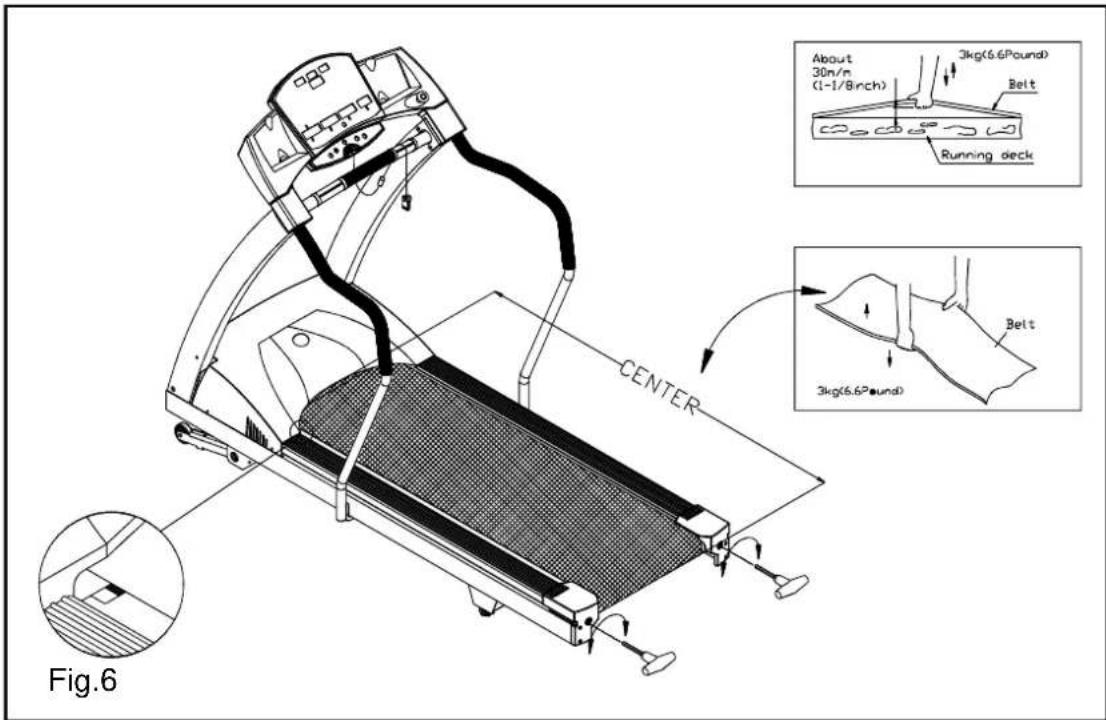
text_image
About 30n/m (1-1/8inch) 3kg(6.6Pound) Belt Running deck CENTER 3kg(6.6Pound) Belt Fig.6The belt is properly aligned at the factory. However, during shipping and handling or by use on an uneven surface, the belt may move off center. Therefore, it is important that you check the belt's alignment before using the treadmill. The correct alignment of the running belt is critical for the smooth operation of the treadmill.
CAUTION: DO NOT ALLOW ANYONE TO WALK ON RUNNING BELT DURING THIS PROCEDURE.
Failure to realign the belt could result in tearing or fraying of the belt, which is not covered in the warranty.
Please follow the belt adjustment procedure listed below:
- Turn on the power switch located on the front of treadmill.
- Press the SPEED ▲ button to increase the speed until the speed reaches 2.0 mph/3.2kph on the display.
- While the unit is running at 2 mph/3.2kph, determine where the belt is in relation to the belt alignment gauge.
-
Should the belt be in the red color range, follow the steps below to return the belt to the proper operating position.
-
If the belt is in the left red zone: Using the hex Allen wrench, turn the left belt adjustment bolt, located at the rear of the treadmill, clockwise 1/4 turn at a time, Then turn the right belt adjustment bolt counter-clockwise 1/4 turn. Let the treadmill run 30 seconds. Always checking the position of the belt in the color gauge. If the belt still has not returned to the green safety zone, repeat with another 1/4 turn until the belt has returned to the middle of the green area. Do not turn adjusting bolt more than 1/4 turn at a time.
If the belt is on the edge of the green color, please adjust it so it is in the middle of the green color. You may turn the adjustment nut less than 1/4 turn at a time.
- Conversely, if the belt is in the right red zone, turn the right belt adjustment nut clockwise 1/4 turn, then turn the left adjustment bolt counterclockwise 1/4 turn. Let the treadmill run at least 30 seconds, while checking the position of the belt in the color gauge. If it stills has not returned to the green safety zone, repeat with another 1/4 turn until the belt has returned to the middle of the green area. Do not turn adjusting bolt more than 1/4 turn at a time.
- When the belt is back in the green "safety zone", you can continue your regular use of the treadmill. Slowly increase the speed of the unit to 5.5 MPH (9 KPH), and let it run for at least 45 seconds.
- When you are using the treadmill, if you feel a pause in the belt with each foot plant the belt is too loose. Stop the machine, adjust both rear roller bolts clockwise 1/2 turn at a time. Try the machine again, then check the result, if more adjusting is required, give both adjusting bolts another slight turn. Do not adjust over 2 fullturns.
- If the belt is too tight, this will adversely effect the life of the unit.
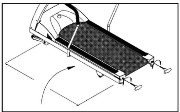
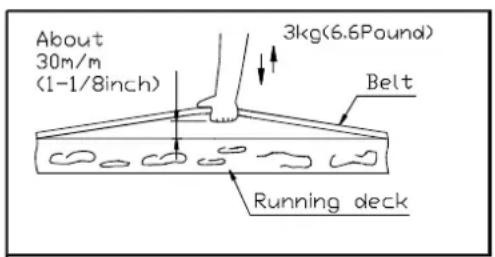
- To check the correct tension of the belt, grab the belt in the middle, and lift up about 30m/m (1 1/8") or 3 kg (6.6 pounds) of force (see Fig.7,7-1,7-2).
natural_image
Mechanical assembly diagram showing a slide-like device with rotating components and directional arrows (no text or symbols)Fig.7-3
text_image
About 30m/m (1-1/8inch) 3kg(6.6Pound) Belt Running deckFig.7-1

text_image
3kg(6.6Pound) BeltFig.7-2
- If the belt is too loose, you can tighten the belt by equally adjusting both rear roller bolts clockwise 1/2 turn at a time. Conversely, if the belt is too tight, adjust both rear roller bolts counterclockwise 1/2 turn at a time (see Fig.7-3).
Periodically monitor the position of the belt to ensure peak performance
CAUTION: To avoid injury, special care must be taken when adjusting the running belt. Remove any loose clothing or shoes lace and tie back your hair. Be very careful to keep your fingers or any other objects clear of the belt and rollers.
The treadmill is designed to carry specific weights. The treadmill will not stop immediately if any object becomes caught in the belt or rollers.
Over tightening of the belt causes damage and premature failure of the precision bearings in the front and rear rollers.
FLOOR LEVEL ADJUSTMENT
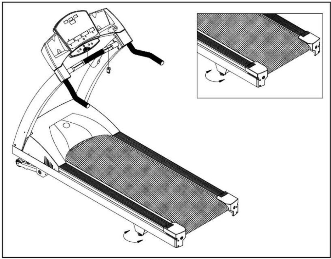
If the treadmill is unsteady on your floor, turn the floor level adjustment on the rear feet of the treadmill. Raise or lower the floor level adjustment to steady your treadmill (see Fig.8)
natural_image
Technical line drawing of a treadmill with an inset showing the blade assembly (no text or symbols)Fig.8
Adjust the floor level adjustment to make the treadmill steady.
PS: Rear floor level adjustment should be adjusted and tightened properly. Or some noise might be caused while working out.
Tear the Twin Adhesives on the Cup Holders open; affix Cup Holders onto two sides of the Electronic Display Board. Press tightly as shown in this drawing. (see Fig.9)
natural_image
Technical line drawing of a mechanical device with control panel and lever mechanism (no text or symbols)Fig.9
TOTAL ACCUMULATED TIME AND DISTANCE
The 6300 display electronics allow the club owner or technician to monitor distance and time.
(1) Show the total distance.
(2) Show the total time.
Press and hold the CHANGE button for three seconds during the banner.
-
Total Distance will be displayed, ACCU????? press ENTER to advance to total time.
-
Display Total Time ????:00 ????? Accumulate Total Time (unit: hour)
-
Press any button to exit accumulative data mode, display will return to default banner.
TROUBLESHOOTING
Service Required
When Service Required LED lights up, please stop using this treadmill and contact your dealer for more information.
Errormessages
- E-1: The optical switch mounted on the motor is not receiving the signal reflected from the tachometer wheel. Please contact your dealer.
- E-3: Treadmill speed doesn't match the setting. Contact your local dealer for assistance.
- E-7: The electronics are receiving the signal reflected from the VR (Potentiometer) incorrectly, which means the terminal wires are either disconnected or the VR is damaged. Please contact your dealer for more information.
- E-6: Inspect and replace the incline system fuse.
Fuse Failure For Incline System
Should the incline system not operate, and displays "E-6" on the display, please replace the incline system fuse.
The 4 amp fuse is for the Incline system. To remove the incline system fuse, push on the fuse holder then turn the holder counterclockwise and the fuse holder with fuse will protrude. Remove the damaged fuse and insert a new one, push the fuse and holder in, then turn clockwise to secure the fuse holder (see Fig.9\~Fig.9-3).
If the incline system still does not function after changing the fuse, please contact your dealer for more information.
Main Fuse Failure
If nothing is displayed on the electronics display, please check the POWER switch located on the front of the treadmill. If it is ON, then the fuse may be damaged and must be replaced.
CAUTION: MAKE SURE THE TREADMILL POWER PLUG IS REMOVED FROM OUTLET BEFORE REPLACING THE FUSE.
There is one fuse holder located at the front, inside of the treadmill frame, (15 amp/100-120volts or 10 amp/220-240volts). This is for the Main Power (see Fig.10). Please make sure to check your standard voltage prior to selecting correct fuse for replacement.
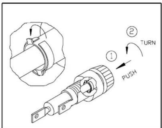
To remove the Main fuse, push the fuse holder in and turn the holder counterclockwise and remove the fuse holder with fuse. Replace the damaged fuse and insert a new one, reinstall the holder, then turn clockwise to secure. (See Fig.10 to Fig.10-3).

text_image
FUSE(100V-120V=15A) 200V-240V=10A)Fig.10

text_image
Technical diagram showing a mechanical assembly with labeled parts including 'PUSH', 'TURN', and numbered callouts ① and ②.Fig.10-1

text_image
REMOVE THE DAMAGED FUSE AND INSERT A NEW FUSE.Fig.10-2
text_image
① ② TURN PUSHFig.10-3
If the unit does not work after changing the fuse, please contact your dealer for more information.
To further disable the treadmill from use, you can remove the fuse to make the unit in-operable.
Wiring Schematic:

flowchart
graph TD
    A["DC MOTOR SPEED SENSOR"] --> B["5PIN"]
    A --> C["8PIN"]
    A --> D["10PIN"]
    A --> E["2PIN"]
    A --> F["3PIN"]
    G["CONNECTOR TO CONTROL BOARD"] --> H["POWER of INCLINE MOTOR"]
    G --> I["VR of INCLINE MOTOR"]
    J["Temperature Switch of DC MOTOR"] --> K["2PIN"]
    L["FUSE 110V-15A\nFUSE 220V-1GA"] --> M["AC1"]
    N["FUSE 220V-BROWN 110V-BLACK"] --> O["SWITCH"]
    P["FUSE 220V-BROWN 110V-GREEN"] --> Q["220V-BROWN 110V-BLACK"]
    R["AC2 FILTER"] --> S["L(BLACK)"]
    R --> T["N(WHITE)"]
    U["TRANSFORMER"] --> V["15PIN"]
    W["WHITE"] --> X["AC2"]
    Y["AC1"] --> Z["L1"]
    AA["L2"] --> AB["M+"]
    AC["Inductor"] --> AD["M-"]
    AE["DC MOTOR"] --> AF["110V-BLACK 220V-BROWN"]
    AG["110V-WHITE 220V-BLUE"] --> AH["DC MOTOR"]
    AI["220V-RED 110V-BLACK"] --> AJ["Inductor"]
Your Authorized Distributor