6005 - Tapis de course SportsArt - Notice d'utilisation et mode d'emploi gratuit
Retrouvez gratuitement la notice de l'appareil 6005 SportsArt au format PDF.

Questions des utilisateurs sur 6005 SportsArt
0 question sur cet appareil. Repondez a celles que vous connaissez ou posez la votre.
Poser une nouvelle question sur cet appareil
Téléchargez la notice de votre Tapis de course au format PDF gratuitement ! Retrouvez votre notice 6005 - SportsArt et reprennez votre appareil électronique en main. Sur cette page sont publiés tous les documents nécessaires à l'utilisation de votre appareil 6005 de la marque SportsArt.
MODE D'EMPLOI 6005 SportsArt
TABLE OF CONTENTS
- INTRODUCTION.... 2
- ASSEMBLING YOUR TREADMILL
Step by step instruction.... 3
Floor level adjustment.... 5
- MODES OF OPERATION
Manual.... 6
Set.... 6
- WORKOUT OPTIONS
Interval 1....7
Interval 2....8
Pre-programmed courses.... 9
Race.... 10
-
RUNNING ON THE TREADMILL.... 12
-
MAINTAINING TREADMILL.... 12
Cleaning the treadmill.... 13
Adjusting the running belt.... 13
- TROUBLE SHOOTING
ERR message.... 16
Fuse failure for electronics package and motor.... 16
Fuse failure for incline system.... 17
Fuse Failure For driver board.... 18
SAFETY GUIDELINES:
Please read and follow the following safety guidelines:
- Read this owner's manual and follow the instructions.
- Assemble and operate the treadmill on a solid, level surface.
- Never allow children on or near the treadmill.
- Check the treadmill before every use. Make sure all parts are assembled, and all nuts and bolts are tightened. Do not use the treadmill if the unit is disassembled in any way.
- Keep your hands away from moving parts.
- Wear proper workout clothing: do NOT wear loose clothing. Do not wear shoes with leather soles or high heels. Tie all long hair back.
- Don't rock the unit from side to side, and use care when mounting and dismounting the unit.
- Do not use any accessories that aren't specifically recommended by the manufacturer - - these might cause injuries or cause the unit to fail.
- Work within your recommended exercise level -- do NOT work to exhaustion.
- If you feel any pain or abnormal symptom, STOP YOUR WORKOUT and consult your physician immediately.
- The weight limit for this treadmill is 400 LBS (180 KGS).
- Before beginning any exercise program, you should consult with your doctor. It is recommended that you undergo a complete physical examination.
INTRODUCTION:
Congratulations on purchasing one of the finest pieces of exercise equipment on the market today. Constructed of high quality materials and designed for years of trouble-free usage, the 6005 treadmill will be an integral part of your fitness regimen.
Before using your treadmill, we recommend that you familiarize yourself with this Owner's Manual. Whether you are a first time user of an exercise equipment or a seasoned "pro", understanding the correct use of the equipment will enhance your ability to achieve your exercise goals safely and successfully.
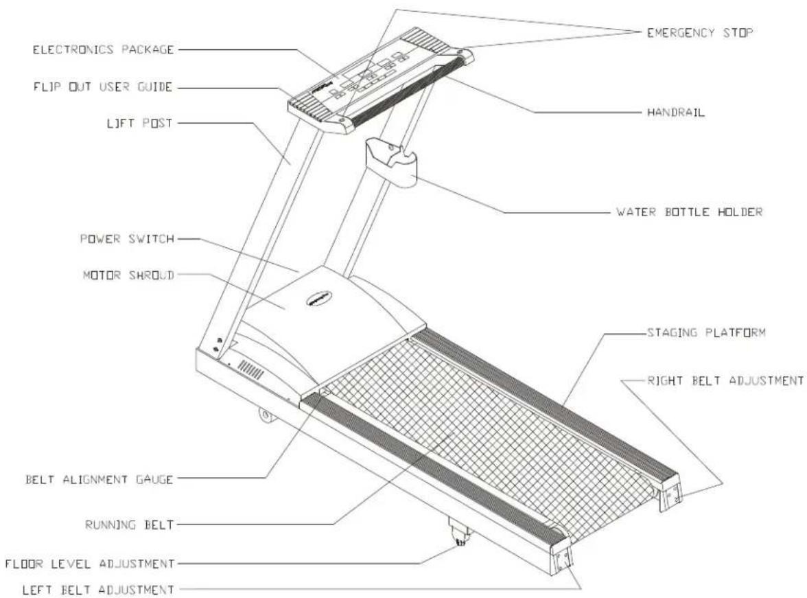
text_image
ELECTRONICS PACKAGE FLIP OUT USER GUIDE LIFT POST POWER SWITCH MOTOR SHROUD BELT ALIGNMENT GAUGE RUNNING BELT FLOOR LEVEL ADJUSTMENT LEFT BELT ADJUSTMENT EMERGENCY STOP HANDRAIL WATER BOTTLE HOLDER STAGING PLATFORM RIGHT BELT ADJUSTMENTASSEMBLING YOUR TREADMILL:
Installation Requirements
Read this owner's manual and follow the instructions contained herein.
Caution: Two persons are recommended to assemble the treadmill. To avoid back strain, and to ensure safety to unit and yourself, we suggest you avoid lifting the running bed assembly from box. Instead, lay the treadmill down drop sidewalls of box and slide treadmill from the container rather than lifting it.
IMPORTANT: The packing for this treadmill was designed to protect it during shipment, please store the original packaging in a safe place in case you need to ship the unit in the future.
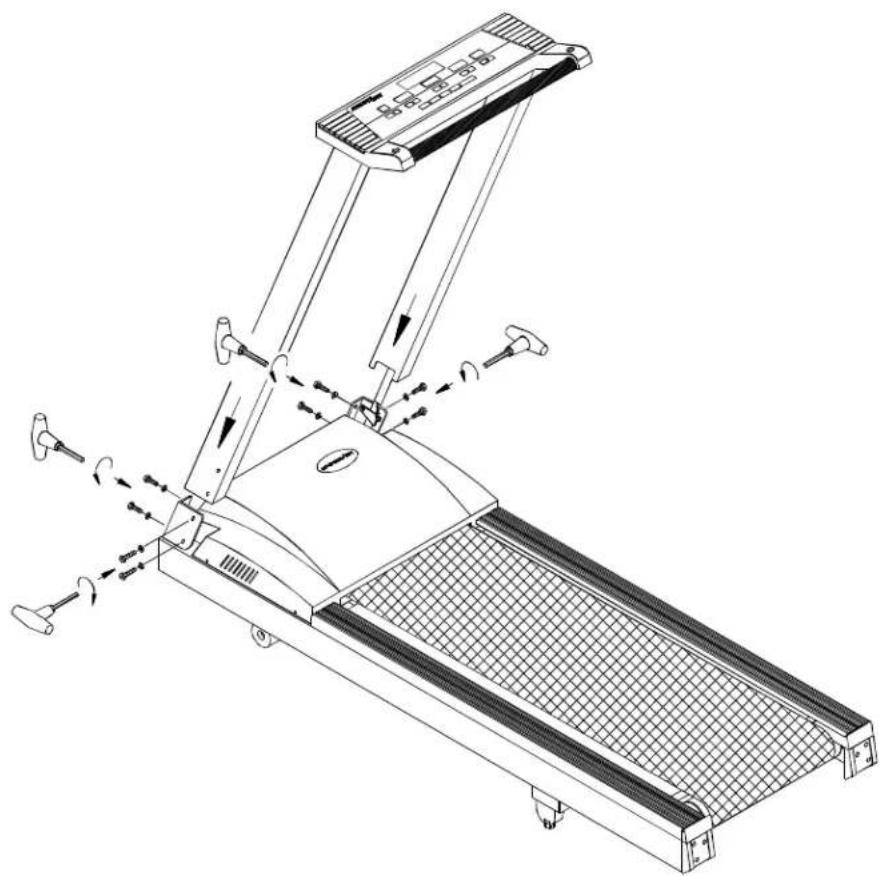
Step by step instructions:
When you remove the treadmill from its box, first check to make sure all of the parts are present. Then, read through the assembly instructions before you begin.
- Slide posts into the treadmill frame. Then secure with four bolts and washers on each side (see Fig.1)
natural_image
Line drawing of a treadmill with adjustable arms and wheels, showing motion indicators (no text or symbols)Fig.1
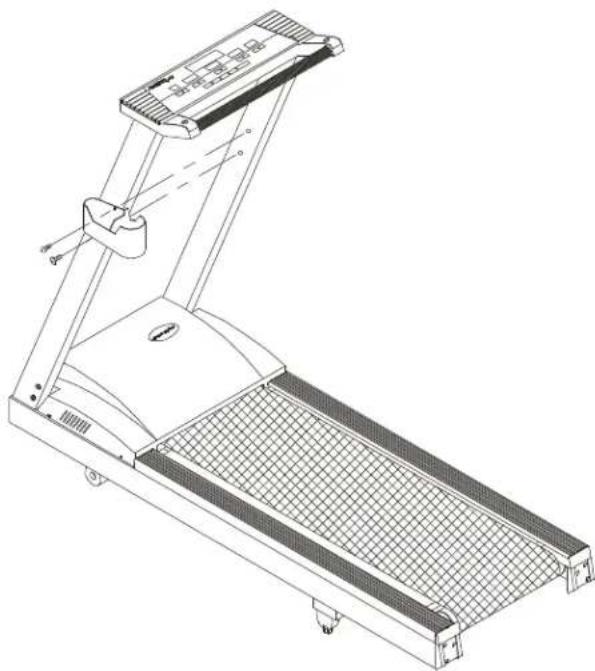
Assembling the water bottle/personal stereo holder:
Assemble the water bottle/personal stereo holder to the right post using two screws provided.
natural_image
Technical line drawing of a treadmill with mesh grille and control panel (no text or symbols)Fixedview:

natural_image
Line drawing of a treadmill with mesh grille and control panel (no text or symbols)- Lay the treadmill on its side. Make sure the running belt is in position in the tracks of the BELT ALIGNMENT GUIDE on the underside of the machine (see Fig.2).

natural_image
Technical line drawing of a mechanical assembly with no visible text or symbolsFig.2
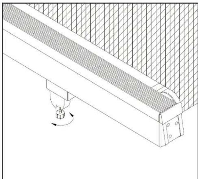
Floor level adjustment
If the treadmill is unsteady on your floor, turn the floor level adjustment on the rear feet of the treadmill. Raise or lower the floor level adjustment to steady your treadmill (see Fig. 3).
natural_image
Technical line drawing of a mechanical assembly with a rotating component (no text or symbols)Fig.3
MODES OF OPERATION
MANUAL:
As soon as you turn on the machine, it will go straight into the "MANUAL" mode. The speed LED will flash, press the SPEED key to start the treadmill, and the INCLINE keys to raise or lower the treadmill. If you don't push any keys within 3 seconds, the display will read "SELECT COURSE OR PRESS SPEED ▲▼ TO START".
In the MANUAL Mode, you can set the TIME of DISTANCE (but not both). Press either DISTANCE or TIME ▲▼ keys to set your desired workout time or distance.
The LED colors for MANUAL Mode is as follows:
Green LED: Tree (a way to gauge your speed)
Red LED: The current Elevation Percentage
Yellow LED: The Elevation Percentages you have finished
SET:
The treadmill allows you to customize your workout. This involves inputting your individual information (sex and weight). The treadmill can also register in either mile (MPH) or kilometers (KPH).
To set the USER values, you must press the MANUAL/SET key until SET appears in the display. Then press ENTER.
Selecting Miles or Kilometers:
You will be prompted to choose MPH or KPH.
Use any ▲▼ keys to select either choice, then press ENTER to record that choice.
Selecting Male or Female:
Next, you will be prompted to choose between "MALE/FEMALE". Use any ▲▼ keys to select your choice, then press the ENTER key to record that choice.
Selecting Weight:
Lastly, you will be prompted to "ENTER WEIGHT". After 4 seconds, a default weight (either 130 LB or 60 KG) will appear. Use any ▲▼ keys to change the weight.
Pressing the key once changes the weight 1LB or 1 KG. Holding the key down will change the weight 10 LB or 5 KG every 0.5 seconds. The weight range available is 50 - 440LB and 22 - 200KG. Press the ENTER key to record your weight, this will return you to the MANUAL mode.
WORKOUTOPTIONS
The 6005 treadmill offers a variety of workout options.
INTERVAL 1:
The Interval Workout Mode allows you to vary between work and rest periods. You specify the speed, incline and duration for both work and rest, then the treadmill will cycle between these until your desired Total Time.
Choose the INTV 1, then press ENTER, and the LED will display INTV 1. If this is the interval program you want, press ENTER. The message: "INPUT REST SPEED & INCLINE & TIME, THEN PRESS ENTER" will scroll through. Press ENTER, Then:
a. REST will appear in the center display.
b. You can use the speed ▲▼ keys to set the speed.
c. You can use the incline ▲▼ keys to set the incline.
d. You can use the time ▲▼ keys to set the time (in seconds).
e. Once you have set your desired REST loads, press ENTER to record them.
After the REST loads have been set, the display will read INPUT WORK SPEED & INCLINE & TIME, THEN PRESS ENTER. Please refer to REST load setting Instructions to alter the WORK load settings. WORK will appear in the center display. Once you have set your desired WORK loads, press ENTER to record them.
At any time during your workout, you may change the REST or WORK SPEED by using the ▲ or ▼ key under the SPEED display window. You may change the REST or WORK INCLINE by using the ▲ or ▼ keys under the INCLINE display window.
When the REST workout is over, the display will show "GOING TO WORK LOAD" and then the machine will adjust to the settings you chose for the work load (speed and incline). When the WORK TIME is over, the display will show "GOING TO REST LOAD", and return to the settings you chose for the rest load.
Keep in mind that the limits are as follows:
SPEED is from 0.1 mph - 12 mph (0.2kph - 19kph)
INCLINE is from 0 - 15%
Rest/Work TIME is from 60 - 990 seconds.
INTERVAL 2:
Interval 2 allows you to design your own personalized workout program. There are Eight programmable segments in Interval 2. Press the INTERVAL key until you see INTV 2 in the window, then press ENTER.
You will be prompted to INPUT SEGMENT 1 SPEED & INCLINE & TIME, THEN PRESS ENTER, and SEG 1 will appear in the LED window.
a) You can use the speed ▲ or ▼ keys to change the speed.
b) You can use the incline ▲ or ▼ keys to change the incline.
c) You can use the ▲ or ▼ key to change the time (in second).
After you have set SPEED & INCLINE & TIME, press ENTER. SEG 2 will now appear in the window. For Segments 2-8, please refer to the instructions above. Once all segments are set, press ENTER one last time, and your own personalized program, under INTV 2, will be recorded. If you only want to set four segments, leave segments 5 with values of zero, and the treadmill will use only your desired four segments.
While you are using INTERVAL 2, you may change the speed and incline at any time during your workout.
PRE-PROGRAMMED COURSES:
The treadmill features a total of twelve (12) professionally designed workout programs. The programs control the elevation, while you control the speed of your workout. During the actual programs, you cannot change the elevation percentage, but you can change the speed of the treadmill.
Press the PROGRAM key to scroll between the 12 programs. When you have chosen the Program you want, press the ENTER key. You will be prompted to INPUT TIME OR DIST, and both time and distance displays will flash. Use the TIME or DIST ▲▼ keys to select your desired DIST or TIME (but not both), then press ENTER.
The program profile will be displayed in the large central LED window, and will begin when you start the unit using the speed arrow keys. While the program profile is displayed, the speed display will flash, reminding you to begin the program by pressing the SPEED keys.
If you do not press the SPEED keys to begin the program, the display will read PRESS SPEED ▲ or ▼ TO START. During these programs, you control the speed, and the unit will automatically switch between elevation percentages, giving you the feeling of running on hills and level ground.
The course profile for each PROGRAM is as follows:
RACE:
The RACE Mode is an opportunity to test your fitness level by competing against the treadmill computer. Using the RACE Mode is an exciting way to gauge your fitness level, and chart your progress. Each of the LEVELS has a different distance, and the computer speed varies from level to level.
In the RACE Mode, choose between LEVEL 1 - LEVEL 8 by pressing the RACE button repeatedly, then press ENTER to choose your desired level: LEVEL 1 is the easiest, while LEVEL 8 is the most difficult.
For example, when you first begin exercising, it may be difficult to beat the computer at LEVEL 1, but after a month or so of regular workouts, you may finally be able to beat LEVEL 1. So, you go on to LEVEL 2 for an increased challenge. Each level has a different profile, and a different distance.
In RACE Mode, you are competing against the computer. The green LED represents the computer, while the yellow LED represents you. The red LED lights are the RACE course profile. If the green LED is ahead of the yellow LED, that means you are behind and should speed up. Your goal is to overtake the green LED and to be ahead when the RACE is over.
Here are the RACE LEVEL profiles:
For the last 0.2 Km / 0.1 Miles, the machine will BEEP to tell you the finish line is approaching. Time to start your kick!
At the end of the RACE, if you are behind, the display will read YOU LOST THIS TIME! TRY AGAIN! If you are ahead, you have won the race, and the display will read CONGRATULATIONS! YOU WON! TRY ANOTHER LEVEL.
After the RACE, there is a COOL DOWN period that corresponds to the length and speed of your RACE.
Every 30 seconds during the RACE, the display will show the COMPUTER SPEED for 4 seconds, then return to the RACE display.
During the RACE, each display light segment represents 0.1 Km / 0.06 Mile.
RUNNING ON THE TREADMILL
Now, you have become familiar with your treadmill's operation and are ready to exercise:
- Plug the treadmill into a standard outlet. Turn on the opower switch located on the front of the machine.
- Straddle the belt with your feet on the right and left staging platforms. Select your course and follow the scrolled messages. You may also PRESS the SPEED keys to begin.
- Stand on the belt, balancing one hand on the front of handrail. Press speed ▲ key until you reach 1.5 - 2.0 mph / 2.5 - 3.5 kph or a comfortable walking speed, keep both hands on the handrails, and walk for a few minutes to get comfortable with your machine.
- After you are walking in an easy, relaxed, and steady fashion, now release your grip on the handrails, and let your arms swing freely and naturally.
- When you feel comfortable walking, you may wish to jog. Hold the handrail with one hand, use the other hand to increase the speed for jogging.
- Remember to hold the handrail when using the control panel on the electronics package, or to catch your balance when slowing down or stopping, and for dismounting.
- When you have finished your workout, just press the STOP key located on both sides of the handrail. Remember to cool down before you end.
MAINTAINING TREADMILL
Your treadmill relies on low friction for peak performance. The treadmill's low friction operation is dependant on keeping the unit as clean as possible. See "Cleaning the Treadmill" for more information.
Proper belt alignment is also important for proper operation of the treadmill. See "Adjusting the Running Belt" for more information.
Cleaning the treadmill
CAUTION: Turn off the unit and disconnect the AC cord before cleaning.
Regular cleaning is recommended to keep your treadmill running at peak performance.
Before your workout, use a dry cloth to clean the landing platform, exposed slider bed, and under the belt as far as you easily reach. This removes any dirt or dust which might enter the slider area and compromise the unit's running efficiency.
To clean the plastic parts, use a mild detergent and make sure the unit is completely dry before operating. On the running surface, use a soft nylon scrub brush. Do not use water to clean the belt or running surface, or to clean the electronics package. Should water, for some reason, get on the electronics package, immediately blow dry the electronics package.
It is recommended that you keep all liquids away from the unit during operation. Spillage of liquids onto or into the machine will void the warranty.
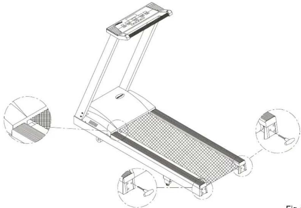
Adjusting the running belt
Your treadmill comes with a belt alignment gauge located on the left side of the motor cover (see Fig.4). The edge of the running belt should be in the middle of the green portion of the gauge. If the belt edge is in the green area, the belt does not need adjusting. If the right edge is in the red portion, the belt needs adjusting immediately.
natural_image
Technical line drawing of a treadmill with three inset views showing internal components (no text or symbols)Fig.4
The belt is properly aligned at the factory. However, during shipping and handling or by use on an uneven surface, the belt may move off center. Therefore, it is important that you check the belt's alignment before using the treadmill.
The correct alignment of the running belt is critical for the smooth operation of the treadmill.
NOTE: For increased safety, please shut the unit off while adjusting or working near the rear roller.
CAUTION: DO NOT ALLOW ANYONE TO WALK ON RUNNING BELT DURING THIS PROCEDURE.
Failure to realign the belt could result in tearing or fraying of the belt, which is not covered in the warranty. Please follow the adjustment procedure listed below:
- Turn on the power switch located on the front of machine.
- Press the SPEED ▲ key to increase the speed until the speed registers 2.0mph / 3.2kph on the digital display.
- While the unit is running at 2 mph / 3.2kph, determine where the belt is in relation to the belt alignment gauge.
-
Should your belt be in the wrong color range, follow the steps below to return the belt to the "safety zone".
-
If the belt is in the left red zone: Stop the machine, turn the left belt adjustment bolt located at the rear of the treadmill clockwise 1/4 turn at a time, using the hex Allen wrench. Then turn the right belt adjustment bolt counterclockwise 1/4 turn. Let the treadmill run 30 seconds, then check the position of the belt in the color gauge. If the belt still has not returned to the green safety zone, repeat with another 1/4 turn until the belt has returned to the middle of the green area. Do not turn adjusting bolt more than 1/4 turn at a time.
If the belt is on the edge of the green color, please adjust it so it is in the middle of the green color. You may turn the adjustment bolt less than 1/4 turn at a time.
-
Conversely, if the belt is in the right red zone, turn the right belt adjustment bolt clockwise 1/4 turn, then turn the left adjustment bolt counterclockwise 1/4 turn. Then let the treadmill run at least 30 seconds, check the position of the belt in the color gauge. If it still has not returned to the green safety zone, repeat with another 1/4 turn until the belt return to the middle of the green area. Do not turn adjusting bolt more than 1/4 turn at a time.
-
When the belt is back in the green "safety zone", you can continue your regular use of the treadmill. Slowly increase the speed of the unit to 5.5 MPH (9 KPH), and let it run for at least 45 seconds.
Periodically monitor the position of the belt to ensure peak performance:
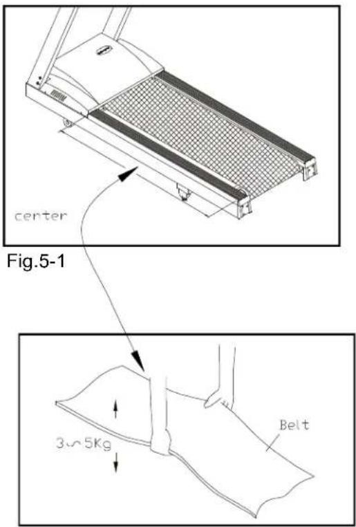
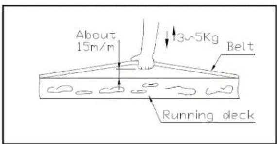
When you are using the treadmill, if you feel a pause in the belt with each foot plant the belt is too loose. Stop the machine, check the belt tension, left the running belt off the deck in the middle (see 5-1 & 5-2). There should be about 15m/m (5/8") or 3-5 kgs of "give" in the belt. If there is too much (see Fig.5-3), then adjust both rear roller bolts clockwise 1/2 turn at a time.
text_image
center Fig.5-1 3~5Kg BeltFig.5-2
text_image
About 15m/m 13~5Kg Belt Running deckFig.5-3
Then, try the belt tension again, if more adjusting is required, give both adjusting bolts another slight turn. Do not adjust over 2 fullturns.
Conversely, if the "give" in the belt is too tight, adjust both rear roller bolts counterclockwise 1/2 turn at a time.
CAUTION: To avoid injury, special care must be taken when adjusting the running belt. Turn off the treadmill while adjusting or working near the rear rollers. Remove any loose clothing or shoe laces and tie back your hair. Be very careful to keep your fingers or any other objects clear of the belt and rollers.
The treadmill is designed to carry specific weights at specific speeds. The treadmill will not stop immediately if any object becomes caught in the belt or rollers.
Over tightening of the belt causes damage and premature failure of the precision bearings in the front and rear rollers.
TROUBLE SHOOTING:
ERR message
ERR 1- The optical switch mounted on the motor is not receiving the signal reflected from the tachometer whel. Please contact your dealer.
ERR 2- The wires on the connector may be disconnected, please check that all the wires are connected securely.
ERR 3- Treadmill speed doesn't match the setting. Contact your local dealer for assistance.
ERR 5- The electrical frequency in your area is unstable, please turn "OFF" the machine and turn "ON" again. If the unit still fails to respond, please contact your dealer.
ERR 6- The unit's incline system may be damaged, please contact your dealer for more information.
ERR 7- The electronics package is receiving the signal reflected from the VR incorrectly, which means the terminal wires are disconnected, or the VR is damaged.
ERR 8- The electronics package CPU communication is disabled: please contact your dealer for more information.
ERR 9- When the treadmill has been run 30,000 Miles (48,000Km), the display will show ERR 9.
Or you may press DISTANCE ▲ key to temporarily disable the ERR 9 message.
Fuse failure for electronics package and motor
If nothing is displayed on the electronics package, please check the POWER switch located on the front for the treadmill. If it is unlit, then the fuse is damaged and must be replaced.
MAKE SURE THE TREADMILL PLUG IS REMOVED FROM OUTLET CAUTION: BEFORE REPLACING THE FUSE.
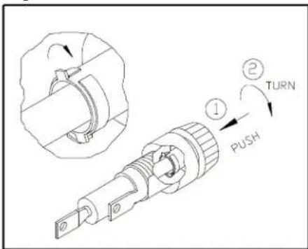
The fuse holders 1 amp/100-120 volts (or 0.5 amp/220-240 volts) for the incline system & 20 amp/100-120 volts (or 10 amp/220-240 volts) for the electronics package and motor are located under the frame at the front of the machine. (See Fig.6-1\~6-4). To remove the fuse for the electronics package and motor, push on the fuse holder and then turn the holder counter-clockwise and the fuse holder with fuse will protrude. Remove the damaged fuse and insert a new fuse, pushing the fuse and holder in, then turning clockwise to secure the fuse holder.
If the unit's electronics package or motor refuses to respond after changing the fuse, please contact your dealer for more information.

text_image
FUSE(100V-120V=20A) (220V-240V=10A) ELECTRONICS PACKAGE & MOTOR FUSE(100V-120V=1A) (220V-240V=0.5A) INCLINE SYSTEMFig.6-1

text_image
REMOVE THE DAMAGED FUSE AND INSERT A NEW FUSE.Fig.6-3
text_image
Technical diagram showing a mechanical component with labeled parts including 'PUSH', 'TURN', and numbered callouts ① and ②.Fig.6-2

text_image
Technical diagram showing a mechanical component with labeled parts including 'TURN', 'PUSH', and numbered callouts ① and ②.Fig.6-4
Fuse failure for incline system
NOTE: The 1 amp fuse is for 100 volt-120 volt current. The 0.5 amp fuse is for 220 volt-240 volt current.
Should the incline system refuse to respond, but there is power to the electronics package and it remains operable, please replace the incline system fuse.
Fuse Failure For drive board
NOTE: If you are not a technician or do not have expert knowledge of this machine. Please do not attempt to replace it.
If there is nothing displays on the electronics package, and the POWER SWITCH located on the front of the treadmill if lit, then the fuse is damaged on the drive board and must be replaced.
The fuse holder 0.5A (100V/120V) or 0.5A (200V/240V) for the drive board is located on the frame at the front of the treadmill (see Fig.7)

natural_image
Technical line drawing of an electronic device showing internal components and a 0.5A fuse (no text or symbols present)Fig.7
Wiring Schematic:

flowchart
graph TD
    A["PHOTODI-TERRIPTERS"] --> B["Driver Board"]
    B --> C["AC MOTOR"]
    B --> D["AC1 BLACK"]
    B --> E["AC2 WHITE"]
    B --> F["BROWN"]
    B --> G["Switch"]
    G --> H["AC POWER"]
    G --> I["Transformer"]
    B --> J["DC MOTOR"]
    B --> K["Capacitor"]
    B --> L["BROWN"]
    M["GREEN"] --> N["AC MOTOR"]
    M --> O["AC1 BLACK"]
    M --> P["AC2 WHITE"]
    Q["Upper Electronic Assy"] --> R["Connector"]
    R --> S["REFRATING"]
    T["Driver Board"] --> U["Driver Board"]
    U --> V["AC Motor"]
    U --> W["AC1 BLACK"]
    U --> X["AC2 WHITE"]
    Y["BROWN"] --> Z["Switch"]
    Z --> AA["AC POWER"]
    Z --> AB["Transformer"]
    AC["6005"] --> AD["AC Motor"]
    AE["6005"] --> AF["AC1 BLACK"]
    AG["6005"] --> AH["AC2 WHITE"]
    AI["6005"] --> AJ["AC Power"]
    AK["6005"] --> AL["AC Motor"]
    AM["6005"] --> AN["AC1 BLACK"]
    AO["6005"] --> AP["AC2 WHITE"]
    AQ["6005"] --> AR["AC Power"]
    AS["6005"] --> AT["AC Motor"]
    AU["6005"] --> AV["AC1 BLACK"]
    AW["6005"] --> AX["AC2 WHITE"]
    AY["BROWN"] --> AZ["Switch"]
    BA["BROWN"] --> BB["AC Motor"]
    BC["BROWN"] --> BD["AC1 BLACK"]
    BE["BROWN"] --> BF["AC2 WHITE"]
    BG["BROWN"] --> BH["AC Power"]
    BI["BROWN"] --> BJ["AC Motor"]
    BK["BROWN"] --> BL["AC1 BLACK"]
    BM["BROWN"] --> BN["BROWN"]
    BO["BROWN"] --> BP["BROWN"]
    BP --> BQ["BROWN"]
Your Authorized SPORTS ART Distributor