3110 - Tapis de course SportsArt - Notice d'utilisation et mode d'emploi gratuit
Retrouvez gratuitement la notice de l'appareil 3110 SportsArt au format PDF.

Questions des utilisateurs sur 3110 SportsArt
0 question sur cet appareil. Repondez a celles que vous connaissez ou posez la votre.
Poser une nouvelle question sur cet appareil
Téléchargez la notice de votre Tapis de course au format PDF gratuitement ! Retrouvez votre notice 3110 - SportsArt et reprennez votre appareil électronique en main. Sur cette page sont publiés tous les documents nécessaires à l'utilisation de votre appareil 3110 de la marque SportsArt.
MODE D'EMPLOI 3110 SportsArt
SPORTSART
3110 PerformanceSeries

text_image
OWNER'S MANUAL ASSEMBLY INSTRUCTION SPORTS/IRTOWNER'S MANUAL
ASSEMBLY INSTRUCTIONS
TABLEOF CONTENTS
- SAFETY GUIDELINES.... 1
- ASSEMBLING YOURTREADMILL InstallationRequirements.... 2 Listofparts.... 3 Stepbystepinstructions.... 4 Floor level adjustment.... 8
- OPERATINGINSTRUCTIONS Safety key.... 9
- UNDERSTANDING THE ELECTRONICS PACKAGE MANUALmode.... 10 INTERVAL course.... 11 PROGRAMmode.... 12 HRC 65% mode / HRC 80% mode.... 13
- KEY FUNCTIONS What each of the categories means.... 14
- RUNNING ON THE TREADMILL.... 16
- GUIDELINESFOREXERCISE How long should I exercise?...... 17 How oftenshouldlexercise?...... 17
- MAINTAINING YOURTREADMILL Cleaning the treadmill.... 18 Adjusting the running belt.... 19
- TROUBLE SHOOTING ERRMessages.... 22 ERR message for heart rate contact.... 22 Blank display.... 23 Electronicspackageand motorfusefailure.... 24
- Wiring schematic.... 25
SAFETY GUIDELINES:
Please read and follow the following safety guidelines:
Before beginning any exercise program, you should consult with your doctor. It is recommended that you undergo a complete physical examination.
- Read this owner's manual carefully and follow the instructions.
- Assemble and operate the treadmill on a solid, level surface. Keep the area behindthetreadmillclear.
- Never allow children on or near the treadmill. The running belt will not stop immediately if any object becomes caught in the belt or rollers.
- Check the treadmill before every use. Make sure all parts are assembled, and all nuts and bolts are tightened. Do not use the treadmill if the unit is disassembled inanyway.
- Keephandsawayfrommoving p arts.
- The weight limit for this treadmill is 300 lb. (135 kg).
- Wear proper workout clothing: Do not wear loose clothing. Do not wear shoes with leather soles or high heels. Tie back all long hair.
- Don't rock the unit from side to side. Care should be taken when mounting and dismounting t heunit.
- Straddle the machine with your feet on the right and left staging platform before starting t herunningbelt.
- Donotplaceanyliquidsonanypartofthetreadmill.
- To prevent shock, keep all electric components such as the motor, cord, and switchaway from water.
- Turn off the treadmill while adjusting or working near the roller.
- Do not use any accessories that aren't specifically recommended by the manufacturer, these might cause injuries or cause the unit to fail.
- Work within your recommended exercise level, do NOT work to exhaustion.
- If you feel any pain or abnormal sensation, STOP YOUR WORKOUT and consult yourphysicianimmediately.
The treadmill is designed for your use and enjoyment. By following the above precautions and using good judgment and commonsense, you will enjoy safe and pleasurable exercise with this treadmill.
ASSEMBLING YOUR TREADMILL:
Installationrequirements
Read this owner's manual and follow the instructions contained herein.
CAUTION: To avoid back strain, and to ensure safety to the unit and yourself, we suggest you may need a helper to remove the running deck assembly from box.
text_image
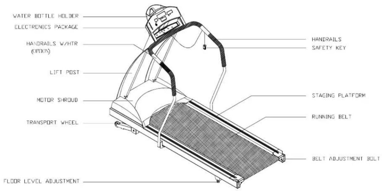
WATER BOTTLE HOLDER ELECTRONICS PACKAGE HANDRAILS W/HTR (OPTION) LIFT POST MOTOR SHROUD TRANSPORT WHEEL FLOOR LEVEL ADJUSTMENT HANDRAILS SAFETY KEY STAGING PLATFORM RUNNING BELT BELT ADJUSTMENT BOLTListof p arts
Before assembling your treadmill, make sure that you have all the following items:
- O ne s afetykey
- One hex Allen wrench (M6) with T-handle
- One hex Allen wrench (M5) with T-handle
- One hex Allen wrench (M5)
- One hex Allen wrench (M4) with T-handle
- One fuse - 15 amp for 100-120 volt use; 10 amp for 200-240 volt use
- Four M4 x L12 Philips screws - electronics package
- O ne 2 -wayScrewdriver
If any items are missing, contact your authorized service dealer.
IMPORTANT: The packing for this treadmill is designed to protect it during shipment. Please store the original packaging in a safe place in case you need to ship the treadmill in the future.
Stepbystepinstructions
The following steps explain how to assemble your treadmill. Please read every step thoroughly and follow the directions completely to ensure correct assembly.
-
There are important parts enclosed inside of the Styrofoam, please check the Styrofoam compartments before discarding. Make sure all packing materials are removed from the treadmill deck.
-
Lay the treadmill on its side. Make sure the running belt is positioned in the tracks of the two BELT ALIGNMENT ROLLER underside of the machine (see Fig. 1).

natural_image
Technical line drawing of a mechanical component with a meshed panel and inset detail (no text or symbols)-
Then, place the treadmill on a level, flat surface.
-
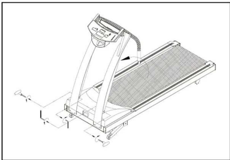
Bring the side post to their upright positions (including the handlebar and the electronics package). Attach the screws to the lift post. Do not tighten yet. (See Fig. 2)
natural_image
Technical line drawing of a treadmill with control panel and side-mounted legs (no text or symbols)Fig.2
- Using two 5/16" screws provided on each post. Do not tighten yet. (see Fig. 3)

natural_image
Technical line drawing of a treadmill with control panel and wheels (no text or symbols)Fig.3
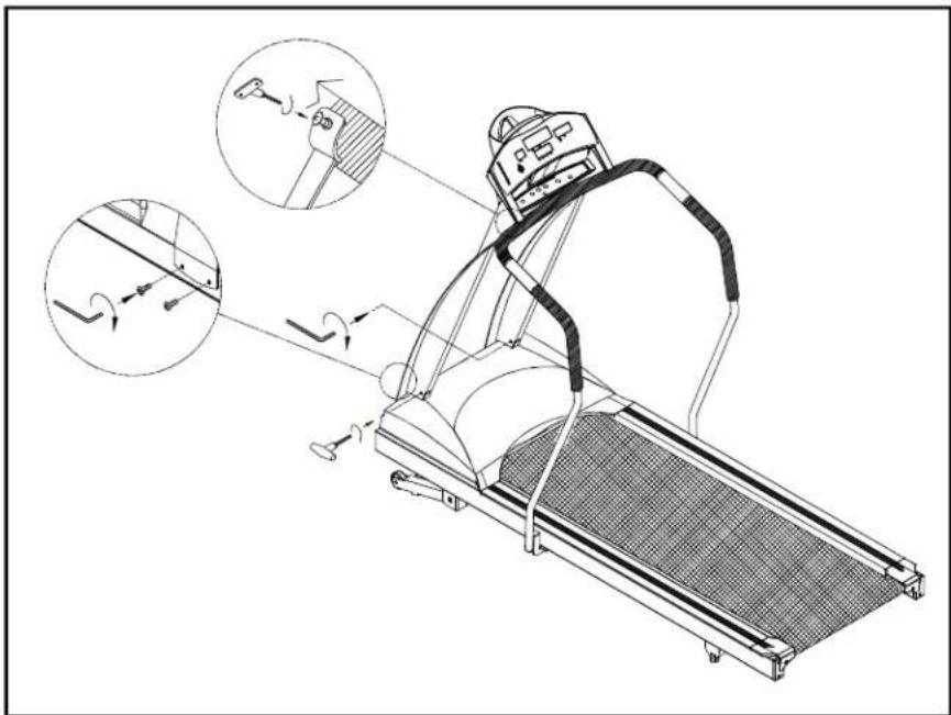
- Loosen the screws of fixing the handlebar and remove the steel plate. (see Fig. 4)

natural_image
Technical line drawing of a treadmill with an inset showing the internal mechanism (no text or symbols present)Fig.4
- T urnupthehandlebarandfastenthescrews. Donottightenyet.
If yourtreadmillisequipedwithHand TouchReadout(HTR), before fastening the screws, connect the wires from the display and the Hand TouchReadout handlebar securely, as shown in Fig 5. Then fasten the screws of the handlebar. Donottightenyet.

natural_image
Technical line drawing of a treadmill with two circular insets showing internal components (no text or symbols)Fig.5
Caution: Please make sure to connect the wires correctly, R to R and L to L which are marked on the wirest themselves.
Note: Theabovetwoscrewstothehandlebararespeciallyprovidedby manufacturer. Do not attempt to substitute any other screw.
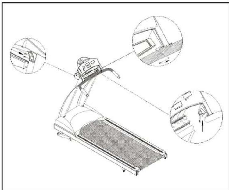
- Usethescrewdrivertotightenallscrewssecurely(seeFig. 6).
natural_image
Technical line drawing of a treadmill with three circular insets showing interior components (no text or symbols)Fig.6
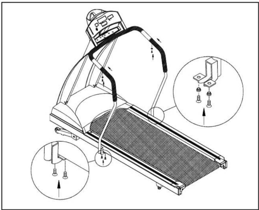
- Insert the two handrails into the handlebars and then fasten the screws provided. Lastly secure the handrail clamp by fastening the screws (see Fig. 7).
natural_image
Technical line drawing of a treadmill with mechanical components and mounting hardware (no text or symbols)Fig.7
Please note: The screws to the handrail clamp (Fig.7) are specially provided by manufacturer. Do not attempt to substitute any other screws. Any questions, please contact your dealer.
- Secure the screws in front of the lift posts and handlebar tightly, Secure the screws to the lift posts tightly (see Fig. 8).
natural_image
Line drawing of a treadmill with attached gear and control panel, showing motion capture insets (no text or symbols)Fig.8
Floorleveladjustment
If the treadmill is not steady on your floor, turn the floor level adjustment on the rear feet leg of the treadmill. Raise or lower the floor level adjustment to steady your treadmill(seeFig. 9).
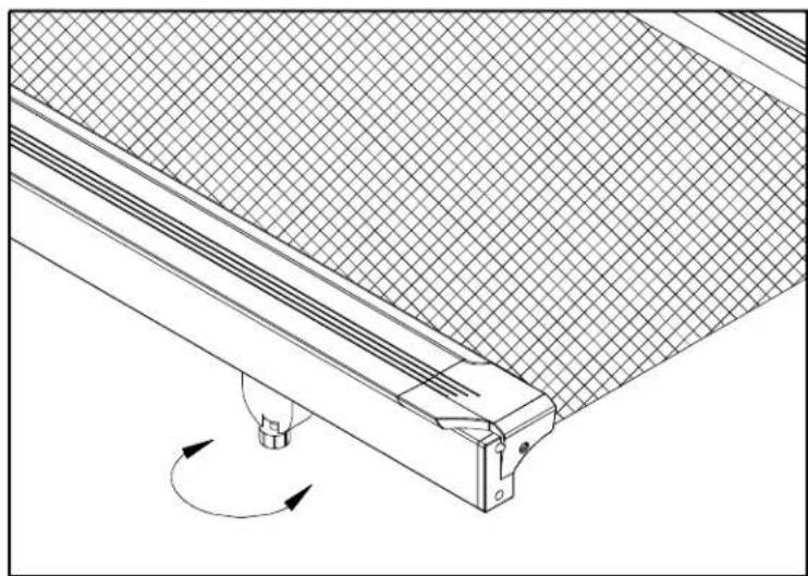
natural_image
Technical line drawing of a mechanical component with grid pattern and rotational arrow (no text or symbols)Fig.9
Your treadmill is assembled and ready to use.
OPERATINGINSTRUCTIONS
CAUTION: DONOTSTANDONTHEBELTWHENSTARTING.
Safetykey
Thesafetykeyisrequiredtooperatethetreadmill(seeFig.10). Thesafetykey shouldbeusedasanemergencystopbyclippingthecordtoyourexerciseclothing. Besuretostoreitin a safeplacetoavoidusebychildrenorpersonsunfamiliarwith thistreadmill.
Turnonthepowerswitchlocatedonthefrontofthetreadmill. Insertthesafetykey intothe"SAFETYKEY" positiononthemiddlesocketoftheelectronicspackagein orderfortheunittofunction.

natural_image
Technical line drawing of a mechanical device with no visible text or symbolsFig.10
UNDERSTANDINGTHEELECTRONICS PACKAGE
A. Turn on the power switch located on the front of the treadmill, then electronics will scroll through with the message "PLACE SAFETY KEY". The treadmill will not function without placingsafety key its position (see Fig.10).
B. After you put the safety key in place, the unit will scroll "SELECT MODE ▼▲ USER1- USER4". Or you can press SPEED ▼▲ keys to start the motor or follow upbelow stepstoinputyourdesireddata.
C. Use the ▼▲ keys to select from user 1 through user 4. Once you have made your choice, press "ENTER" to confirm your input. It will scroll through the message of SELECT MODE ▼▲ MPH/KPH". You can press the ▼▲ keys to choice mph or kph, then press "ENTER" to confirm your input. You will be prompted to input weight. If you choose mph or kph, the unit of weight is LB or KG respectively. Use the ▼▲ keys to set up the weight. Pressing the key once changestheweight1LB/1KG. Holdingthekeywill amendtheweight10LB/5KG every change. Then press "ENTER" to record them. The electronics package automatically recallstheprogramthatwasusedlast.
D. Press "Scroll" key to choose the desired program, such as Manual, Program, Interval, HRC—etc. The electronics display will automatically record what programyouchanged.
MANUALmode
A. Press "Scroll" key until Manual LED lights up. When "MAN'L" appears in the display window, and you will be in the MANUAL course.
B. Press the SPEED ▼▲ keys to start the motor. The speed range is 0.1-12 MPH(or 0.2-20KPH). Please press the SPEED ▼▲ eystoincreaseortodecreasethe speed.
C. Press the INCLINE ▼▲ keys to raise or lower the treadmill. The incline range is 0-15%.
D. Press the MODE key, and this will scroll you through the different modes on the smaller display window. With each press of the MODE key, the display will alternately show TIME, DIST(distance), CAL(calories), HR and SCAN.
INTERVALcourse
A. CustomInterval:
-
Press "Scroll" key until Custom Interval LED flashes and the larger display window will appear "INTV 1". If this is the interval program that you want, then press "ENTER". The message of "ENTER REST SPEED&INCLINE&TIME" will scroll through. RESTwillshowupinthecenterdisplay.
-
You can change your setting depending on your desired workout.
a. UsetheSPEEDkeys to change your desired speed.
b. You can use the ▼▲ keys to adjust your desired time. Time can be set from 60-255 seconds.
c. You can use the incline ▼▲ keys to change the incline as you want.
d. Once you have set your desired REST levels, press ENTER to record them. If you don't press ENTER to confirm your changes, you will be prompted to press ENTER.
-
After the REST levels have been set, the display will scroll through "ENTER WORK SPEED & INCLINE & TIME. WORK will appear in the center display.
-
You can refer to the REST setting instruction to alter the WORK settings. Once you have set your desired WORK levels, press ENTERtorecord them.
-
AfteryouhavesetyourdesiredRESTandWORKlevels, youwillbepromptedto ENTER TOTAL TIME. Use the ▼▲ keys to set your desired total time (from 00:00-99:00). Then press ENTER to confirm and to start the motor. Whenthetotaltimecountdownreaches00:00, theelectronicsdisplaywillbeepfor 10seconds.
-
When the REST TIME is over, the display will show "GOING TO WORK" and then themachinewillstartthesettingyouchoseforthework level(speedandincline). If you need to change any of the settings during your workout, please refer to step 2 as above. When the WORK TIME is over, the display will show "GOING TO REST", andreturntothesettingsthatyouchosefortherestlevels.
-
Press the MODE key to scroll the different modes on the smaller display window. Each press of the MODE key will alternately show TIME, DIST, CAL, HR or SCAN.
-
Keepinmindthelimitsasbelow: SPEEDrange:0.1-12MPHor0.2-20KPH INCLINE range:0-15% REST/WORK TIMErange:60-255seconds
B. CustomCourse
- Press "Scroll" key until Custom Interval LED flashes and the larger display window willappear"INTV2".
- Interval2allowsyoutodesignyouownpersonalizedworkoutprogram. Thereare eightprogrammablesegmentsinInterval2. Ifthiscourseiswhatyouwant, press ENTER, and you will be prompted to ENTER SEGEMENT 1 SPEED & INCLINE & TIME. Pleaseinputthespeed/incline/timeforSEGEMENT1.
S1willappearinthelargerLEDwindow.
UsetheSPEEDkeys setyourdesiredspeed.
Usekey▲tosetyourdesiredtime. Timerangeis0-99minutes.
UsetheINCLINE ▼▲keystosetyourdesiredinclineheight.
-
For segment 2-8, please refer to the instruction as above. Once all segments are set, press ENTER lastly to confirm the setting for INTERVAL 2.
-
Press the MODE key to scroll you through the different modes. With each press of the MODE key, the display will alternately show TIME, DIST, CAL, HR or SCAN.
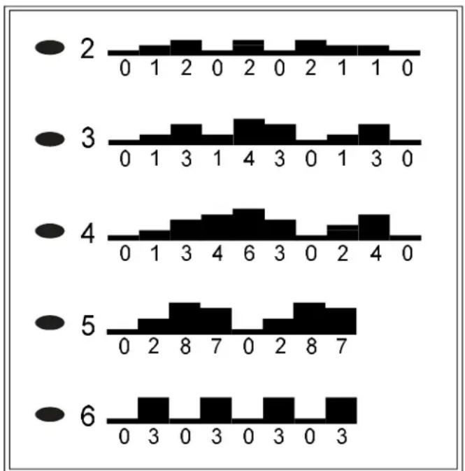
PROGRAMmode
A. Press "Scroll" key until pre-program LED flashes and the larger display window willappear"PRO:1\~PRO:5".
B. Therearefive(5) programsavailable.
Thecourseprofileforeachprogramisasfollows:
bar
| Category | Value 1 | Value 2 | Value 3 | Value 4 | Value 5 | Value 6 | |---|---|---|---|---|---|---| | 2 | 0 | 1 | 0 | 0 | 0 | 0 | | 3 | 0 | 1 | 3 | 0 | 0 | 0 | | 4 | 0 | 1 | 3 | 4 | 0 | 0 | | 5 | 0 | 2 | 8 | 7 | 0 | 0 | | 6 | 0 | 3 | 0 | 3 | 0 | 0 |C. When you have chosen the one that you want, press the ENTER key. You will be prompted to select DIST or TIME. Usethe keyst switches between DIST and TIME, then press ENTER to confirm your decision.
D. Usethekey to set your desired distance or time, then press ENTER.
E. The program will be displayed in the large LED window. The treadmill will start once you speed up by using the SPEED ▼▲ keys. You can control the speed during these programs, and the unit will automatically switch between elevation percentages, giving you the funny feeling of running on hills or climbing on the mountain.
F. Use the MODE key to switch between TIME, DIST, CAL, HR or SCAN on the LED window.
G. When you reach your desired TIME or DIST, the unit will beep for 10 seconds. After that the machine will directly count up if you continue your workout.
HRC-65% / HRC-80% mode (ifyourelectronicspackageincludestheHRCfeature)
A. Press "Scroll" key until HRC 65% or 80% flashes and the larger display window will appear "FAT" or "CARDIO".
B. When you press the ENTER key, it will scroll you the message of INPUT YOUR AGE, then it shows AGE 35. Please use ▼▲ keys to amend the age, the relative heart rate number will be changed accordingly. Input your exact age, press ENTER to scroll the message of "MODIFY YOUR HEART RATE LIMIT". Then it will appear MDFY on the window. Use ▼▲ keys to modify the target heart rate number, and press ENTER to confirm your modification. Then the TIME will appear on the window, press the MODE ▼▲ keys to set up the desired time for hearratecontrol. ThenpressENTERtoconfirmtheinput, the largerdisplaywill showuptheheartratemarkandthedesiredheartratefigure. PresstheSPEED ▼▲ keys to set the max. speed and start the motor. If there is no input of the heartrate, it'sunabletostartthetreadmill.
C. FormoredetailedinformationaboutHRCfunctionpleaserefertoHeartRate ControlOperationmanualasenclosed.
KEYFUNCTIONS:
SCROLL: Choose every function, such as Manual, Program, Interval and HRC.
SPEED: UsetheSPEEDkeysspeeduporslowdownthetreadmill. The speedrangeis0.1-12MPHor0.2-20KPH.
INCLINE: UsetheINCLINEkeysbraiseorlowerthetreadmill. Theincline rangeis0-15%.
MODE: Whenyouinsertthesafetykeyinitsplace, theelectronicspackagewill automaticallyaccessintoMODEfunction. PresstheMODEkeytoscroll youthroughthedifferentmodes. Witbeachpress, thedisplaywill alternately show TIME, DIST(distance), CAL(Calories), HR(heart rate), or SCAN.
▼▲ KEYS: These keys are used to choose the desired TIME, DISTANCE, USER, MPH/KPH/WEIGHT- - - etc.
SAFETY KEY: Turn on the power switch located on the front of the machine. Insert it into its position to operate the treadmill.
STOP: Press STOP key, the treadmill will come to stop gradually as pause function. Pressthiskeyonceagaintocontinuetheworkout. All data will be reserved. When the unit stops running, hold STOP key, thenalldatawillbecleared.
ENTER: confirmallinputinformation.
Whateachofthecategoriesmeans:
TIME: The range available in TIME mode is 00:00-99:59 minutes. Use the MODE key to select the time mode. When TIME LED is lit in the display, use the ▼▲ keystoadjustthedesiredtime. Each pressofthekeychangethetimeby 1 minute.
TheelectronicspackagewillBEEP for3secondswhenyourdesiredtimeis reached, thenwillstarttocountupifyouworkoutcontinues.
DIST: The distance of the treadmill will register goes from 0-99.99 miles or 0-999.9 kilometers. Use the MODE key to select the DIST mode. When DIST LED is lit in the display, use the ▼▲ keys to adjust the desired distance.
Each press of the key changesthedistance by 0.05 mile or 0.1 km.
RUNNING ONTHETREADMILL:
Now, you have become familiar with your treadmill's operation and are ready to exercise:
- T urnthepowerswitchON, andinsertthesafetykeyintothesocketofthe electronicspackage.
- Straddlethebeltwithyourfeetontherightandleftstagingplatforms. Clipthe safetykeytoyourexciseclothingatyourwaistline.
- Straddle the belt, balancing one hand on the handrail. Press SPEED key to start thetreadmill. Adjustthespeedkey ▲ntilyoureach1.5-2.0MPH / 2.5-3.2KPH, a comfortable walking speed. With both hands on the handrails, place one foot, thentheotheronthetreadmill, andwalkforafewminutestogetcomfortablewith yourmachine.
- After you are walking in an easy, relaxed, and steady fashion, release your grip on the handrails, and let your arm swing freely and naturally.
- When you feel comfortable walking, you may wish to jog. Hold the handrail with onehand, using your other hand to increase the speed.
- Remembertoholdthehandrailwhenusingthecontrolpanelontheelectronics package. Holdingthehandrailwithonehandwillhelptomaintainyourbalance, especially when slowing down or stopping. Also, remember to hold onto the handrailwhendismounting.
- When you have finished your workout, removethesafety key from the "SAFETY KEY" position. Always remember to cooldown your workout before completely stopping.
GUIDELINESFOREXERCISE
Howlongshould I exercise?
Thedurationofyourexcisesessionisdependentonyourfitnesslevel. Ingeneral, itisrecommendedthatyoumaintainyourheartrateinthetrainingzoneforatleast 10 minutes to realize an aerobic benefit. As your fitness level increases, you will be abletomaintainyourheartrateinthetrainingzoneforlongerperiods, usually between20and30minutes.
Whenfirststartingyourworkout, usethefirstseveralminutestowarmup, then slowlyincreaseyourworkloadtobringyourheartrateintoyourspecifictraining zone. At the end of your workout, gradually decrease your workload, then exercise lightlyasa"cooldown".
Howoftenshouldlexercise?
Aerobic exercises, to achieve the greatest benefits, should be performed 3-5 times a week. It is important to allow sufficient time, at least 24 hours, for your body to recoverafterexercise.
MAINTAININGYOURTREADMILL
Your treadmill relies on low friction for peak performance. The treadmill's low friction operation is dependent on keeping the unit as clean as possible. See "Cleaning the Treadmill" form more information.
Properbeltalignmentisalsoimportantforproperoperationofthetreadmill. See "AdjustingtheRunningBelt" formoreinformation.
Cleaningthetreadmill
CAUTION: TurnoffunitanddisconnectACcordbeforecleaning.
Regularcleaningisrecommendedtokeepyourtreadmillrunningatpeak Performance.
Before your workout, use a dry cloth to clean the staging platform, exposed slider deck, and under the belt as farasy you easily reach. This removes any dirtordust which might enter the slider area and compromise the unit's running efficiency.
To clean the plastic parts, use a mild detergent and make sure the unit is completely dry before operating. On the running surface, use a soft nylon scrub brush.
Donotusewatertocleanthebeltorrunningsurface, ortocleantheelectronics package. Should water, for some reason, get on the electronics package, immediatelyblowdrytheelectronicspackage.
It is recommended that you keep all liquids away from the unit during operation. Spillage of liquids onto or into them, machine will void the warranty.
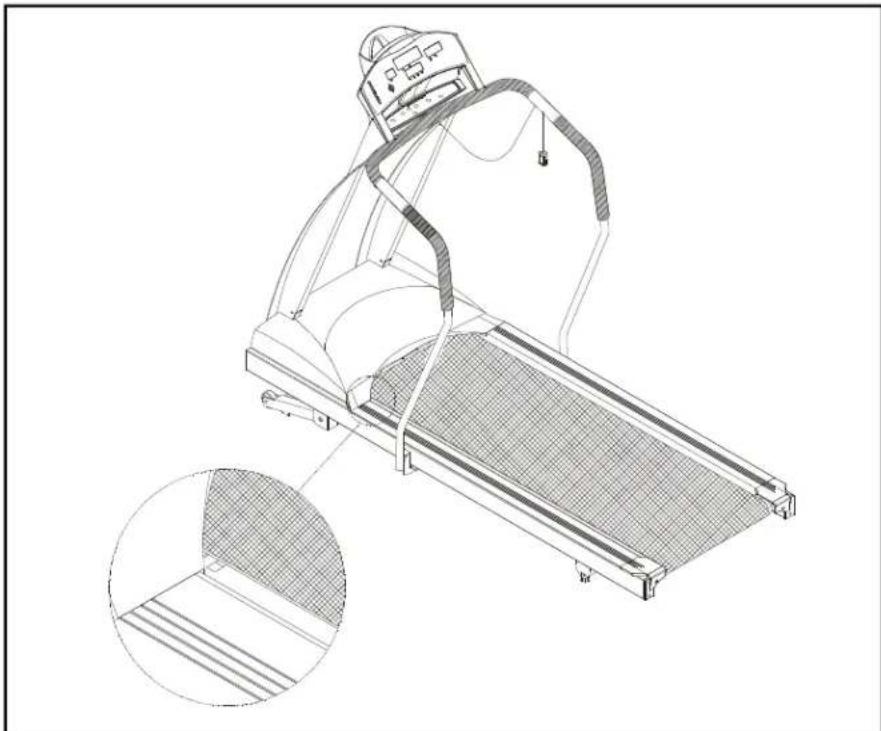
Adjustingtherunningbelt
Your treadmill comes with a belt alignment gauge located on the deck. (see Fig.11) Theedgeoftherunningbeltshouldbeinthemiddleofthegreenportionofthe gauge. If the belt edge is in the green area, the belt does not need adjusting. If the beltedgeisintheredportion, thebeltneedsadjustingimmediately.
natural_image
Technical line drawing of a treadmill with mesh cover and side view inset (no text or symbols)Fig.11
The belt is properly aligned at the factory. However, during shipping and handling or by use on an uneven surface, the belt may move off center. Therefore, it is important that you check the belt's alignment before using the treadmill.
Thecorrectalignmentoftherunningbeltiscriticalforthesmoothoperationofthe treadmill.
CAUTION: DO NOT ALLOW ANYONE TO WALK ON RUNNING BELT DURING THIS PROCEDURE.
Failure to realign the belt could result in tearing or fraying of the belt, which is not coveredinthewarranty. Pleasefollowtheadjustmentprocedurelistedbelow:
-
Turn on the power switch located on the front of machine. Insert the SAFETY KEY ontheitsposition.
-
Press the SPEED ▲ key to increase the speed until the speed registers 2.0mph / 3.2kphonthedigitaldisplay.
Periodically monitor the position of the belt to ensure peak performance:
When you are using the treadmill, if you feel a pause in the belt with each foot plant, the belt is too loose. Stop the machine to check the belt tension, pull the running belt up in the middle (see Fig. 12-1 & 12-2). There should be about 30 m/m (1 1/8") or 3 kgs of "give" in the belt (see Fig. 12-3). If there is too much, adjust both rear roller bolts clockwise 1/2 turn at a time (see Fig. 12-1). Then, check the belt tension again, if more adjusting is required, give both adjusting bolts another slight turn. Do notadjustover 2 fullturns.

text_image
About 30m/m (1-1/8Inch) 3Kg(6.6 Pound) Belt Running deck Fig.12-2 center Fig.12-3 3Kg(6.6 Pound) Belt Fig.12-1Conversely, if there is not enough "give", adjust both rear roller bolts counterclockwise1/2turnatatime.
CAUTION: To avoid injury, special care must be taken when adjusting the running belt. Remove any loose clothing or shoelaces and tie back your hair. Be very careful to keep your fingers or any other objects clear of the belt androllers.
The treadmill is designed to carry specific weights at specific speeds. The treadmill will not stop immediately if an object becomes caught in the belt or rollers.
Over tightening of the belt causes damage and premature failure of the precision bearings in the front and rear rollers.
TROUBLESHOOTING:
CAUTION: SHUTOFFUNITANDDISCONNECTACCORDBEFOREMAKING ANYREPAIRSORMODIFICATIONS.
"ERR" messages
Note: If the electronic display shows "E-1, E-3, E-7 or E-10", please turn off the POWERswitchonthefrontofthemachine. Allowtheunittorestfor5 seconds; thenturnonthepowerswitchbeginoperationagain. Shouldthe electronics package display "ERR" again, please refer to the following section formoreinformation. OR, pleasecontactyourdealerforfurtherinstructions.
E-1 Theopticalswitchmountedonthemotorisnotreceivingthesignalreflected from the tachometer wheel. Please contact your dealer.
E-3 The user is running faster than the belt. Please turn the POWER switch off, allow them machinetorest for 5 seconds, thentry normal use again.
E-7 The computer is receiving the signal reflected from VR incorrectly which means the wireshavebeendisconnected. Makesuretheribboncableisconnected securely, orcontactyourdealerforfurtherinformation.
E-10 Thetreadmillsuddenlyspeedsuptomaximumspeedwhileyouareusingit andshutsoff. Discontinueuseandcontactyourdealerforfurtherinformation immediately.
"ERR" messagesforcontactheartrate
TheE-12errormessagemayappearwhenusingthefeatureofHand TouchReadout (HTR). It doesn't effect the normal variety of functions of this product. When the messagedisappears, youarestillabletocontinuetoyourworkout.
E-12 If the electronics display shows E-12, the causes of this problem might be as below.
(1) Your heart rate cannot be read out due to the signal strength of your heart rate istooweakoryouhavelowbloodpressure.
(2) Your heart rate cannot be read out due to you did not place hands in steadycontactwithsensorswhendetectingyourheartrate.
- Replaceyourhandsafterwettingyour handsalittlebit. Pleasenotethatplacing yourhandsinsteadycontactwithsensorsisstrictlyrequired.
E-12willbeclearedoutafteritflashesorscrolls3timesandtheheartratewill become"0" automatically.
Blankdisplay
- IfyouturnonthePOWERswitchandthereisnolight:
a. Checkifthepowercordispluggedsecurelyintothewallsocket.
b. Check that the power switch on the front of the unit is in the "ON" position. The powerswitchshouldbelit.
c. If the power switch is not lit, replace the fuse. Please refer to the ELECTRONICS P ACKAGEANDMOTORFUSE F AILUREsectionformore information.
d. If there is still no display after completing the above steps, please contact your dealerformoreinformation.
- Thepowerswitchislit, butnowordsappearonthedisplay:
a. Makesurethecableconnectorsbothinsidetherightliftpostatthebaseofthe treadmillandatthetopofthepostarefirmlyintheirsockets.
b. If no words appear in the display, then the fuse on the drive board needs to be replaced, please check with your dealer for further information.
IfyouturnonthePOWERswitchandthereisnolight, andnothingdisplaysonthe electronicspackage, thenthefusemustbereplaced.
CAUTION: SHUTOFFTHEUNITANDDISCONNECTACCORDBEFORE MAKINGANYREPAIRSORMODIFICATIONS.
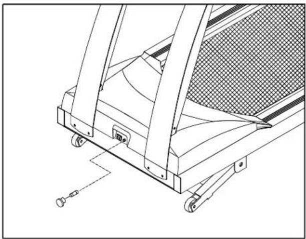
Thefuseholders15amp(100V-120V) / 10amp(200V-240V) fortheelectronics packageandmotorarelocatedonthefrontofthemachine. Pleasedetermineyour area'sstandardvoltagepriortoreplacement.
To remove the fuse for the electronics package and motor, push on the fuse holder and then turn the holder counterclockwise and the fuse holder with fuse will protrude. Removethedamaged fuse and insert a new fuse, pushing the fuse and holderin, then turning clockwise to secure the fuse holder. (See Fig 13-1 \~ 13-4)
natural_image
Technical line drawing of a mechanical device with wheels and a mesh panel (no text or symbols)Fig.13-1

text_image
Technical diagram showing a mechanical assembly with labeled parts including 'PUSH', 'TURN', and numbered callouts ① and ②.Fig.13-2

text_image
REMOVE THE DAMAGED FUSE AND INSERT A NEW FUSE.Fig.13-3

text_image
Technical diagram of a mechanical component with labeled parts and directional arrows indicating 'TURN' and 'PUSH'Fig.13-4
If the unit's electronics package refuses to respond after changing the fuse, please contact your dealer form more information.
WiringSchematic:
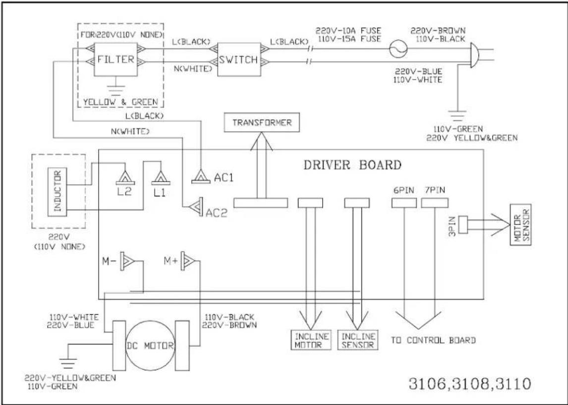
flowchart
graph TD
    A["FOR:220V(110V NONE)"] --> B["FILTER"]
    B --> C["L(BLACK)"]
    C --> D["SWITCH"]
    D --> E["L(BLACK)"]
    E --> F["220V-10A FUSE 110V-15A FUSE"]
    F --> G["220V-BROWN 110V-BLACK"]
    G --> H["220V-BLBlue 110V-WHITE"]
    H --> I["110V-GREEN 220V YELLOW&GREEN"]
    I --> J["110V-BLACK 220V-BROWN"]
    J --> K["AC1"]
    K --> L["AC2"]
    L --> M["TRANSFORMER"]
    M --> N["DRIVER BOARD"]
    N --> O["6PIN 7PIN"]
    O --> P["MOTOR SENSOR"]
    N --> Q["INCLINE MOTOR"]
    N --> R["INCLINE SENSOR"]
    N --> S["TO CONTROL BOARD"]
    T["INDUCTOR"] --> U["L2"]
    U --> V["L1"]
    V --> W["AC1"]
    W --> X["AC2"]
    X --> Y["AC1"]
    Y --> Z["AC2"]
    Z --> AA["AC1"]
    AA --> AB["AC2"]
    AB --> AC["AC1"]
    AC --> AD["AC2"]
    AD --> AE["AC1"]
    AE --> AF["AC2"]
    AF --> AG["AC1"]
    AG --> AH["AC2"]
    AH --> AI["AC1"]
    AI --> AJ["AC2"]
    AJ --> AK["AC1"]
    AK --> AL["AC2"]
    AL --> AM["AC1"]
    AM --> AN["AC2"]
    AN --> AO["AC1"]
    AO --> AP["AC2"]
    AP --> AQ["AC1"]
    AQ --> AR["AC2"]
    AR --> AS["AC1"]
    AS --> AT["AC2"]
    AT --> AU["AC1"]
    AU --> AV["AC2"]
    AV --> AW["AC1"]
    AW --> AX["AC2"]
    AX --> AY["AC1"]
    AY --> AZ["AC2"]
Your Authorized Distributor