
BWI 45 MDG - Elektrisk varmtvannsbereder BEKO - Gratis bruksanvisning og manual
Finn enhetens veiledning gratis BWI 45 MDG BEKO i PDF-format.


Brukerspørsmål om BWI 45 MDG BEKO
0 spørsmål om dette apparatet. Svar på dem du kjenner, eller still ditt eget.
Still et nytt spørsmål om dette apparatet
Last ned instruksjonene for din Elektrisk varmtvannsbereder i PDF-format gratis! Finn veiledningen din BWI 45 MDG - BEKO og ta den elektroniske enheten tilbake i hendene. På denne siden er alle dokumenter som er nødvendige for bruken av enheten din publisert. BWI 45 MDG av merket BEKO.
BRUKSANVISNING BWI 45 MDG BEKO

Electric Water Heater
User manual

natural_image
Simple line drawing of a droplet with a thermometer above it (no text or symbols)BWI 38 MDW
BWI 45 MDG
BWI 45 MDGR
Please read this user manual first!
Dear Customers,
Thank you for selecting an Beko product. We hope that you get the best results from your product which has been manufactured with high quality and state-of-the-art technology. Therefore, please read this entire user manual and all other accompanying documents carefully before using the product and keep it as a reference for future use. If you handover the product to someone else, give the user manual as well. Follow all warnings and information in the user manual.
Meanings of the symbols
Following symbols are used in the various section of this manual:

Important information and useful hints about usage.

WARNING: Warnings for dangerous situations concerning the safety of life and property.

Warning for electric shock.

Warning for fire.

Contents
- PARTS IDENTIFICATION....03
- IMPORTANT SAFETY INFORMATION....04
- DIAGRAM FOR HEATER UNIT INSTALLATION....05
- INSTALL THE HEATER UNIT....05
- RAINSHOWER ACCESSORIES INSTALLATION....06-07
- PLUMBING PROCEDURE....08
- ELECTRICAL INSTALLATION....09-10
- ELECTRICAL LOADING TABLE....10
- TEST RUN....11
- HANDSHOWER SPRAY ACTION....12
11.MAINTENANCE....12-13
12.WIRING DIAGRAM....13-14-15
13.ELECTRICAL SPECIFICATION.... 15
1 Parts identification

Note : (*) For PUMP MODEL only, For accessory depend on the model
Fig. 1
- Front Cover
- LED Indicators
- Test & Reset Button
- Pump Knob
- Temperature Control Knob
- Stop Valve
- Rail Support / Wall Bracket
- Handshower
- Adjustable Shower Holder
- Slider Rail
- PVC Hose
- Heater Base
- Thermostat
- Heater Tank
- PCB Board (Test & Reset)
- Terminal Block
- Main PCB Board
- Water Outlet Connection
- DC Pump
- TRIAC
- Water Inlet Connection
- Reed Switch Assy
- Mesh Filter
- Pump Control PCB Board
- SMPS Board
- Shower Bracket
- Soap Tray
2 Important safety information
Warning!
1.1 Products manufactured by us safe provided they are installed, used and maintained in good working order in accordance with our instruction and recommendations. Always refer to this manual if you have any doubt.
1.2 The appliance must be earthed. Improper grounding could cause lectic shock.
1.3 If any of the following conditions occur, immediately switch off the mains and contact the saled agent for repair. Never attempt to repair the unit yourself.
1.3.1 If the Heater begins to make an odd noise, smell or smoke.
1.3.2 ELCB and Heater lamp does not light up.
1.3.3 Water temperature can not be controlled.
1.3.4 If the Heater shows signs of a distinct change in performance/
1.3.5 If found water leakage from inside.
1.4 For pump Model, it is highly recommended to connect the Water Inlet Connection to tank storage supply otherwise it may cause damage to the Pump Motor.
1.5 When the Shower is used by someone such as child, elderly person, sick person and physically handicapped person, the concern person is kindly requested to pay attention and check the shower temperature by using hand from time to time. User is advised to test and adjust the water temperature before bathing.
1.6 In time of lightning/thunder, switch "off" the electric supply to the shower unit in advance to protect the shower unit against possible damage.
1.7 Metallic/chrome hose and conductive control valve shall not be used.
(Malaysia only)
Note: When removing the unit from package, small amount of water may found inside. This is normal as the unit is tested during manufacturing process.
Caution!
2.1 Installation must be carried out by a qualified personnel and in compliance to the local authority regulations.
2.2 This heater must be permanently connected to the direct main current supply. The use of a plug and socket is not recommended.
2.3 For the correct size of wire conductor corresponding to different electrical loading. Please refer to Table 1.
2.4 This heater operates at a minimum water flow rate of 2.0ltr/min and maximum working pressure of 6 bars.
For direct connection to the water tank, the heater must have a minimum of
1.0m below the water tank.
2.5 This heater will not function if there insufficient water flow (min 2.0ltr/min) to trigger the flow switch.
2.6 The built-in ELCB will automatic cut off the power supply in case there is a current leakage as low as 15mA.
2.7 The thermostat will automatic cut off the power supply if it has sensed an abnormal rise in showering water temperature.
3 Diagram for heater unit installation
Heater unit installation diagram

4 Install the heater unit
Heater Unit Installation (Fig. 2a)
- Select a suitable position in the bathroom.
- Pull out the Temperature Control Knob and then remove the screw (A) at the bottom of the unit.
- Remove the Front Cover from the bottom and then lift up the front cover.
- Insert the wall plugs and mount the Heater firmly in position with the screws provided.
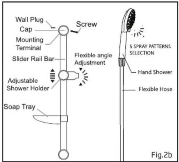
Shower Accessories with Sliding Rail (Fig. 2b)
- Mark 2 screw points of the Slider Rail beside the heater. It is recommended that the top of the portion is in level with the top of Heater.
- Use 6mm diameter drill and make the wall plug holes in depth of 34mm.
- Insert the Shower Holder and Soap Tray into the Slider Rail.
- Mount the Slider Rail to the Rail Bracket.
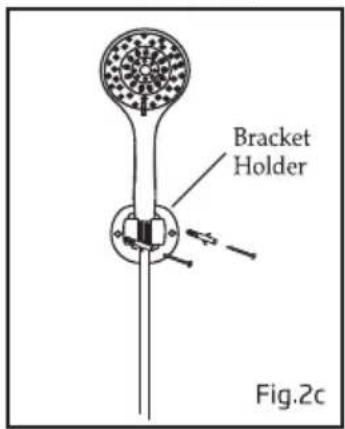
Shower Bracket Accessories (Fig. 2c)
-
Mark 2 screw points of the Shower Bracket beside the water heater.
-
Use 6mm diameter drill and make the wall holes in depth of 34mm
-
Screw the bracket to position.
5
Rain Shower Accessories Installation
Rail Bracket Cover and Cap Dismantle Steps


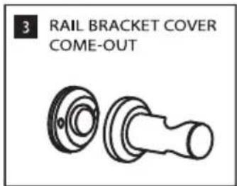
Step 1
Insert the Top Rail Bracket, Adjustable Shower Holder & Bottom Rail Bracket to the Slider Rail.

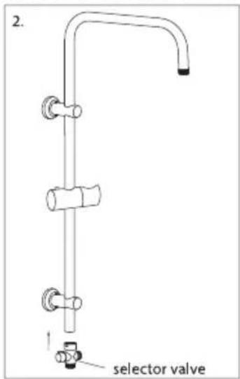
Step 2
Connect the Selector Valve to the bottom of the Slider Rail.
Step 3
Select a suitable position for the Rain Shower Set then mark 4 screw points (2 on top and 2 at bottom). The gap of 2 screw hole is 38mm. It is recommended that the Top rail Bracket is positioned at height of 1950mm from the floor and Bottom Rail Bracket 300mm from the floor.

Step 4
Use 6mm diameter drill and make the wall plug holes to 34mm depth. Insert the wall plugs and mounting terminal firmly in position with the screw provided.
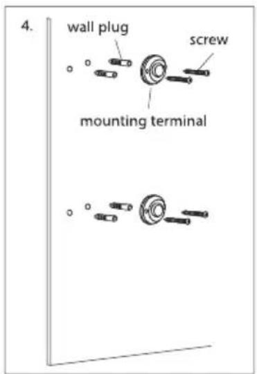
5 Rain Shower Accessories Installation
Step 5
Mount the Slider Rail (connected with Rail Bracket, Adjustable Shower Holder and Selector Valve) to the mounting terminal by turning the terminal cover.

natural_image
Pure technical diagram of a vertical pipe assembly with directional arrows indicating flow or movement (no text or symbols)Step 7
Recommended height for Rain Shower Set.

Step 6
Connect the Rain Shower Head to the top of the Slider Rail, 1.5 Meter PVC Hose to Hand Shower Head and 1 Meter PVC Hose to the Heater. Please make sure the Rubber Washer in inserted

6 Plumbing procedure
Caution!
For Single point heater, the 'Water Outlet' can only be fitted to the Hose and Handshower set provided. NO CONTROL VALVE OR FITTING CAN BE FITTED TO THE WATER OUTLET.
- Connect the Stop Valve to the Water Inlet with washer. Use correct tools to tighten and be careful not to over tighten and damage the plastic nut.
- Connect the incoming water piping (1/2" BSP) to the Stop Valve. Make sure to put the Mesh Filter between Stop Valve and incoming water piping.
- If any case, the Stop Valve is not use or omitted, make sure to put the Mesh Filter between the heater unit inlet pipe and incoming water pipe.
Important
For Pump model, it must never be connected to a Direct Main Water Supply, otherwise it will cause damage to the pump motor. It is recommended to connect the water supply from tank only.
-
Turn on the water mains to drain out all plumbing dirtis and to fill up the heater tank. THE HEATER TANK MUST BE FILLED UP WITH WATER BEFORE TURN ON THE ELECTRICITY SUPPLY. THIS IS TO PREVENT ANY DRY BURNT DAMAGE TO THE HEATING ELEMENT.
-
Connect the PVC Hose and Hand-shower to the outlet of the Heater, be sure to put in the water.
-
Hook the Handshower to the Slider Rail Shower Holder and adjust to your ideal position.
-
Check for any water leakage.
- Do not use white tape during installation.
Warning!
- THE WATER INLET AND OUTLET MUST BE INSTALLED CORRECTLY, OTHERWISE THE HEATER CAN NOT FUNCTION.
- DO NOT USE PLUMBING CEMENT ON CONNECTION. IF NECESSARY, USE ONLY THREAD OR SEALING TAPE.
7 Electrical installation
Warning!
- This appliance must be EARTHED. Improper grounding could cause electrical shock.
- Remember to SWITCH OFF at mains before carrying out any electrical work.
- Refer to the previous TABLE 1 for the correct cable size.
- Use double coated flexible cable having nominal cross-sectional area between 2.5mm². [§26.6, IEC/EN 60335-1]
- Lead the power cable from the MCB to a "ON/OFF" double pole linked switch having a contact separation of at least 3mm in all poles outside the bathroom, then lead a cable connected to terminal block inside the unit. (Fig.3)
Procedure:
- Insert the cable through 'A' for side entry or 'B' for wall embedded cable by cutting a hole through the source cord rubber holder. (Fig.4)
- Connect the cable to Terminal Block and fully tighten them as follow
BROWN or RED - LIVE (L)
BLUE or BLACK - NEUTRAL (N)
GREEN or GREEN/YELLOW - EARTH (⊕)
-
When replace back the Front Cover, please take note the below procedure:
-
To ensure the correct position, turn the Temperature VR Knob insert to OFF position as shown in Fig A. (at the Heater Base)
- To install the Front Cover, turn the Temperature Control Knob to OFF position to align with the VR Knob Insert as shown in Fig B. (at the Front Cover)
** For Pump Models, the same align procedure is apply to both Pump VR Insert and Pump Knob.
- Fix back the screw 'A'.


Fig. 4
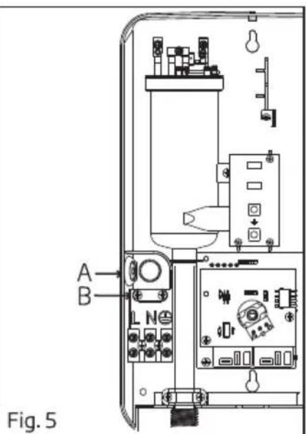
7 Electrical installation
Method of alignment when fixing front cover

Fig A

8 Table 1 - Electrical loading table
| Voltage (AC) | Power (kW) | Current (A) | Minimum Conductor Size (csa) | On/Off Switch (A) | Fuse / MCB (A) | ||
| mm^2 | Conduit Cable | Flexible Cable | |||||
| 240~50/60Hz | 2.5 | 10.4 | 2.5 | 7/0.67 mm | 50/0.25 mm | 20 | 20 |
| 3.3 | 13.8 | 2.5 | 7/0.67 mm | 50/0.25 mm | 20 | 20 | |
| 3.6 | 15.0 | 2.5 | 7/0.67 mm | 50/0.25 mm | 20 | 20 | |
| 4.0 | 16.7 | 2.5 | 7/0.67 mm | 56/0.25 mm | 20 | 20 | |
| 5.0 | 20.8 | 4.0 | 7/0.85 mm | 56/0.30 mm | 32 | 32 | |
| (Malaysia Model) | |||||||
| 3.6 | 15.0 | 4.0 | 7/0.85 mm | 56/0.30 mm | 20 | 20 | |
| 3.8 | 15.8 | 4.0 | 7/0.85 mm | 56/0.30 mm | 20 | 20 | |
| 4.5 | 18.8 | 4.0 | 7/0.85 mm | 56/0.30 mm | 32 | 32 | |
| 4.8 | 20.0 | 4.0 | 7/0.85 mm | 56/0.30 mm | 32 | 32 | |
| 230~50/60Hz | 2.4 | 10.4 | 2.5 | 7/0.67 mm | 50/0.25 mm | 20 | 20 |
| 3.0 | 13.0 | 2.5 | 7/0.67 mm | 50/0.25 mm | 20 | 20 | |
| 3.3 | 14.4 | 2.5 | 7/0.67 mm | 50/0.25 mm | 20 | 20 | |
| 4.0 | 17.4 | 2.5 | 7/0.67 mm | 56/0.25 mm | 20 | 20 | |
| 5.0 | 21.8 | 4.0 | 7/0.85 mm | 56/0.30 mm | 32 | 32 | |
| 220~50/60Hz | 2.4 | 10.9 | 2.5 | 7/0.67 mm | 50/0.25 mm | 20 | 20 |
| 3.5 | 15.9 | 2.5 | 7/0.67 mm | 56/0.25 mm | 20 | 20 | |
| 4.5 | 20.5 | 2.5 | 7/0.67 mm | 56/0.25 mm | 32 | 32 | |
| 5.5 | 25.0 | 4.0 | 7/0.85 mm | 56/0.30 mm | 32 | 32 | |
| 6.0 | 27.3 | 4.0 | 7/0.85 mm | 56/0.30 mm | 32 | 32 | |
9 Test run
- Turn on the water supply and Stop Valve, the water will flow through the Handshower.
- Switch on the electrical supply.
- Turn the Temperature Control Knob to 'ON', the Red Indicator light (HEATER) will turn on, hot water will flow out within a few seconds. The more Temperature Control Knob being turned in clockwise direction, the hotter is the shower.
- The shower might not be hot enough even at 'MAX' position if incoming water supply from the mains is too cold or pressure water is too high. In this case, you may adjust the Stop Valve to reduce the water inflow in order to get the desired showering temperature.
-
Check the Built-in ELCB as following:
-
Press the "TEST" Button, the Built-in ELCB should trip and cut off the power supply, all LED Indicators should light off.
- Press the "RESET" Button, the Heater Unit should resume normal function, the Green LED Indicators should light on.
If procedures stated above prevailed, the ELCB is functioning in notmal condition.
For Vietnam Models Only: The Unit has a Blue LED Indicator (EARTH) The Blue light will not light up when there is poor earth connection. Please contact licensed electrician for further assistance.
- It is unnecessary to turn the Temperature Control Knob to "OFF" Position when the Heater is not in use.
- Switch OFF the electricity supply after shower.
- For Pump Models: Turn on the Pump Control Knob to test on Pump's functionality. If the shower is not hot enough, you may adjust the pump speed until the desired shower temperature is obtained.

10 Handshower spray action
This innovative adjustable Handshower has different spray actions. The actions are described as follows.
Normal Shower Accessories

Clean the Handshower Head holes by using the soft brush from time to time. (Recommended once a week) Note: Take care not to damage the holes of the Handshower Head during cleaning.
11 Maintenance
Read the section 'IMPORTANT SAFETY INFORMATION' first.
1. TEST THE 'ELCB' REGULARLY
(This procedure is highly recommended test at least once a month) Turn on the electricity and water supply, the Green ELCB lamp will light up. If the Temperature Control Knob is in 'ON' position, the Red Heater lamp will light up also. Press the ELCB Test knob, the ELCB and HEATER lamp should go off. Press the Reset Knob to reseume back the electricity supply.
Warning!
If the ELCB or HEATER lamp does not go off when you press the ELCB Test Knob, SWITCH OFF the mains supply and contact your sales agent for repair. Special skill is required for repair. NEVER try to repair the unit by yourself.
11 Maintenance
2. CLEANING PRECAUTION!
Do not use thinner, alcohol, petrol or any other organic solution to clean the set, use only a damp cloth with mild detergent.
3. CLEAN THE FILTER REGULARLY (Fig. 8 & Fig. 9)
There are two filter located at the stop valve, one is Mesh Filter (installed at the incoming water supply), another one is the built-in filter as shown in Fig. 9). Clean the Mesh Filter regularly to prevent blockage. Remove the built-in filter by turn it anti-clockwise as shown in Fig. 8. Take out the Filter and flush it with water to remove any trapped sendiments. (as shown in Fig. 9)
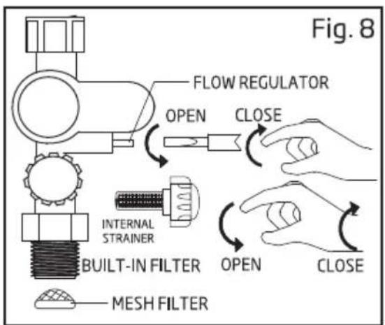
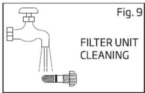
12 Wiring diagram
Wiring diagram - with elcb, no pump model (single element)
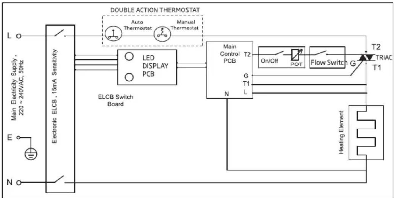
flowchart
graph TD
    A["Main Electricity Supply, 220~240VAC, 50Hz"] --> B["Electronic ELCB, 15mA Sensitivity"]
    B --> C["ELCB Switch Board"]
    C --> D["LED DISPLAY PCB"]
    D --> E["Main Control PCB T2"]
    E --> F["On/Off"]
    F --> G["POT"]
    G --> H["Flow Switch G"]
    H --> I["T2 TRIAC T1"]
    I --> J["Heating Element"]
    J --> K["N"]
    L["L"] --> M["Double Action Thermostat"]
    N["M"] --> O["Main Electric Supply"]
12 Wiring diagram
Wiring diagram - with elcb, no pump model (esp)
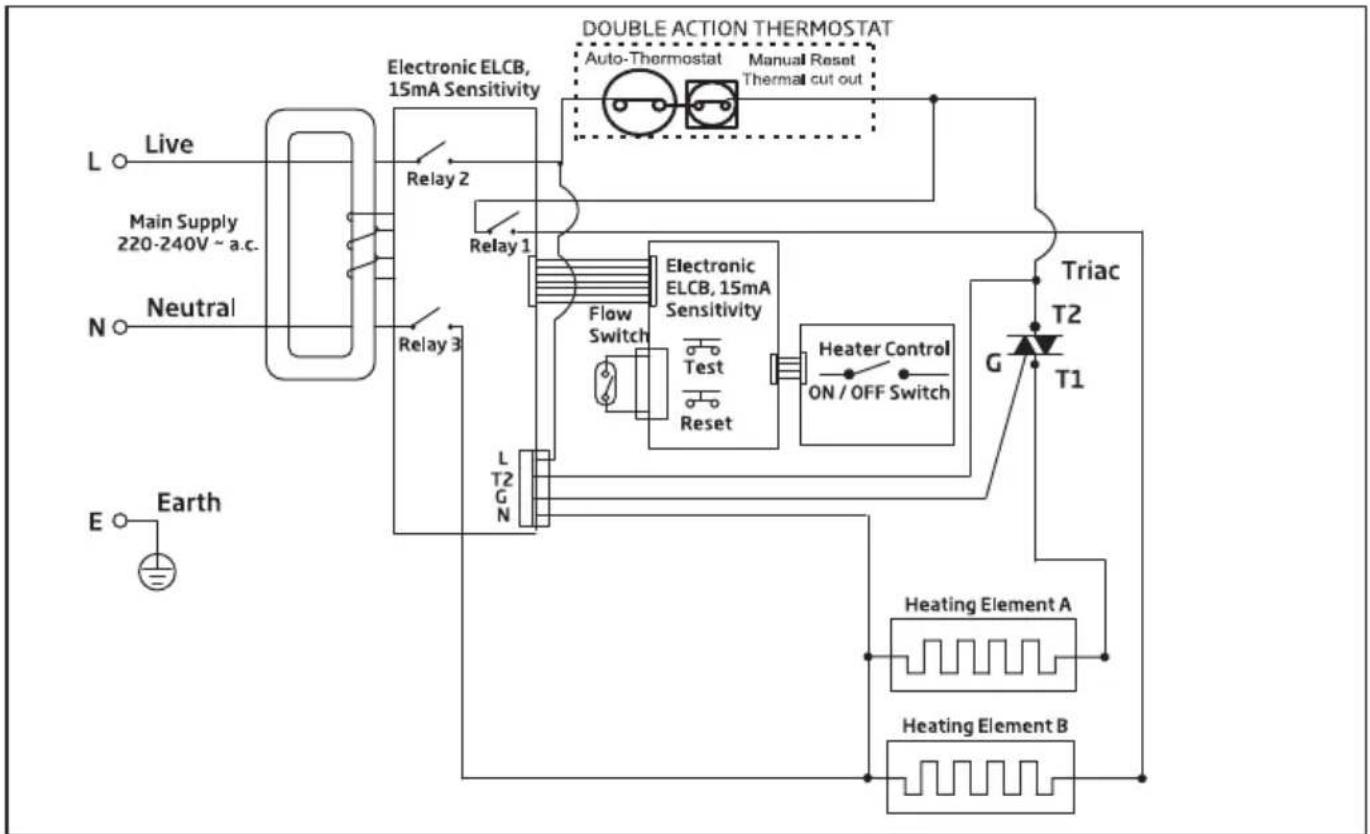
flowchart
graph TD
    A["Live"] --> B["Main Supply 220-240V ~ a.c."]
    B --> C["N Neutral"]
    C --> D["E Earth"]
    D --> E["L T2 G N"]
    E --> F["Relay 1"]
    F --> G["Electronic ELCB, 15mA Sensitivity"]
    G --> H["Double Action Thermostat"]
    H --> I["Auto-Thermostat"]
    H --> J["Manual Reset Thermal cut out"]
    G --> K["Flow Switch"]
    G --> L["Test Reset"]
    G --> M["Test Switch"]
    G --> N["Test Switch"]
    G --> O["Test Switch"]
    G --> P["Heater Control ON/OFF Switch"]
    G --> Q["Triac T2 T1"]
    Q --> R["G"]
    R --> S["Heating Element A"]
    R --> T["Heating Element B"]
Wiring diagram - with dpdt elcb, dc pump model* (esp)

flowchart
graph TD
    A["Live"] --> B["Main Electricity Supply 220~240VAC,50Hz"]
    B --> C["L"]
    C --> D["Neutral N"]
    D --> E["E"]
    E --> F["Earth"]
    G["Electronic ELCB, 15mA Sensitivity"] --> H["Relay 1"]
    G --> I["Relay 2"]
    H --> J["Heater Control ON/OFF Switch"]
    I --> K["Heating Element"]
    L["Triac"] --> M["T2"]
    M --> N["G"]
    N --> O["SMPS PCB ASSY"]
    P["T1"] --> Q["Pump Control ON/OFF Switch"]
    R["DOUBLE ACTION THERMOSTAT"] --> S["Auto-Thermostat Manual Reset Thermal cut out"]
    T[""ESP" Model"] --> U["SMPS PCB ASSY"]
    V["LED DISPLAY PCB"] --> W["Heater Control ON/OFF Switch"]
    X["Heating Element"] --> Y["Heating Element"]
    Z["Thermal cut out"] --> AA["Thermal cut out"]
12 Wiring diagram
Wiring diagram - with dpdt elcb, dc pump model* (esp)

flowchart
graph TD
    A["Main Supply 220-240V ~ a.c."] --> B["L Live"]
    A --> C["N Neutral"]
    A --> D["E Earth"]
    B --> E["Electronic ELCB, 15mA Sensitivity"]
    C --> F["Relay 2"]
    C --> G["Relay 3"]
    D --> H["Triac T2"]
    D --> I["G Triac T1"]
    J["Heating Element A"] --> K["Heating Element B"]
    L["Heater Control ON/OFF Switch"] --> M[""ESP" Model"]
    N["SMPS PCB ASSY"] --> O["Flow Switch"]
    P["Auto-Thermostat Manual Reset Thermal cut out""] --> Q["Double Action Thermostat"]
    R["Triac T2"] --> S["LED DISPLAY PCB"]
    T["Triac T1"] --> U["Thermal Cut Out"]
* Manual Reset (90 °C Thermostat)
For Models rated 4.5kW and below, thermostat is manually resetable.
13 Electrical specification
| TYPE | ELECTRONIC POWER CONTROL |
| ELECTRICAL LOADING | 2.4kW TO 6.0kW 220/230/240Va.c. 50/60Hz |
| Min. WATER FLOW RATE | 2 Liter / min. |
| Min. INLET WATER PRESSURE | 0.1 Bar (10kPa) |
| Max. INLET WATER PRESSURE | 6 Bar (0.6MPa) |
| WATER CONNECTION | 1/2" BSP SINGLE POINT SYSTEM |
| DIMENSIONS | 342 x 219 x 105 mm |
| WEIGHT | 1.65 Kg (No Pump)2.00 Kg (DC Pump) |
Note : The specification, actual product's cosmetic design and accessories parts shown are correct at the time of printing and may be subjected to change without prior notice.




- Electric Water Heater
- Please read this user manual first!
- Meanings of the symbols
- Contents
- Parts identification
- Important safety information
- Warning!
- Caution!
- Diagram for heater unit installation
- Heater unit installation diagram
- Install the heater unit
- Heater Unit Installation (Fig. 2a)
- Shower Accessories with Sliding Rail (Fig. 2b)
- Shower Bracket Accessories (Fig. 2c)
- 5
- Rain Shower Accessories Installation
- Rail Bracket Cover and Cap Dismantle Steps
- Step 1
- Step 2
- Step 3
- Step 4
- Rain Shower Accessories Installation
- Step 5
- Step 7
- Step 6
- Plumbing procedure
- Important
- Electrical installation
- Procedure:
- Test run
- Handshower spray action
- Maintenance
- TEST THE 'ELCB' REGULARLY
- CLEANING PRECAUTION!
- CLEAN THE FILTER REGULARLY (Fig. 8 & Fig. 9)
- Wiring diagram
Merke : BEKO
Modell : BWI 45 MDG
Kategori : Elektrisk varmtvannsbereder