VWA-01 - Veggfeste AG Neovo - Gratis bruksanvisning og manual
Finn enhetens veiledning gratis VWA-01 AG Neovo i PDF-format.

Brukerspørsmål om VWA-01 AG Neovo
0 spørsmål om dette apparatet. Svar på dem du kjenner, eller still ditt eget.
Still et nytt spørsmål om dette apparatet
Last ned instruksjonene for din Veggfeste i PDF-format gratis! Finn veiledningen din VWA-01 - AG Neovo og ta den elektroniske enheten tilbake i hendene. På denne siden er alle dokumenter som er nødvendige for bruken av enheten din publisert. VWA-01 av merket AG Neovo.
BRUKSANVISNING VWA-01 AG Neovo
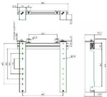
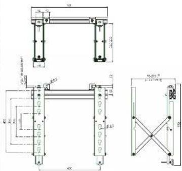
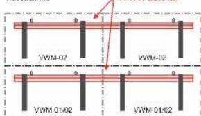
Physical Dimensions (mm)
VWM-01 VWM-02
Installation
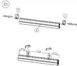
Side the well-brackets (2) with the slot nut in the slot of the aluminium profile (1). Postionate them and slightly turn on the bolts.
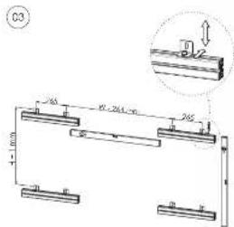
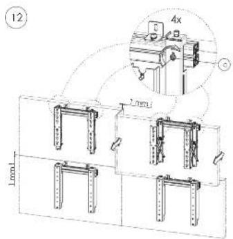
Screw now the brackets with Profile(s) on the wall. Line-up the profile(s) by adjusting the wallbrackets (2). For vertical installation check distance (H + 1 mm) and distance (W-264 mm) and make sure the profiles are leveled (In favorably as well as vertically). To save installation time we suggest to use our additional profile VWA-01.
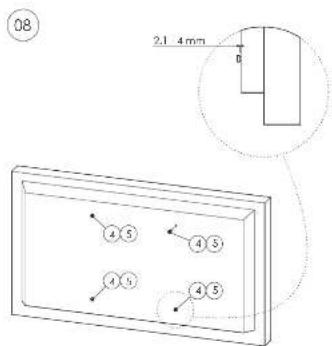
02
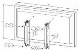
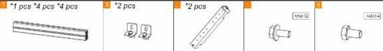
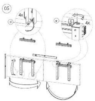
VWM-01 Mount the brackets (3) with screws (4 or 5) on the backside of the display. VWM-02 Screw only the screws (4 or 5) in the VESA holes of the display and keep a clearance of 4 mm.
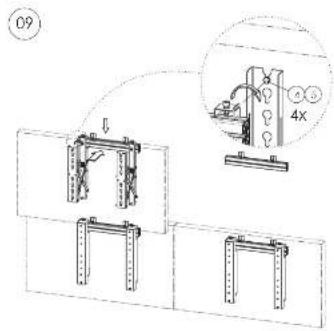
VWM-01. How the display with breakers to the aluminium profile and make sure that adjusting screw (c) does not touch the profile. VWM-02. How the module to the aluminium profile and make sure that adjusting screw (a) does not touch the profile. Place bolt (a) with associated washer in the sliding nut, but do not tighten. Place the two modules with a horizontal distance according to the width of the VESA.

neovo
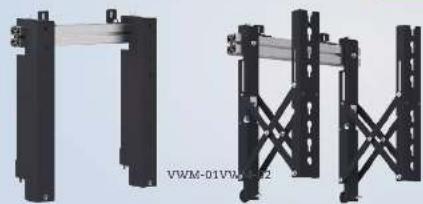
VWM-01/VWM-02/VWA-01&VWA-04
natural_image
Two black metal structural supports with diagonal braces, no visible text or symbols
Installation Manual
Video Wall Mounting Kit
VWM-01 Enclosed Parts
VWM-02 Enclosed Parts
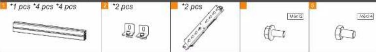
Optional Profiles VWA-01 + Brackets VWA-04
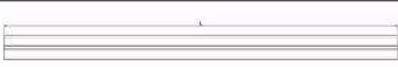
VWA-01 L=2.000 mm

VWA-04

Set-up Guide
Single use
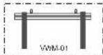
VYMM-01
Installation of single-use or in-line use
Easy installation of Videowall. Push-out function for build-in videowall, easy connecting and service of the displays.
(even lowest line can still be VWM-01)
To install displays straight in one line. For easy and fast in-line or videowall setup.
VANM-02
OPTIONAL
VWA-01
In-line use
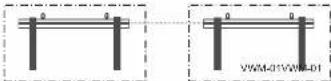
Videowall use
Installation
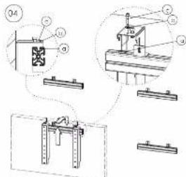
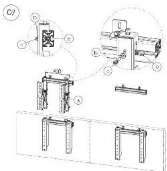
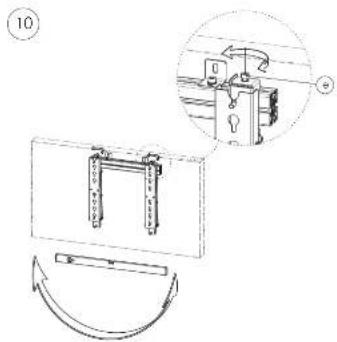
Place the screenist in the center of the aluminium profile. Adjust vertical positions by slightly turning screw (d) or balance horizontally by adjusting screw (s). If installation is perfect, fix the brackets at the profile by screw (c). For adequate installation keep a clearance of firm between the screens.
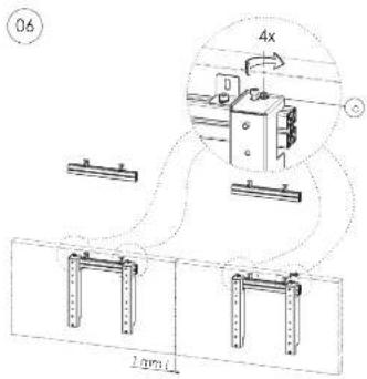
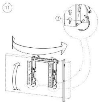
WWW-02: Hook the brackets (6) to the aluminium profile. Pass bolt (a) with associated washer in the sliding nut, fix bracket with bolt (c) into the washer through (b) but do not fightlan. Place the two brackets (6) with a horizontal distance according to the width of the VESA and push slightly on the brackets (5) so they push out. Hang the display in the open bracket (5) by gliding the screws (4) or (3) into the key holes.
VWM-02: After hanging screens(s) on pushed out brackets (6) light-up screws (4) or (5). Keep a distance of 1 mm between 2 screens. Check horizontal positions and line-funnel by turning screw (c).
Check critical position in the push open and push closed position and be aware of the 1 mm free space when opening and closing the brackets. Push the screen mounted on a VWM-02, by pressing against the included positions until a slight click is heard. The screen is now locked in the closed position. Turn screws (to) to light-up the mounts.
Hang the remaining screens by repeating the slope 4 until 10. Consider a spacing between the screens of about 1mm
Бербая золня
Press on the screen until a slight click is hoare. The screen is now uncooked and will come forward when loosening pressure. Sufficiently loosen the
screws (4) or (5) at the rear of the screen, so that the screen can be lifted out of the kidneys.
Remove the screen from the "Push to Open" modules and if needed replace it with a new screen. Tighten the rolls (from Step A) again. Push on the screen until a slight click is heard. The screen is locked in the closed position. If a display on the lowest profile needs service, then only press on the screen above until a slight click is heard. Now release hot (a) and lift slightly the lower display off the profile.
By using VWW-01 and VWW-02 in a combination, only the defect display needs to be uninstalled.