QD-10M - Stativ Libec - Gratis bruksanvisning og manual
Finn enhetens veiledning gratis QD-10M Libec i PDF-format.

Brukerspørsmål om QD-10M Libec
0 spørsmål om dette apparatet. Svar på dem du kjenner, eller still ditt eget.
Still et nytt spørsmål om dette apparatet
Last ned instruksjonene for din Stativ i PDF-format gratis! Finn veiledningen din QD-10M - Libec og ta den elektroniske enheten tilbake i hendene. På denne siden er alle dokumenter som er nødvendige for bruken av enheten din publisert. QD-10M av merket Libec.
BRUKSANVISNING QD-10M Libec
ビデオカメラ用ヘッド
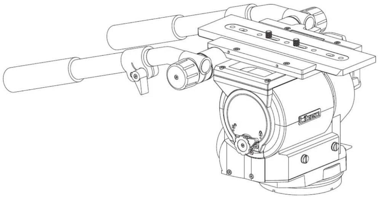
Fluid head for video camera
摄像机云台
Caveza fluid para cámara de vídeo
QH1 QH3
J 取扱説明書
E Operating manual
© 使用说明书
Es Manual de instrucciones
HEIWA SEIKI KOGYO CO.,LTD.
natural_image
Technical line drawing of a mechanical device with cylindrical components and mounting brackets (no text or symbols)J: 日本語


E: English

WARNING
If not installed and used in accordance with this manual, this equipment may cause harm.
Operating procedures and cautions were written to prevent accident from occurring.
For your own safety, read and follow these instructions before operating it. With adequate understanding, proper and safe operations will be achieved. Please retain this manual for future references. This product has been designed with consideration for your safety. However, improper operations may cause camera equipment to collapse, which may result in damage to equipment and/or cause personal injury.
Caution
Injury may happen if the guidelines are not followed.
The maximum load capacity for QH1:40kg/88.2lb, QH3:69kg/152.1lb.
Exceeding the load capacity may cause damage to equipment and/or may cause personal injury.
please activate the Center Tilt Lock for safety.
Failing to do so may cause damage to the camera or injury to others.
Mounting the camera on a improperly setup tripod may results in damages and/or personal injuries.
Dismantling and modifying the equipment may inflict injury to self or others, and may lead to defects.
Do not operate when the equipment is out of order; contact the dealer or our customer service for repair.
Precaution before use
- Please remove the camera from the tripod head. Do not carry the tripod head with the camera attached.
- Do not hold the head by the pan handle during relocation.
- When tilting or panning, it is important to loosen the tilt or pan lock completely.
- When the head is not in use for a period of time, set the counterbalance to the minimum for storage.
C: 中文

警告
Es : Español

ADVERTENCIA
Si no se instala y utiliza de acuerdo con este manual, este equipo puede causar daños.
Los procedimientos de operación y las precauciones fueron escritas para prevenir accidentes.
Por su propia seguridad, lea y siga estas instrucciones antes de operarlo. Con la comprensión adecuada, se lograrán operaciones adecuadas y seguras. Conserve este manual para futuras referencias. Este producto ha sido diseñado teniendo en cuenta su seguridad. Sin embargo, las operaciones incorrectas pueden provocar el colapso del equipo de la cámara, lo que puede provocar daños en el equipo y / o lesiones personales.
Precaución
Este equipo puede causar lesiones si no se instala o usa de la manera en que se especifican en las instrucciones.
La capacidad de carga máxima de QH1: 40kg / 88.2lb, QH3: 69kg / 152.1lb.
Superar la capacidad de carga puede causar daños al equipo y / o lesiones personales.
inclinación central para mayor seguridad.
Si no lo hace puede causar daños a la cámara y / o lesiones a otras personas.
Montar la cámara en un trípode mal instalado puede causar daños y / o lesiones personales.
El desmontaje y la modificación del equipo pueden causar lesiones a sí mismos oa otros, y pueden provocar defectos.
No operar cuando el equipo está fuera de servicio; Póngase en contacto con el distribuidor o con nuestro servicio de atención al cliente para su reparación.
Precauciones antes de su uso
- Retire la cámara de la cabeza del trípode. No lleve la cabeza del trípode con la cámara instalada.
- No sujete el cabezal por el maneral durante el traslado.
- Cuando se inclina o se desplaza, es importante aflojar completamente el seguro de la inclinación o paneo.
- Cuando la cabeza no esté en uso por un período de tiempo, ajuste el contrapeso al mínimo para el almacenamiento.
A


A:
L R
3/8-16 UNC
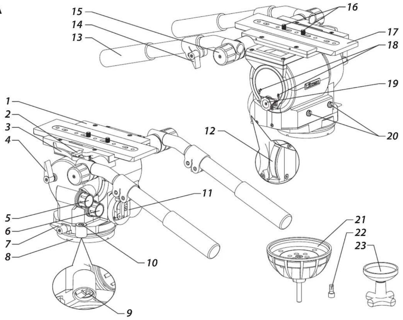
A: Part name A:
1 Ilead 1
2 Slide plate safety release lock 2
3 Quick release mechanism 3
4 Tilt lock 4
5 Tilt drag control 5
6 Pan drag control 6
7 Pan lock 7
8 Flat base 8
9 Level illumination switch 9
10 Bubble level 10
11 Counterbalance knob 11
12 Counterbalance meter 12
13 Pan handle (L, R) 13
14 Telescopic clamp 14
15 Pan handle clamp 15
16 Camera screw 16
17 Slide plate 17
18 Center Tilt Lock Icons 18
19 Center Tilt Lock 19
20 Spare camera screw 20
Screw hole (3/8-16 UNC)
21 Ball leveler 21
22 Ball leveler fixing screw 3/8" 22
23 Bowl clamp 23
A: Nombre de la pieza
1 Cabeza
2 Cierre de seguridad para placa deslizante
3 Mecanismo de liberación rápida
4 Seguro de inclinación
5 Control de arrastre de inclinación
6 Control de arrastre de paneo
7 Seguro de paneo
8 Base plana
9 Interruptor de iluminación de nivel
10 Nibel de burbujas
11 Perilla del seguro de contorapeso
12 Medido de contrabalance
13 Abrazadera de deslizamiento (L, R)
14 Sujetadoe de la extension
15 Abrazadera de maneral
16 Perilla del seguro de la placa
17 Placa deslizante
18 Iconos de seguro de inclinación central
19 Seguro de inclinación central
20 Tornillo de repuesto de la cámara
Orificio de tornillo (3 / 8-16 UNC)
21 Nivelador de bola
22 Tornillo de fijación 3/8 para nivelador de bola
23 Manija de fijación de nivelador de bola
B:
1
2
3
4
5
6
7
8
9
10
11
12
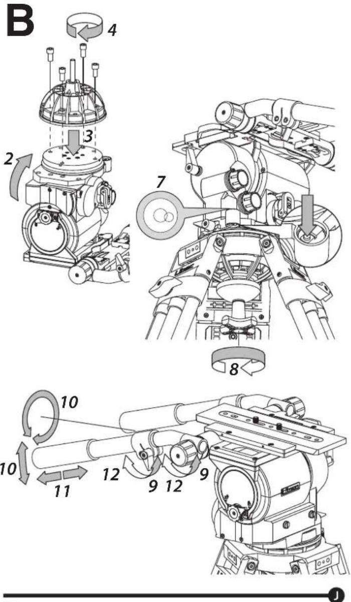
B: Placing the tripod head.
Attaching a flat-base head
1 Secure the head with 4x 3/8" screws.
P1000.
Changing the flat-base configuration to a ball-base configuration
2 Remove the slide plate and place the head with the flat-base facing up.
3 Place the ball leveler on top of the flat base and match each hole.
4 Use the hexagon wrench to firmly attach the 4x 3/8" screws.
during usage.
Mounting the ball-base configuration head
5 Loosen the bowl clamp and remove it from the head.
6 Set the head on to the tripod.
Leveling the head
7 Hold the head, look at the bubble level and glide the ball leveler while keeping the bubble at the center.
about 10 to 15 sec. LED will cut off after this period or by pressing the switch again.
8 Firmly tighten the bowl clamp.
Adjusting the pan handle to the preferred length
9 Loosen the telescopic clamp.
10 Adjust the position.
11 Adjust the length.
12 Lock the telescopic clamp.
B:
1
2
3
4
5
6
7
8
9
10
11
12
B: Colocando la cabeza del trípode.
Colocando una cabeza de base plana
1 Asegure la cabeza con 4x 3/8" tornillos.
Consulte el manual de funcionamiento de P1000 cuando coloque la cabeza en el P1000.
Cambio de la configuración de base plana a una configuración de
base de bola
2 Retire la placa deslizante y coloque la cabeza con la base plana hacia arriba.
3 Coloque el nivelador de bola encima de la base plana y haga coincidir cada orificio.
4 Use la llave hexagonal para sujetar firmemente los tornillos de 4x 3/8. Asegúrese de que los tornillos estén bien apretados o podrian aflojarse durante el uso.
Montaje del cabezal de configuración de base de bola
5 Desajustar la abrazadera de fijación de niveladora de bolas y retirarla.
6 Colocar la cabeza en el trípode.
Ajuste el nivel de la cabeza
7 Sostenga la cabeza, mire el nivel de la burbuja y deslice el nivelador de la bola mientras mantiene la burbuja en el centro.
Apriete el interruptor de iluminación y el nivel de burbuja se iluminará aproximadamente de 10 a 15 segundos, la luz se cortará después de este período o apretando el interruptor otra vez.
8 Ajuste la abrazadera de fijación del nivelador de bola firmemente.
Ajuste el maneral a la longitud preferida
9 Afloje la abrazadera telescópica
10 Ajustar la posición
11 Ajustar la longitud
12 Asegura la abrazadera telescópica
Colocar la cabeza en el trípode.
C:
1 2 3
4 5 6
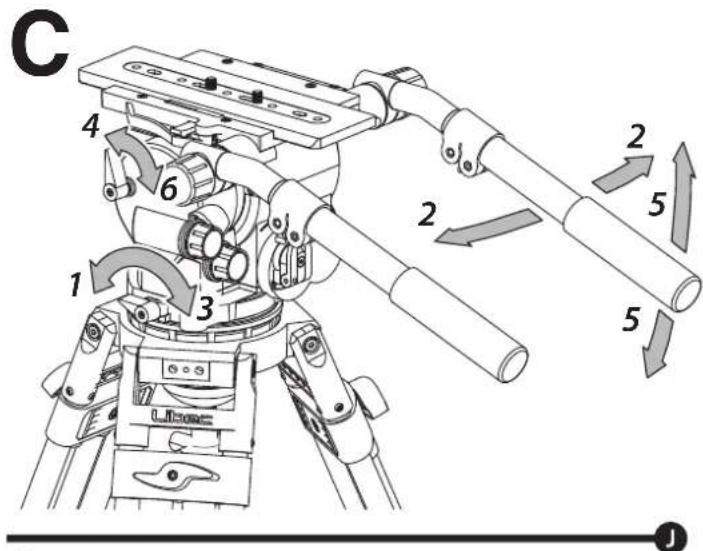
C: Panning and Tilting
Pannig
1,2 Release the pan lock for left and right movement.
3 Firmly tighten the pan lock, if locking is necessary.
Tilting
4,5 Relase the tilt lock for up and down movement. 6 Firmly tighten the tilt lock, if locking is necessary.
C:
1 2 3
4 5 6
C: Deslizamiento e inclinación
Deslizamiento
1,2 Libere la perilla del seguro de deslizamiento para el movimiento de
3 izquierda a derecha.
Si es necesario, ajuste la perilla del seguro firmemente.
Inclinación
4,5 Libere la perilla del seguro de inclinación para el movimiento de arriba hacia abajo.
6 Si es necesario, ajuste la perilla del seguro firmemente.
D:
1 2 3 4
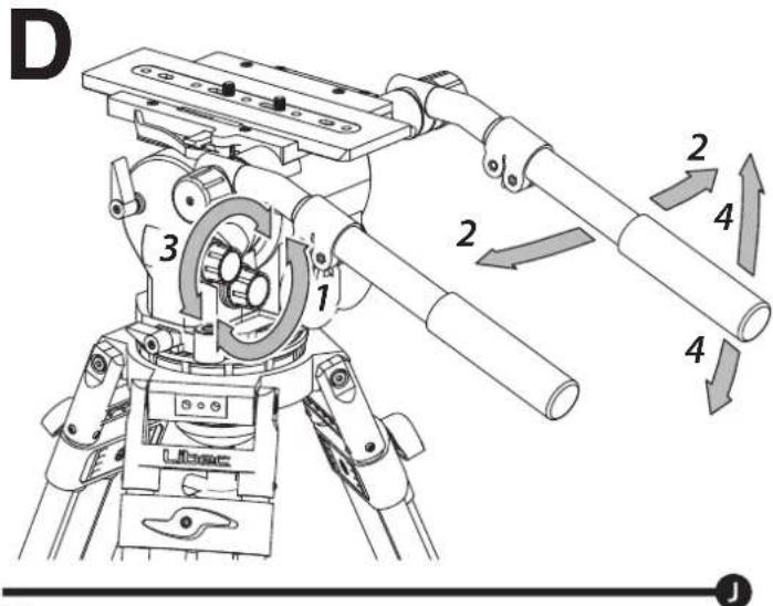
D: Change torque for panning and tilting
You can choose from 7 different levels of torque for panning and tilting. Choose the level of torque depending on the type of filming to be done.
Change torque for panning
1 Use the pan torque knob to select desired level of torque.
2 Pan the camera to check the level of torque is correct.
Change torque for tilting
3 Use the tilt torque knob to select desired level of torque.
4 Tilt the camera to check that the amount of torque is correct.
D:
1 2 3 4
D: Cambiar el torque para deslizamiento e inclinación
Puede elegir entre 7 niveles diferentes de torque para deslizamiento e inclinación. Elija el nivel de torque según el tipo de filmación a realizar.
Cambiar el torque para deslizamiento
1 Use la perilla del seguro de deslizamiento para seleccionar el nivel de torque deseado.
2 Deslice la cámara para controlar que el nivel de torque sea correcto.
Cambiar el torque para inclinación
3 Use el seguro de inclinación para seleccionar el nivel de torque deseado.
4 Incline la cámara para controlar que la cantidad de torque sea la correcta.
E
natural_image
Technical line drawing of a mechanical assembly with no visible text or symbolsE:

3/8"

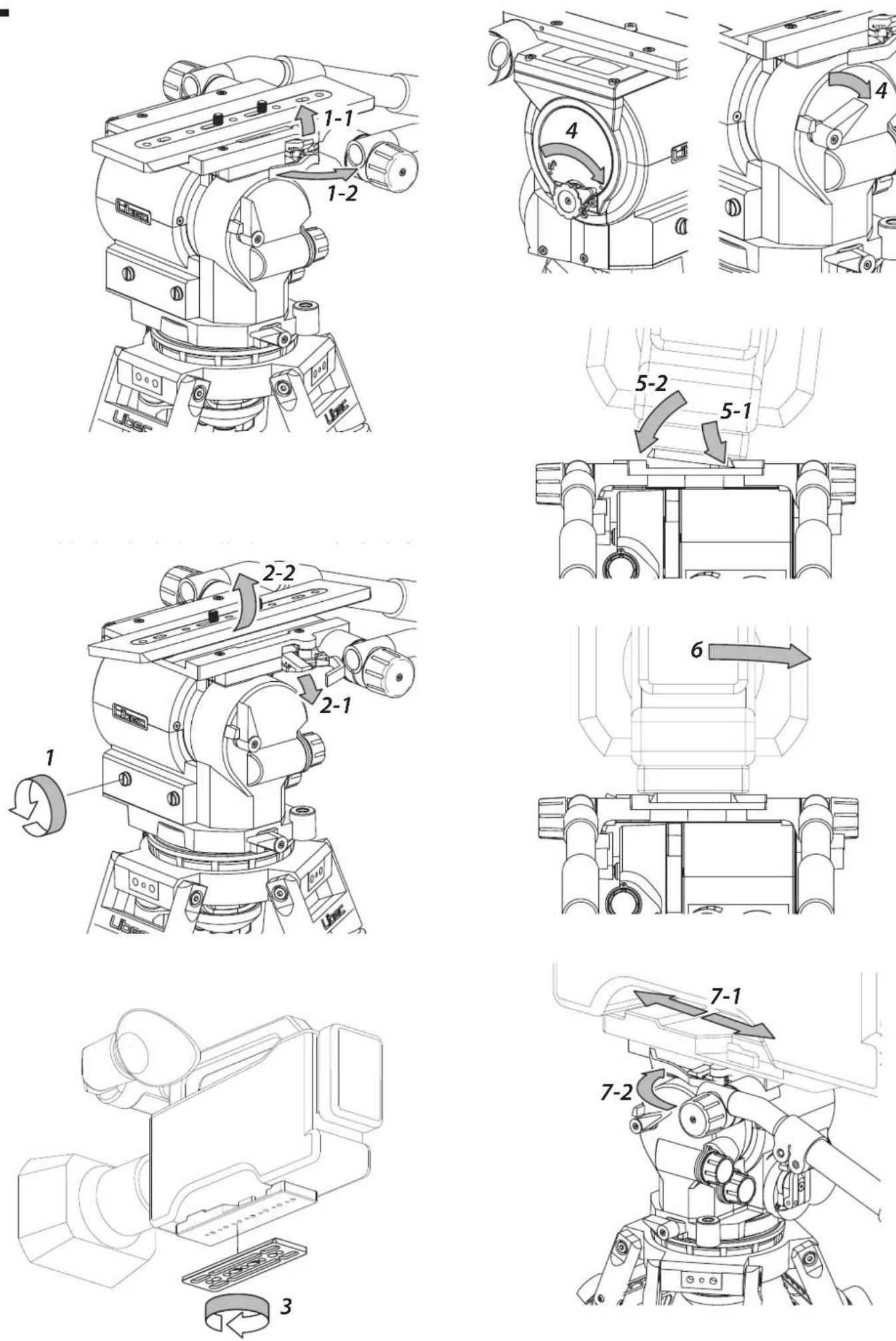
E: Mounting of the camera

please set the head with the following instructions.
strength to more than 50% in the counterbalance range
Removing the slide plate
1 Pull the quick release mechanism (1-2) and pull up the slide plate safety release lock (1-1) to unlock the slide plate.
2 Push down on the slide plate safety release lock (2-1) and remove the slide plate (2-2).
Attaching the slide plate
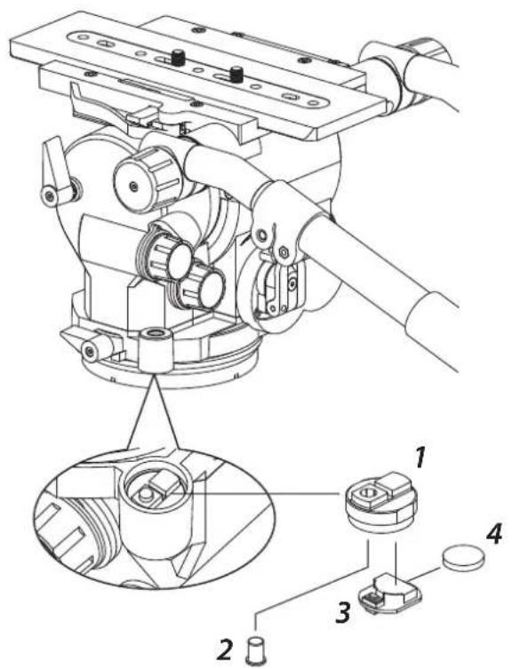
3 Set and tighten the camera screw of the slide plate to the camera adapter plate.
Use these screws for additional reinforcement.
Attaching the camera to the head
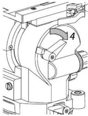
4 Activate the center tilt lock and secure the tilt lock knob.
5 Put the right side of the slide plate into the right side of the slide gap (5-1), and push down the left side of the slide plate until hearing a "click" sound (5-2).
6 After attaching the camera, hold the camera and check if the slide plate is securely on the head.
7 Slide the slide plate to a preferred position (7-1), and use the quick release mechanism to lock the slide plate firmly (7-2).
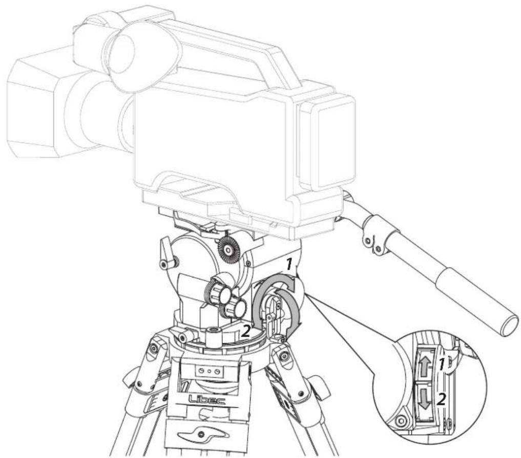
Activating and deactivating the center tilt lock
Activate
Deactivate


E:

1
2
3
4
5
6
7
1
2
3
4
5
6
7
1
2
3
4
5
6
7
1
2
3
4
5
6
7
1
2
3
4
5
6
7
1
2
3
4
5
6
7
1
2
3
4
5
6
7
1
2
3
4
5
6
7
1
2
3
4
5
6
7
1
2
3
4
5
6
7
1
2
3
4
5
6
7
1
2
3
4
5
6
7
1
2
3
4
5
6
7

F
F:
J
F:
1
(1-1)
1
2
2
E
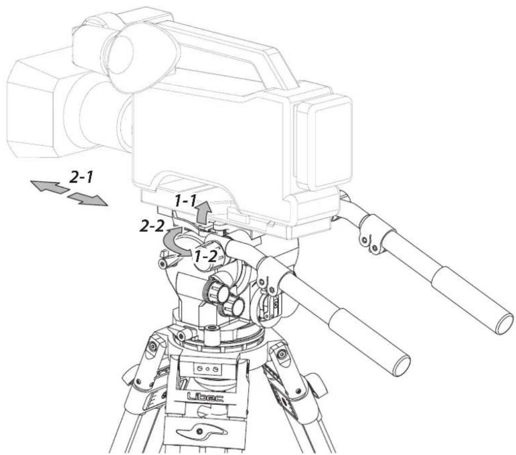
F: Adjust the front-back balance
Adjust the front-back balance of the camera by adjusting the slide plate's position.
tilt and may cause damage to equipment and/or lead to personal injury.
1 While supporting the camera, pull up the slide plate release lever (1-1) and pull the quick release mechanism (1-2) to unlock the slide plate.
2 While supporting the camera, slide the camera with the slide plate to the front or back direction (2-1), and lock the slide plate when the camera is at a balanced position (2-2).
F: Ajustar el balance delantero-trasero
Ajuste el balance delantero-trasero de la cámara ajustando la posición de la placa deslizante.
inclinación central.
inclinarse y causar daños al equipo y / o provocar lesiones personales.
1 Mientras sostiene la cámara, levante la palanca de liberación de la placa deslizante (1-1) y tire del mecanismo de liberación rápida (1-2) para retirar la placa deslizante.
2 Mientras sostiene la cámara, deslice la cámara con la placa deslizante hacia la dirección frontal o posterior (2-1), y segure la placa deslizante cuando la cámara esté en una posición equilibrada (2-2).
G
G:

1 2
G:

1 2
G: Adjusting the counterbalance
The counterbalance mechanism uses an inner spring to maintain the loaded camera to any still position no matter the direction or angle selected. Counterbalance tension can be adjusted by the counterbalance knob. Turning it clockwise increases the tension, counter clock-wise decreases the tension. Select the tension suitable for your needs.
1 Increase 2 Decrease
The position of the pointer: Up (Strong) > Down (Weak)
position and lock the center tilt lock. Keep holding the camera and check the front-back balance while adjusting the counterbalance.
G: Ajuste de contrapeso
El mecanismo de contrapeso usa un resorte interno para mantener la cámara en la posición central sin importar la dirección o ángulo seleccionado. La tensión del contrapeso puede ajustarse mediante el seguro de contrapeso. Al moverlo en el sentido de las agujas del reloj aumenta la tensión. Al moverlo en el sentido contrario a las agujas del reloj disminuye la tensión. Seleccione la tensión adecuada para sus necesidades.
1 Subir 2 Bajar
La posición del puntero: Arriba (Fuerte)> Abajo (Débil)
horizontal y segure el seguro de inclinación central. Siga sosteniendo la cámara y verifique el equilibrio de la parte delantera y trasera mientras ajusta el contrapeso.
H
H-1
H-2
5
natural_image
Technical line drawing of a mechanical device with gears and housing (no text or symbols)6
natural_image
Mechanical component diagram showing a curved housing with a downward arrow and a separate plate (no text or symbols)7
8
9
natural_image
Diagram of a mechanical component with two arrows indicating direction, no text or symbols present10
natural_image
Diagram showing a mechanical component before and after transformation, with no visible text or symbols.11
natural_image
Technical line drawing of a mechanical device with gears and housing (no text or symbols)H:
H-1
7
2
3
4
H-2
5
6
7
8
9
10
11

H:
H-1
1
2
3
4
H-2
5
6
7
8
9
10
11

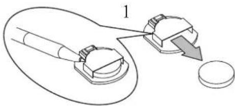
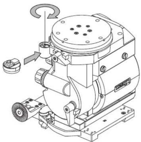
H: Level illumination
H-1 Parts of level illumination
1 Level illumination holder
2 Level illumination switch
3 PCB unit
4 Battery
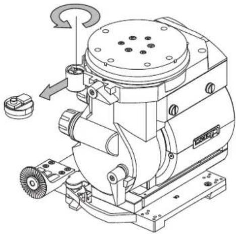
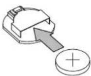
H-2 How to replace the battery (Using battery : CR1220)
5
Loosen and remove the level illumination holder.
6 Remove the PCB unit from the level illumination holder.
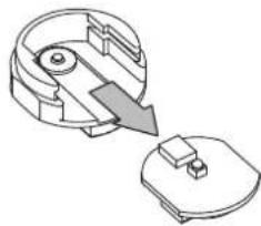
7 Turn over the PCB unit and remove the battery.
of the opening.
8 New battery with positive face up and insert into the opening.
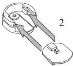
9 Insert PCB unit into level illumination holder with the battery side face down.
holder and slide to the end.
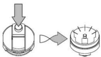
10 Functional check by pressing the level illumination switch.
11 Ensure to tighten the level illumination holder.
H: Nibel de iluminación
H-1 Partes de nivel de iluminación
1 Sosten de nivel de iluminación
2 Interruptor de nivel de iluminación
3 Unidad PCB
4 Batería
H-2 Cómo reemplazar la batería (Batería a usar : CR1220)
5
Afloje y quite al sosten de nivel de iluminación.
6 Quite la unidad de PCB del sosten del nivel de iluminación.
7 Voltie la unidad de PCB y remueva la batería.
opuesto de la apertura.
8 Cuando remplace la bateria asegurece de que el lado + positivo esta hacia
9 Inserte la unidad PCB en el sotenedor de nivel de iluminación con la batería viendo hacia abajo.
de iluminacion y deslisarlo hasta el fondo.
10 Verifique el funcionamineto Apretando el interruptor del nivel de iluminación.
11 Asegure de apretar el sosten del nivel de iluminación.
平和精機工業株式会社
TEL.048-995-1301(代)
HEIWA SEIKI KOGYO CO.,LTD. - Headquarters
TEL:+81(0)48 995 1301
Libec Sales of America, Inc - U.S. Sales office
TEL:+1 310 787 9400
Libec Asia Pacific Pte. Ltd. - Singapore office
TEL:+65 6296 9930