Synchrodyne - Synthesizer WMD - Gratis bruksanvisning og manual
Finn enhetens veiledning gratis Synchrodyne WMD i PDF-format.

Brukerspørsmål om Synchrodyne WMD
0 spørsmål om dette apparatet. Svar på dem du kjenner, eller still ditt eget.
Still et nytt spørsmål om dette apparatet
Last ned instruksjonene for din Synthesizer i PDF-format gratis! Finn veiledningen din Synchrodyne - WMD og ta den elektroniske enheten tilbake i hendene. På denne siden er alle dokumenter som er nødvendige for bruken av enheten din publisert. Synchrodyne av merket WMD.
BRUKSANVISNING Synchrodyne WMD

Denver, CO http://wmdevices.com 303-549-9205 sales@wmdevices.com
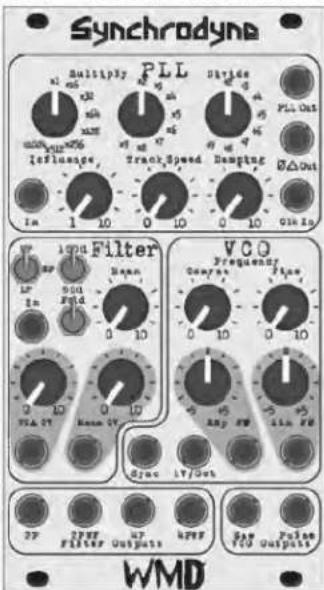
Thank you for purchasing the WMD Synchrodyne. We hope you enjoy its sound and features. The Synchrodyne is a multitude of modules put together to create a flexible and stable Switched Capacitor filter. It consists of three main parts.
vco
The Synchrodyne's VCO is a traditional Sawtooth Core. Its frequency range is .02Hz to 400kHz .
1V/Oct Input - Calibrated input for pitch control. The VCO will track at least 5 octaves using this input.
Sync Input - Rising edge sawtooth reset/sync input. Does not affect slope of sawtooth.
Coarse & Fine Knobs - Coarse knob adjust the frequency of the VCO throughout its full range. Use the Fine knob to tune the oscillator within approximately 1/3 octave range.
Exp FM - This input jack and bipolar attenuator provide exponential FM to the VCO. This input is DC coupled.
Lin FM - This input jack and bipolar attenuator provide linear FM to the VCO. This input can be DC or AC coupled. A jumper on the back enables DC coupling when in place. We recommend AC coupling to prevent frequency shift caused by the bipolar attenuator's offset voltage.
Saw Output - The Sawtooth output is available here. Its level is approximately +-4.5 volts.
Pulse Output - This output presents the rectangle wave necessary for driving the PLL. It is not a 50% duty cycle square, but approximately 30%/70% as that provided the best performance for driving PLL.
Phase Locked Loop (PLL)
The PLL takes the rectangle wave from the VCO and drives the filter.
CLK Input - The Pulse Output from the VCO is normaled here. Plug in an external clock source to drive the PLL with something else.
Multiply & Divide Switch Knobs - These rotary switches adjust the frequency of the clock multiplier & divider inside the PLL. Adjust these to set the frequency ratio. Higher multiplication factors cause the PLL to react slower to changes, especially at low input frequencies. Phase Delta Output - This output represented by symbols is the result of the multiplication factor. It produces some self PWM as the PLL stabilizes and will equal the input clock frequency if the PLL is locked. This output provides an interesting self modulating audio or clock source.
PLL Output - This is the output of the PLL stage. It is the input frequency multiplied and divided by the set ratios.
Track Speed Knob - This controls the reaction speed of the PLL in trying to keep up with changes to the input frequency. Fully CCW it will introduce lots of glissando in the filter reaction. Fully CW and it will over-track, causing the PLL to respond faster than the input frequency. Overtracking produces bursts of high frequency output and low frequency output.
Damping Knob - This control reduces the rate of fluctuation while overtracking, damping the overtracking and increasing stability. More damping will be needed as higher ratios of Frequency Multiplication are selected.
Influence Input and Knob - This control acts directly with the Track Speed and Damping controls in stabilizing the frequency of the PLL. Use a voltage source to modulate the PLL signal. Very complex modulations are possible by using Influence with the internal VCO and other controls.
Synchrodyne
Filter
The core of the Synchrodyne is a 4 pole (-24dB/octave) Switched Capacitor Filter circuit. The 2 pole output is tapped and provides a mellower filter sound. The Synchrodyne will self-oscillate at high resonances on both outputs, however it is more prominent on the 4 Pole output.
The Switched Capacitor Filter topology has a few interesting features. It is a sampled data construct, so at low cutoff frequencies, the filter will produce aliasing noise, similar to the sample rate reduction on the Geiger Counter. This topology is also very stable and accurate, allowing for predictable cutoff frequencies to be selected. Across its entire range (.02 Hz to 16kHz) the filter will remain within +-0.2% of where it should be.
In Jack - Insert signal to be filtered here.
VCA CV Input and Knob - When there is no input to the VCA CV jack, the knob acts as an attenuator for the input signal. Plugging into the VCA CV jack causes the knob to act as an attenuator for the CV signal controlling the input VCA.
Fold Toggle - Flipping this up causes the input VCA to drive a four stage wavefolder. The output of the wavefolder then goes o the filter. The level of the input signal going into the filter from the wave-folder is adjustable with the blue trim-pot on the back of the Synchrodyne. This will be broken out to the expansion. Resonance Knob - Directly Controls the resonance of the Switched Capacitor Filter.
Resonance CV Input and Attenuator - This input will add to the primary Resonance knob through the attenuator. Use for animating the Filter's resonance.
100:1 - 50:1 Ratio Toggle - This controls the filter core's frequency ratio. There is one octave of difference between the two settings. At low frequencies, the 50:1 ratio will produce more aliasing/sampling distortion.
LowPass / BandPass / HighPass Toggle - Selects the output mode of both the 2 Pole and 4 Pole outputs.
Filter Outputs - Jacks for the 2 Pole (-12dB/oct) and 4 Pole (-24dB/oct) are available. Please note that they are 180 degrees out of phase from each other. Additionally, a single stage wave-folded output is available for both the 2 Pole and 4 Pole outputs. The wave-folded outputs provide another level of sonic depth to experiment with.
Warranty and Other Information
The Synchrodyne is 14 HP.
Current consumption is 60mA for the +12 rail; 50mA for the -12 rail.
The majority of the audio circuitry runs at +-5 volts and uses high-speed rail to rail opamps.
The depth from the back of the panel is roughly 40mm with connectors.
They Synchrodyne is reverse polarity protected.
The Synchrodyne is RoHS and CE compliant.
The Synchrodyne is warranted for 12 months after purchase. But please contact us if you ever have problems. We will take care of you.
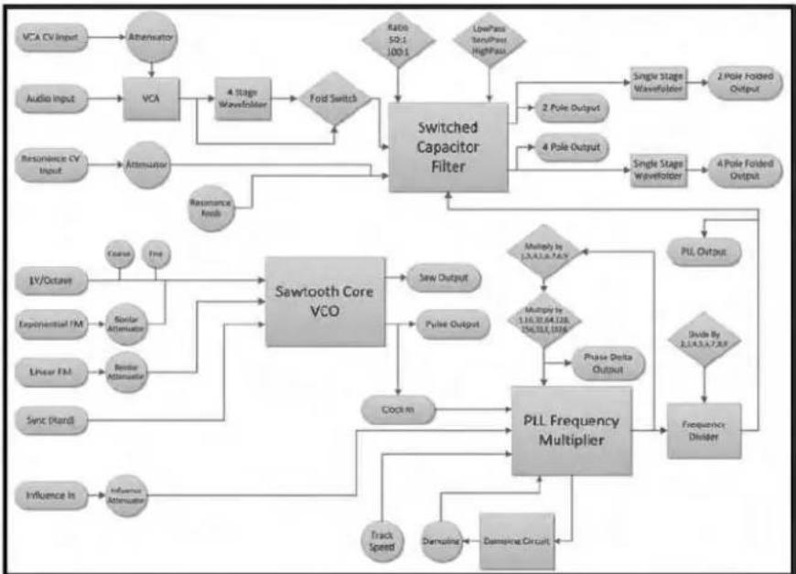
flowchart
graph TD
    A["VCA CV Input"] --> B["Attenuator"]
    C["Audio Input"] --> D["VCA"]
    D --> E["4 Stage Wavelet"]
    E --> F{Fod Switch}
    F --> G["Switched Capacitor Filter"]
    H["Resonance CV Input"] --> I["Attenuator"]
    I --> J["Resonance Reels"]
    J --> G
    K["I/V/Octave"] --> L["Sawtooth Core VCO"]
    M["Exponential TM"] --> L
    N["Linear FM"] --> O["Bearb Attenuator"]
    P["ServX (Hard)"] --> Q["Influence In"]
    R["Influence In"] --> S["Influence Attenuator"]
    L --> T["Saw Output"]
    U["Swiss"] --> V["Pulse Output"]
    W["Clock In"] --> X["PLL Frequency Multiplier"]
    Y["Track Speed"] --> X
    Z["Damping"] --> AA["Demagonal Circuit"]
    AB["Multiplied to 1.3.4.5.6.7.8.9"] --> AC["Multiple in 1.16.10.64.128, 106.011.0706"]
    AD["Phase Delta Output"] --> X
    AE["Frequency Divider"] --> X
    AF["Single Stage Wavelet"] --> AG["2 Pole Output"]
    AH["Single Stage Wavelet"] --> AI["2 Pole Folded Output"]
    AJ["2 Pole Folded Output"] --> AK["4 Pole Output"]
    AL["Rate 50:1, 100:1"] --> G
    AM["Lowpass Spread High Pass"] --> G
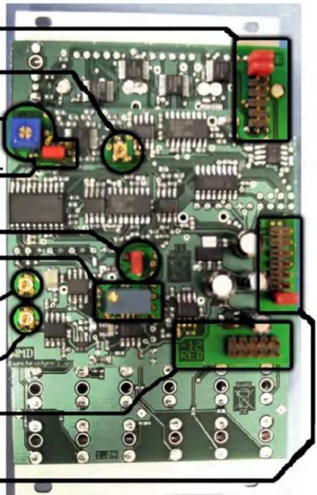
The Synchrodyne is calibrated at the factory and calibration should not be necessary.
PLL Expansion Header Top two sets of pins must be jumpered if expansion is not connected.
Wavefolder Bias trim.*
Wave Folder Level Trim
Jumper if no Audio expansion.
Linear FM AC/DC Jumper Connect Pins for DC FM
1V/Octave Trim*
Sawtooth Offset. Set so that saw wave is centered about 0V.*
PWM Trim. Set so that at maximum VCO frequency, Pulse Output level is centered about 0V.*
Power Header, Red Stripe to the Left.
Audio Expansion Header Bottom set of pins must be jumpered if expansion is not connected.
For connecting expansions, remove jumpers and connect red stripe of 14 pin cable towards the asterisk (*).
* indicates factory calibrated.