SSP10 - Videokamera Autocue QTV - Gratis bruksanvisning og manual
Finn enhetens veiledning gratis SSP10 Autocue QTV i PDF-format.

Brukerspørsmål om SSP10 Autocue QTV
0 spørsmål om dette apparatet. Svar på dem du kjenner, eller still ditt eget.
Still et nytt spørsmål om dette apparatet
Last ned instruksjonene for din Videokamera i PDF-format gratis! Finn veiledningen din SSP10 - Autocue QTV og ta den elektroniske enheten tilbake i hendene. På denne siden er alle dokumenter som er nødvendige for bruken av enheten din publisert. SSP10 av merket Autocue QTV.
BRUKSANVISNING SSP10 Autocue QTV
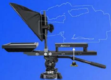
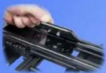
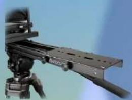
Camera Fixing
natural_image
Technical diagram of a medical or optical instrument with labeled components and a blue background (no readable text or symbols)It is important that the camera lens is in the centre of the aperture at the rear of the hood. This is achieved by raising and lowering the camera mounting plate and hood.

1/4" BSW
Fix the camera in place using the camera screw provided.
Camera Screw
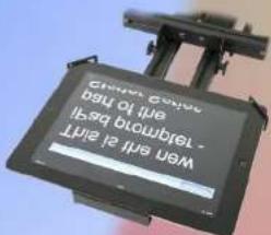
Monitor
Connect the power supply and the VGA or video cable.
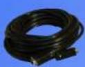
VGA Cable
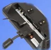
natural_image
Close-up of a black electronic device with internal components and a cable (no visible text or symbols)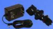
Power Supply
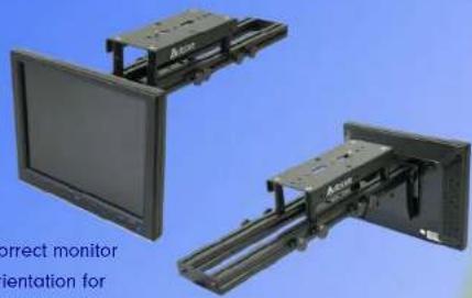
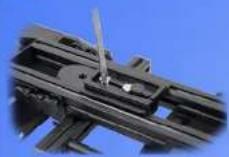
Alternative Configuration
The SSP 10" monitor can be reconfigured to straight read mode. To achieve this remove the hood unit by loosening the two thumb screws of the monitor mount and move the monitor to the vertical position. Remove the monitor from the bracket by removing the 4 screws and refit the monitor in the correct orientation.
natural_image
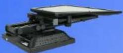
Two mechanical assembly units with mounted brackets against a blue background (no text or symbols visible)iPad Adaptor
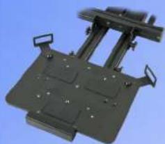
natural_image
Mechanical device with mounting brackets and a central support frame (no visible text or symbols)iPad adaptor
By replacing the 10" display with the iPad adaptor it is possible to mount an iPad 1 or 2 and use this as the prompting display.

autocue.com
SSP10
Guide


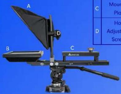
Components
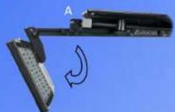
| A | Hood and Glass |
| B | Monitor |
| C | Mounting Plate |
| D | Hood Adjustment Screws |
- Fix the hot shoe from your tripod to the underside of the mounting plate. Slide the hot shoe to the approximate position and tighten the screws.
- Mount the unit on the tripod and raise the hood to the upright position
Assembly
- Loosen the thumb screws (A) and move the monitor into the horizontal position.
Re-tighten the monitor thumb screws.
natural_image
Close-up of a mechanical device with a curved arrow indicating rotation or motion (no visible text or symbols)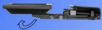
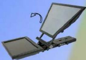
- Move the hood up and lock into position by tightening the four thumb screws (B)
natural_image
Illustration of a flat-screen computer monitor with an open tray and a curved arrow indicating rotation (no text or symbols)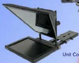
natural_image
Illustration of a flat-screen monitor with a screen, mounted on a stand (no text or symbols visible)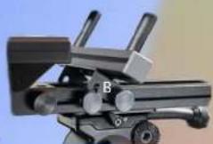
Hood Lock
Unit Complete
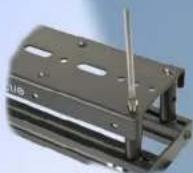
Mounting the Camera
- For larger cameras the mounting plate may need extending. Loosen the four thumb screws on the camera plate and remove the rear two, the plate will now slide out. Replace the two rear screws and tighten them to secure the plate.
natural_image
Close-up of a mounted optical or mechanical device with a black frame and tripod base (no visible text or symbols)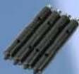
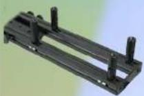
Pillar Kit
- For smaller cameras the camera plate will need to be raised. Remove the four thumb screws and lift off the plate.
-
Install four camera plate pillars of the appropriate height.
-
Re-fix the camera plate using the four screws provided.

To achieve the maximum height, combine two pillars.
Pillar combinations
Autocue