CS-CPS-20A - Stativ Axler - Gratis bruksanvisning og manual
Finn enhetens veiledning gratis CS-CPS-20A Axler i PDF-format.

Brukerspørsmål om CS-CPS-20A Axler
0 spørsmål om dette apparatet. Svar på dem du kjenner, eller still ditt eget.
Still et nytt spørsmål om dette apparatet
Last ned instruksjonene for din Stativ i PDF-format gratis! Finn veiledningen din CS-CPS-20A - Axler og ta den elektroniske enheten tilbake i hendene. På denne siden er alle dokumenter som er nødvendige for bruken av enheten din publisert. CS-CPS-20A av merket Axler.
BRUKSANVISNING CS-CPS-20A Axler

AXLER™

natural_image
Technical line drawing of a mechanical device with vertical rods and central circular component (no text or symbols)CS-CPS-20a
QUICK-START
GUIDE
PRECAUTIONS
- Please read and follow these instructions, and keep this manual in a safe place.
- Keep this product away from children.
- Make sure everything is secure before proceeding.
- Make sure that this product is intact and that there are no missing parts.
- To avoid damage to this product, be careful not to overtighten or improperly thread any of the threaded fittings.
- Do not exceed the maximum load capacity.
- Be careful not to catch your fingers in any of the moving parts.
- All images are for illustrative purposes only.
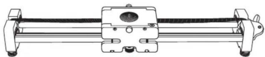
OVERVIEW
Slider:
- Camera base
- Mounting plate locks
- Top mounting plate
- Belt
- Brake
- Adjustable feet (×4)
- Tripod mounting sockets * (1/4"-20 and 3/8"-16) *under mounting base
- Mounting base
- Bubble level
Also Included:
• 3/8"-16 bushing (for camera mount)
- 7/64" hex key
(for tension screw adjustment)
- T9 hex key
- Set screws (×2)
- Carry case
- User manual

GETTING STARTED
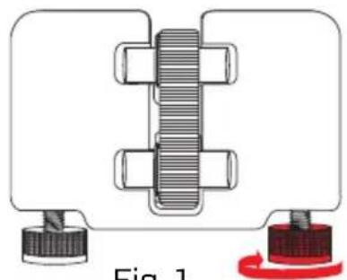
Place the CS-CPS-20a Expanding Caterpillar Slider on a steady surface. When used on its feet, e.g., on the ground or a table, the CS-CPS-20a offers 18" of sliding. You can adjust the length of the feet to prevent the slider from wobbling and fine-tune the position of the slider.
To extend the foot, rotate it clockwise. To retract the foot, rotate it counterclockwise. (Fig. 1)
Tip: Use the onboard bubble level to determine whether your shot is aligned with the horizon.
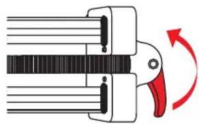
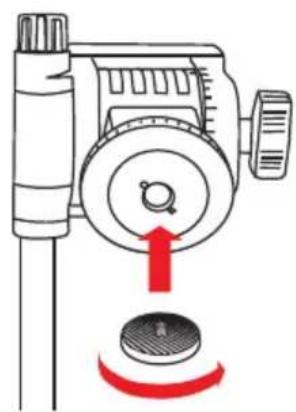
MOUNTING THE SLIDER
You can use a heavy-duty tripod or light stand to support the slider and gain both height and tracking length. When mounted, the CS-CPS-20a delivers 30" of sliding length. The slider's mounting base is equipped with 1/4"-20 and 3/8"-16 sockets.
To mount the slider, follow these steps:
-
Center the mounting base on the slider, and lock it down by tightening the brake. (Fig. 2)
-
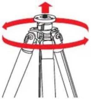
Align your tripod's threaded post with the corresponding mounting socket in the slider's mounting base. Place the slider onto the threaded post and carefully rotate the tripod until fully attached. (Fig. 3)
-
Mount your camera to the slider according to the directions below.
Note: To avoid wobbling and camera shake, use sand bags or other weights to stabilize your tripod.
natural_image
Mechanical assembly diagram showing a bolted joint with threaded shaft and two end caps (no text or symbols)Fig. 1
natural_image
Diagram of a mechanical clamp or clamping device with a red-handled arrow indicating rotational motion (no text or symbols present)Fig. 2
natural_image
Technical line drawing of a mechanical assembly with no visible text or symbolsFig. 3
natural_image
Diagram of a tripod-mounted surveying instrument with red circular motion arrows indicating rotational direction (no text or symbols)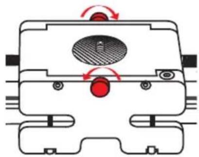
natural_image
Technical diagram of a mechanical component with directional arrows indicating motion or force (no text or symbols)Fig. 4 Fig. 5
natural_image
Diagram of a mechanical device with a red arrow indicating rotation or adjustment, no text or symbols present.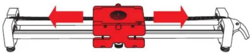
natural_image
Mechanical assembly diagram showing a red component mounted on a rail with directional arrows indicating motion (no text or symbols)MOUNTING YOUR CAMERA/TRIPOD HEAD TO THE SLIDER
Important!
Before mounting your camera, lock down the camera base by tightening the brake.
The camera base's 1/4"-20 mount comes with the included 3/8"-16 bushing preinstalled. If your tripod head has a 1/4"-20 socket, remove the 3/8"-16 bushing from the mount before attaching your tripod head.
To mount a camera or tripod head, follow these steps:
- Loosen the mounting plate locks and remove the top mounting plate from the camera base. (Fig. 4)
- Align the mounting post with the mounting socket of your camera or tripod head, and screw the top mounting plate in. (Fig. 5) Use a Phillips screwdriver to fully tighten.
- Place the assembly onto the camera base, and tighten the mounting plate locks until secure.
Note: For heads that are wider than the mounting plate, use the included set screws and T9 hex keyto tighten the mounting plate to the slider.
USING THE SLIDER
Once your camera is mounted, loosen the brake and use your tripod head's pan handle to move your camera along the slider. If the slider is positioned at an incline, keep one hand on the camera base before loosening the brake.
SPECIFICATIONS
- Slide length: Unmounted: 18" (45.7 cm)
Mounted: 30" (76.2 cm) - Max load capacity: 12 lb. (5.4 kg)
- Mount size: Camera: 1/4"-20
(3/8"-16 bushing included)
Tripod: 1/4"-20 and 3/8"-16 - Drive type: Belt
- Dimensions (L × D × H): 20.5" × 3.4" × 2.5"
(52.1 × 8.6 × 6.4 cm) - Weight: 3.85 lb. (1.75 kg)

AXLER™
ONE-YEAR LIMITED WARRANTY
This Axler product is warranted to the original purchaser to be free from defects in materials and workmanship under normal consumer use for a period of one (1) year from the original purchase date or thirty (30) days after replacement, whichever occurs later. The warranty provider's responsibility with respect to this limited warranty shall be limited solely to repair or replacement, at the provider's discretion, of any product that fails during normal use of this product in its intended manner and in its intended environment. Inoperability of the product or part(s) shall be determined by the warranty provider. If the product has been discontinued, the warranty provider reserves the right to replace it with a model of equivalent quality and function.
This warranty does not cover damage or defect caused by misuse, neglect, accident, alteration, abuse, improper installation or maintenance. EXCEPT AS PROVIDED HEREIN, THE WARRANTY PROVIDER MAKES NEITHER ANY EXPRESS WARRANTIES NOR ANY IMPLIED WARRANTIES, INCLUDING BUT NOT LIMITED TO ANY IMPLIED WARRANTY OF MERCHANTABILITY OR FITNESS FOR A PARTICULAR PURPOSE. This warranty provides you with specific legal rights, and you may also have additional rights that vary from state to state.
To obtain warranty coverage, contact the Axler Customer Service Department to obtain a return merchandise authorization ("RMA") number, and return the defective product to Axler along with the RMA number and proof of purchase. Shipment of the defective product is at the purchaser's own risk and expense.
For more information or to arrange service, visit www.axlersupports.com or call Customer Service at 212-594-2353.
Product warranty is provided by the Gradus Group. www.gradusgroup.com
Axler is a registered trademark of the Gradus Group.
© 2016 Gradus Group LLC. All Rights Reserved.

AXLER™ A Gradus Group Brand