Silhouette/Series M - Projeksjonsskjerm Draper - Gratis bruksanvisning og manual
Finn enhetens veiledning gratis Silhouette/Series M Draper i PDF-format.

Brukerspørsmål om Silhouette/Series M Draper
0 spørsmål om dette apparatet. Svar på dem du kjenner, eller still ditt eget.
Still et nytt spørsmål om dette apparatet
Last ned instruksjonene for din Projeksjonsskjerm i PDF-format gratis! Finn veiledningen din Silhouette/Series M - Draper og ta den elektroniske enheten tilbake i hendene. På denne siden er alle dokumenter som er nødvendige for bruken av enheten din publisert. Silhouette/Series M av merket Draper.
BRUKSANVISNING Silhouette/Series M Draper
Installation/Operating Instructions
Silhouette/Series M and C
Manually Operated Projection Screens by Draper
Caution
① Read instructions through completely before proceeding; keep them for future reference. Follow instructions carefully. Installation con trary to instructions invalidates warranty. Care in both mounting and correct operation will assure long and satisfactory service from your Draper screen.
② Screen should be accessible for complete removal should fabric become damaged or for service if required.
③ Screen should be installed level (using a carpenter's level).
④ Nothing should be fastened to screen dowel or viewing surface.
⑤ Operating crank for Series C is packed separately in screen carton. Do not discard with packing material.
Note: Screen has been thoroughly inspected and tested at factory and found to be operating properly prior to shipment.
Installation
Your Draper screen can be mounted on a wall or suspended from the ceiling, or mounted on special 6" extension bracket. Extension brackets must be ordered separately from Draper. With each method of installation, the case must be mounted level and with the fl at back parallel to the wall.
To reduce the risk of personal injury, use only the hardware which comes with the screen or is specified in these instructions.
The screen (or extension brackets) should be mounted into studs or block ing in the wall/ceiling, or in drywall (minimum thickness ^1/2 ) with specified anchors. For any other type of installation, follow all local building and safety codes.
Steel studs, concrete or cinder block walls and all other types of non-wood frame construction require the use of special screws or anchors. The selection of appropriate mounting hardware should be made by a qualified pro fes sion al installer.
When locating viewing surface and checking clearance for screen's operation, remember surface is centered in case. Handle case carefully to avoid scratching. Regardless of mounting method, screen should be positively and securely supported so that vibration or even abusive pulling on the viewing surface will not cause case to work loose or fall. Installer must insure that fasteners used are of adequate strength and suitable for the mounting surface.
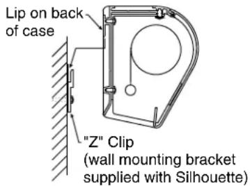
Wall Mounting
Mount 2, 3, or 4 aluminum brackets provided ("Z" Clips) on the wall at desired height, using appropriate fasteners. Verify that they are in line and level to fully engage with the mounting lip on back of screen case. 18 " of free space is required above the "Z" Clips to allow case lip to be engaged over the lip of the "Z" Clips.
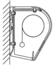
Engage the lip on back of screen case with lip of "Z" Clip and gently pull down to fully engage case to brackets.
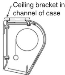
Ceiling/Suspended Mounting
Locate two offset ceiling brackets (supplied) and slide these into the channel on top of screen case by aligning the chamfered edges of each bracket parallel to the channel length. Allow bracket to drop against bottom of
Silhouette fully engaged on "Z" Clip
natural_image
Technical line drawing of a mechanical component with a circular feature and mounting bracket (no text or symbols)channel and then rotate bracket counter-clockwise. Slide one bracket to each end of screen case until it stops against end cap of case. Tighten two set screws to lock bracket in place. Make sure that the fl ange of the ceiling bracket that has four holes is extended beyond the end caps of the case. Repeat above procedure for second ceiling bracket, making sure to slide it towards opposite end of case.
To mount against ceiling, hold screen case against ceiling and mark mounting hole locations. Each brack et has 2 holes towards the front edge and 2 holes towards the back edge. Installer must use at least 2 fasteners per bracket with one fastener in one of the two holes clos est to back edge of bracket, and one fastener in one of the two holes closest to front edge of bracket. Installer must insure that fasteners are of adequate strength and suitable for the mounting surface chosen.
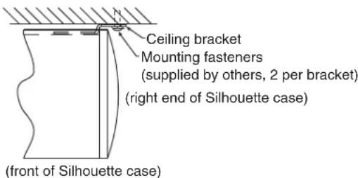
To mount suspended from ceiling, the brackets need to be installed on screen case as noted above. Attach "S" Hooks (supplied) through the holes in the brackets. Select the set of holes that allows the screen to hang in a vertical position. The installer is to provide the materials and fasteners to attach the "S" Hooks to the ceiling. Installer must insure that the fasteners and suspension material are of adequate strength and suitable for the mounting surface chosen.
DRAPER®
411 S. Pearl St., Spiceland, IN 47385 USA ■ 765-987-7999
www.draperinc.com ■ fax 765-987-7142
Silhouette/Series M and Series C by Draper
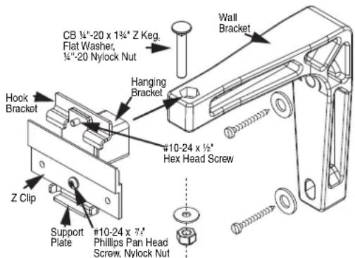
Extension Wall Brackets
6" or 10"-14" Extension Wall Brackets are needed to mount Silhouette extend from wall. Wall Brackets are not supplied with screen and must be ordered separately. Specify "Silhouette Extension Wall Brackets".
① Mount the Wall Brackets to the wall, making sure they are level and vertically plumb. Installer must insure fasteners (not included) are of adequate strength and suitable for chosen mounting surface.
② Attach hanging bracket to wall bracket as shown.
③ Attach (1) "Z" Clip and (1) Support Plate (supplied with screen) to hanging bracket as shown.
④ Engage the lip on back of screen case with lip of "Z" Clip and gently pull down to fully engage case to brackets.
⑤ Install hook bracket as shown making sure the two tabs of this bracket hook over the case extrusion.
⑥ Install #10-24 hex head screw through hook bracket, hanging bracket, and support plate as shown.
Operating Instructions—Series M Standard
To lower picture surface, pull screen down to desired position. Hesitate—then allow screen to slightly retract very slowly until it locks in place.
To raise picture surface, pull down on the pull bail, then raise quickly, as a window shade. Keep control of the picture sur face. Do not allow it to roll un con trolled into the case, or dam age is sure to result.
Operating Instructions—Series M with AutoReturn
To lower picture surface, pull screen down. Hesitate—then allow screen to retract very slowly until it locks in place.
To raise picture surface, pull screen down gently until it stops, then release.
Operating Instructions— Series C
To lower screen sur face, attach the crank handle to the "U" joint stud located on the left hand side of the screen. With the crank handle in its operating position, rotate counterclockwise. An internal pin within the gear box will stop the screen when fully extended. The crank handle can be removed if desired. The shipping support brackets must be removed from each end of dowel during initial operation.
To raise screen surface, attach the crank handle to the "U" joint stud located on the left hand side of the screen. With the crank handle in its operating position, rotate in a clockwise direction. An internal pin within the roller will stop the screen when fully retracted. The crank handle can be removed if desired.
Removing Case Fascia
Caution: When removing or reattaching fascia, do not handle fascia by unpainted ends.
⚠ Case fascia is removable to access roller assembly. To remove fascia, depress outward the spring lip located inside lower front corner of screen case and pull lower corner of fascia outward. Repeat this at right end of case. Support fascia from center and rotate lower front edge upward approximately 40° to disengage the Roll-Lok hinge at the top front of screen case. Fascia can now be completely removed from case.
To install fascia, generally reverse instructions above making sure the Roll-Lok hinge is completely engaged before rotating fascia down towards the closed position. Depress spring clips outward, push lower corners of fascia inward until lips of spring clips hook behind fascia.
Please Note: Be sure the clips are completely up against the ends of the fascia.
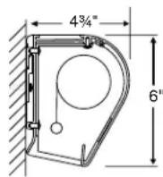
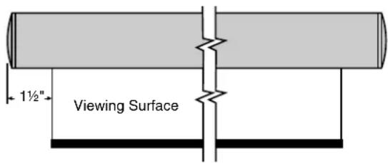
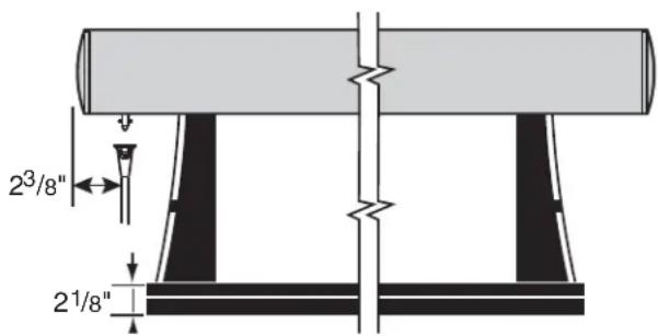
Case Dimensions
Silhouette/Series M
Silhouette/Series M with Auto Return
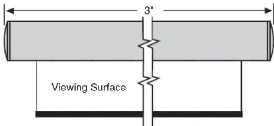
Silhouette/Series C
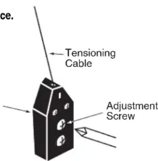
Tab-Tension Adjustment Procedure for Silhouette/Series C
① Determine which side requires adjustment.
② Secure dowel with one hand.
Caution: Do not touch or bend surface.
③ Using Philips-head screwdriver, depress spring-loaded adjustment screw (see drawing) and slowly turn clockwise to tighten tension, or counterclockwise to loosen tension.
The screw adjusts in 14 turn increments. Adjust only one increment ( 14 turn).
④ If problem is not corrected, leave screen in position for 24 hours to allow surface material to stretch into position.
⑤ If problem still is not corrected, repeat steps ② and ③.
② and ③.