DVI DA Plus Series - Mottaker Extron - Gratis bruksanvisning og manual
Finn enhetens veiledning gratis DVI DA Plus Series Extron i PDF-format.

Brukerspørsmål om DVI DA Plus Series Extron
0 spørsmål om dette apparatet. Svar på dem du kjenner, eller still ditt eget.
Still et nytt spørsmål om dette apparatet
Last ned instruksjonene for din Mottaker i PDF-format gratis! Finn veiledningen din DVI DA Plus Series - Extron og ta den elektroniske enheten tilbake i hendene. På denne siden er alle dokumenter som er nødvendige for bruken av enheten din publisert. DVI DA Plus Series av merket Extron.
BRUKSANVISNING DVI DA Plus Series Extron
DVI DA Plus Series • Setup Guide
Overview
These instructions provide a quick setup guide for the Extron DVI DA Plus Series distribution amplifiers. Installation and service must be performed only by experienced installers. More complete instructions can be found in the DVI DA Plus Series User Guide, which can be found online at www.extron.com.
Installation
Mounting
Install the distribution amplifier on a desk, under a desk, or in a rack.
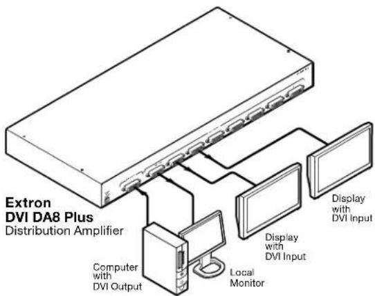
DVI Cable Connections
A typical application is shown in the figure at right. Connect these cables, but do not power on the equipment yet:
- Connect a DVI cable from the Input connector to the video source device.
- Connect aDVI cables from the distribution amplifier to the desired display devices.
flowchart
graph TD
    A["Extron DVI DA8 Plus Distribution Amplifier"] --> B["Computer with DVI Output"]
    A --> C["Local Monitor"]
    A --> D["Display with DVI Input"]
    A --> E["Display with DVI Input"]
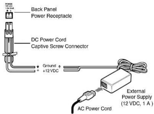
Power Cable Connections
Connect the 12 VDC power supply to the power receptacle of the unit. The figure below shows the 1 A power supply for the DVI DA4 Plus. The DVI DA6 Plus and DVI DA8 Plus require a 3 A power supply.
CAUTION: See the Caution in the "Power Input" section of the DVI DA Plus Series User Guide, for important information about power supplies.
NOTES: • The length of the exposed wires in the stripping process is critical. The ideal length is 3/16 inches (5 mm). If the exposed section is longer, the exposed wires may touch, causing a short circuit between them. If it is shorter, the wires can be easily pulled out even if tightly fastened by the captive screws. • Do not tin the wires. Tinned wire does not hold its shape and can become loose over time.
Applying Power
In the following order:
- Power on the display devices.
- Power on the distribution amplifier.
- Power on the source input device.
EDID Minder®
The Extron EDID Minder feature maintains continuous EDID (Extended Display Identification Data) communication with the attached source and ensures that the DVI source powers up correctly and maintains a proper video output, even if the display is off or when a new monitor is connected to the output.
When the distribution amplifier is powered on, it automatically scans all detectable outputs, selects the device with the lowest native resolution and passes the EDID information of that device to the input device. If no output displays are connected, the distribution amplifier provides the EDID information stored from the last display to which it was connected. If no output device has previously been connected to the unit, or the unit has been set to the factory default, it uses the factory default resolution (1024x768 @ 60 Hz).
DVI DA Plus Series • Setup Guide (Cont'd)
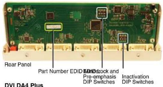

EDID Disable DIP Switches for DVI DA6 (shown) and DVI DA8
Disabling the EDID Minder
Some applications require that the EDID Minder feature is disabled for specific outputs or are ignored during the automatic scanning process. To prevent EDID being read from specific outputs:
- Remove and keep the screws holding the cover to the base (seven screws for the DVI DA4 Plus, ten screws for the DVI DA6 Plus and DVI DA8 Plus). Save the screws and set aside the cover.
- Check the part number of the printed circuit board (outlined in the figure above left). The boards must have a part number of 20-1496-01LF and higher (DVI DA4 Plus) or 20-1497-01LF and higher (DVI DA6 Plus or DVI DA8 Plus).
NOTE: If the part number of the board is lower than these values, you cannot deactivate the EDID Minder on your model. Replace the cover as described in step 5.
- Locate the EDID Minder Inactivation DIP switches. The DVI DA4 Plus has a single bank of four switches (see the figure above left). Each switch regulates the correspondingly numbered output (1-4).
The DVI DA6 Plus and DVI DA8 Plus have two banks of four switches (see the figure above right). In bank 1, each switch regulates the correspondingly numbered output (1-4). In bank 2, switches 1 and 2 correspond to outputs 5 and 6 for the DVI DA6 Plus; switches 1-4 correspond to outputs 5-8 for the DVI DA8 Plus.
-
By default the switches are in the off/down position, allowing the EDID information to be read from the corresponding output. To deactivate EDID Minder for one or more outputs, move the switch for that output to the on/up position.
-
Replace the cover, using the screws that were removed in step 1.
EDID Lock and Pre-emphasis
By default, EDID information stored at the input is lost when the unit goes through a power cycle or a new output display is connected to the device. EDID Lock maintains specific EDID information so that it is not lost after these events.
Pre-emphasis compensates for poor signals delivered to output devices.
To enable EDID Lock or Pre-emphasis:
- Remove the cover and locate the part numbers as described in steps 1 and 2 of the previous section.
- Locate the EDID Lock and Pre-emphasis DIP switches (outlined in the figure above left). For all three models, the EDID Lock DIP switch is labeled EDID Mode; the Pre-emphasis DIP switch is labeled Preemph.
- By default, the EDID Mode and Pre-emphasis DIP switches are in the down (disabled) position. To enable either feature, toggle the appropriate switch to the up position.
NOTE: Before enabling the EDID Lock feature, be sure the desired EDID is currently being used.
- Replace the cover, using the screws that were removed in step 1.
| Extron USA - West Headquarters+800.633.9876Inside USA/Canada Only+1.714.491.1500+1.714.491.1517 FAX | Extron USA - East+800.633.9876Inside USA/Canada Only+1.919.863.1794+1.919.863.1797 FAX | Extron Europe+800.3987.6673Inside Europe Only+31.33.453.4040+31.33.453.4050 FAX | Extron Asia+800.7339.8766Inside Asia Only+65.6383.4400+65.6383.4664 FAX | Extron Japan+81.3.3511.7655+81.3.3511.7656 FAX | Extron China+400.883.1568Inside China Only+86.21.3760.1568+86.21.3760.1566 FAX | Extron Middle East+971.4.2991800+971.4.2991880 FAX |
68-1536-50 Rev. C 02 11