DXF-TX-SMD - Ukategorisert AMX - Gratis bruksanvisning og manual
Finn enhetens veiledning gratis DXF-TX-SMD AMX i PDF-format.

Brukerspørsmål om DXF-TX-SMD AMX
0 spørsmål om dette apparatet. Svar på dem du kjenner, eller still ditt eget.
Still et nytt spørsmål om dette apparatet
Last ned instruksjonene for din Ukategorisert i PDF-format gratis! Finn veiledningen din DXF-TX-SMD - AMX og ta den elektroniske enheten tilbake i hendene. På denne siden er alle dokumenter som er nødvendige for bruken av enheten din publisert. DXF-TX-SMD av merket AMX.
BRUKSANVISNING DXF-TX-SMD AMX
Overview
Applicable units for this guide include the DXF-TX-MMD, DXF-RX-MMD, DXF-TX-SMD, DXF-RX-SMD, DXF-TX-MMS, DXF-RX-MMS, DXF-TX-SMS, and DXF-RX-SMS.*
All units support InstaGate Pro® and SmartScale® Technology.
* MM = multimode; SM = single mode; D at the end = Duplex; S at the end = Simplex. Duplex units handle simultaneous-bidirectional or unidirectional data transfer; Simplex units only handle unidirectional data transfer (multimode and single mode models support different cable lengths).
The Multi-Format TXs and HDMI RXs transmit HDMI and audio over fiber optic cable (Duplex models also transmit control data over fiber optic cable). The Multi-Format TXs also have an input for analog video and an HDMI port on the front for local loop out. All units can be set up in 1 of 3 ways (follow "Important" note below in all cases):
- Endpoint Mode (Switcher) – connect one or more units to an Enova DGX or Enova DGX 100 Series Switcher with an Integrated Master.
- Endpoint Mode (Standalone) – standalone TX/RX connected directly to each other with one connected to NetLinx Central Controller via LAN or directly to Controller.
- Extender Mode (Standalone) – connect TX/RX pair directly to each other.
The Hardware Reference Manual – DXLink Fiber Transmitters and Receivers contains complete documentation (including full specifications and supported input and output resolutions); see the product page at www.amx.com.
System Setup
IMPORTANT: For standalone pairs and for input/output boards with corresponding TX/RX units, mix-or-match is allowed for Duplex and Simplex hardware (both types of boards are also allowed in same enclosure). DXLink Fiber models must match: multimode to multimode and single mode to single mode. If connecting Duplex and Simplex products, see the "Hardware Reference Manual" for important information.
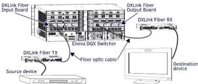
The TX and the RX work with a switcher that supports DXLink Fiber Technology for transmission of HDMI (or with a Central Controller) or as a standalone pair. The TX receives an HDMI signal (or analog video) and embedded audio from the source. Both the video and embedded audio are transported over fiber optic cable to a DXLink Fiber Input Board (or connector). The signal is routed via the DXLink Fiber Output Board (or connector) to an RX. On TXs, stereo audio or digital audio connections are provided as supplemental audio inputs. The RXs provide a stereo audio output. The TXs also have an HDMI local out on the front. All Duplex TXs and RXs support USB, IR, RS-232 (for serial data transfer) Ethernet. Simplex units only support Unidirectional Mode.
flowchart
graph TD
    A["DXLink Fiber Input Board"] --> B["DXLink Fiber RX"]
    B --> C["Destination device"]
    D["DXLink Fiber TX"] --> E["Fiber optic cable"]
    E --> F["Enova DGX Switcher"]
    G["Source device"] --> H["Computer"]
FIG. 1 DXLINK FIBER TX AND RX ENDPOINTS WITH COMPATIBLE DXLINK FIBER EQUIPMENT
IMPORTANT: FIG 6 shows duplex LC fiber cable; when using single LC fiber cables, be sure to verify that the individual fiber from the transceiver's TX label on one end of the run are connected to the transceiver's RX label on the other end and vice versa.
Mounting Options (Rack Trays and Mounting Brackets)
For details on the four versatile mounting kit options for V Style units (rack tray, rack tray with fill plates, surface mount, and pole mount), see www.amx.com
IMPORTANT: When mounting under a surface, the units should be mounted upright and lowered in the mounting bracket slots to provide an airflow gap between the surface and the vent holes. If not using V Style brackets, be sure to leave a gap between the top of the unit and the surface for heat to escape.
Fiber Optic Transceivers
The DXLink Fiber Transmitters and Receivers use SFP+ fiber optic transceivers. Fiber optic transceivers are self-contained modules that send and receive optical signals over fiber cable. DXLink SFP+ fiber optic transceivers are either multimode or single mode and must be wired with the corresponding cable type. Both multimode and single mode transceivers support bidirectional and unidirectional communication.
WARNING: DXLink Fiber units use laser transceivers, which are Class 1 Eye Safe per IEC 60825-1/CDRH requirements. While the Class 1 category indicates that the invisible laser used is safe, we recommend avoiding direct eye exposure when using any optical fiber products (see OSHA directive referenced in the "Hardware Reference Manual").
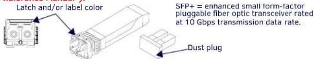
FIG. 2 FIBER OPTIC TRANSCEIVER MARKED BLACK (MULTIMODE) OR BLUE (SINGLE MODE)
The following information applies to LEDs above fiber optic transceiver on Duplex units.
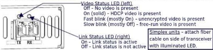
FIG. 3 FIBER OPTIC TRANSCEIVER LEDS ON DUPLEX UNIT (SIMPLEX LEDS - SEE MANUAL)
DIP Switch Toggles - Default OFF (for Auto-setup, see next page)
Before installing the units, find the scenario you are using in the applicable table below and set the DIP switch toggles accordingly. Toggle #4 can be used for placing Duplex units in Unidirectional Mode (for information, see the Hardware Reference Manual).
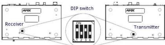
FIG. 4 DIP SWITCH TOGGLES ENABLE/DISABLE SPECIAL FUNCTIONALITY
COMMON SCENARIOS - BIDIRECTIONAL, TOGGLE SETTINGS (#4 MUST BE OFF)
| Standalone Setup (TX/RX Pair Direct Connection)* | #1 | #2 | #3 |
| AV signals only (plus serial/IR passthrough) | OFF | OFF | OFF |
| AV with Ethernet passthrough to a network device** (plus serial/IR passthrough) | ON | OFF | OFF |
| AV with NetLinx control of TX/RX unit and serial/IR ports, plus Ethernet passthrough to a network device*** | ON | ON | ON |
| TX/RX Connected to Enova DGX / DGX 100 Series (Switcher Setup) | #1 | #2 | #3 |
| AV signals only | OFF | OFF | OFF |
| AV with Ethernet passthrough to a network device** | ON | OFF | OFF |
| AV with NetLinx control of TX/RX unit and serial/IR ports | OFF | OFF | ON |
| AV with NetLinx control of TX/RX unit and serial/IR ports, plus Ethernet passthrough to a network device^ | ON | OFF | ON |
* Connection requires Duplex hardware with both fibers connected and in Bidirectional Mode (will not work in Unidirectional Mode).
** Connect the ICS LAN port on one of the DXLink Fiber units to a network device (e.g., laptop). *** Connect the ICS LAN 10/100 port on one of the DXLink Fiber units to the network device (e.g., laptop) and connect the other unit to the network (the unit with Toggle #1 enabled). ^ With both units connected to boards in an Enova DGX Switcher (provides Integrated NetLinx control), connect the ICS LAN 10/100 port on one of the DXLink Fiber units to the network device (e.g., laptop, IP controlled projector, AMX ICSlan EXB Device).
IMPORTANT: When connecting a TX or an RX in a standalone pair setup to a Master (or Virtual Master) for upgrade purposes, Toggles #1 and #3 must be ON Toggle #2 is only required on each unit if serial and/or IR control is required from the Master.
COMMON SCENARIOS - UNIDIRECTIONAL, TOGGLE SETTINGS (#4 MUST BE ON^^)
| Standalone Setup (TX/RX Pair Direct Connection) | #1 | #2 | #3 |
| AV signals only (plus serial/IR passthrough) | OFF | OFF | OFF |
| AV with NetLinx control of TX/RX unit and serial/IR ports | ON | ON | ON |
| TX/RX Connected to Enova DGX / DGX 100 Series (Switcher Setup) | #1 | #2 | #3 |
| AV signals only | OFF | OFF | OFF |
| AV with NetLinx control of TX/RX unit and serial/IR ports | ON | OFF | OFF |
^^ Does not apply to DXLink Fiber, Simplex units: Toggle #4 can be set to ON or OFF.
ICS LAN 10/100 Port
The ICS LAN 10/100 port uses twisted pair cable. FIG. 5 shows the LEDs for this port.
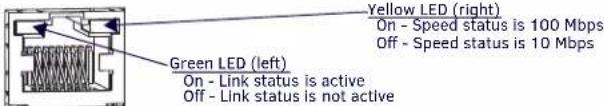
FIG. 5 ICS LAN 10/100 (RJ-45) PORT
Attaching Signal, Transport, and Control Cables
Important Cabling Requirements and Considerations:
- Fiber optic cable with LC termination for snap coupling with SFP+ transceivers
• LC Duplex conforming to ANSI TIA-EIA 604-10 (FOCIS 10A) - DXLink Fiber multimode transceivers use OM3 50/125 μm multimode fiber optic cable type over distances of up to 984 feet (300 m)^^^
- DXLink Fiber single mode transceivers use 9/125 μm single mode fiber optic cable type over distances of up to 6.21 miles (10 km)^^^
- Do not create a network (Ethernet) loop. A network loop is created when the enclosure and one or more of its DXLink Fiber units connect to a common LAN.
^^^ Cable quality is a determining factor for the maximum length of cable runs.
IMPORTANT: We recommend DXLink Fiber units be installed by a technician with knowledge of networks and experience with NetLinx Studio and Telnet. NetLinx experience should include changing device addresses, binding devices, updating firmware, etc. WARNING: DXLink Fiber units use laser transceivers, which are Class 1 Eye Safe per IEC 60825-1/CDRH requirements. While the Class 1 category indicates that the invisible laser used is safe, we recommend avoiding direct eye exposure when using any optical fiber products (see OSHA directive referenced in the manual).
To attach signal, transport, and control cables to a Transmitter:
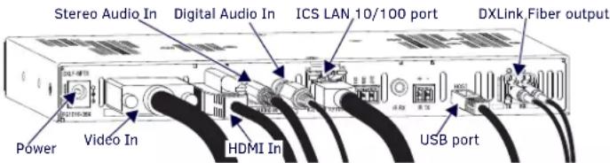
FIG. 6 ATTACH SIGNAL, TRANSPORT, AND CONTROL CABLES (DXLINK FIBER TX SHOWN)
- Set DIP switch toggles if necessary (for settings, see table on previous page).
- Video In - Attach HD-15 cable from source device to the Video In connector.
- HDMI In – Attach HDMI cable from source to HDMI In connector (a DVI cable can be used via a cable adapter; however, advanced audio support from HDMI will not be available.).
-
Clean end face on the fiber cable following manufacturer's recommendations.
-
Fiber optic transceiver – Remove the dust plug (save for further use) and attach a fiber optic cable* to the fiber optic transceiver (for transport to switcher) – always grasp fiber connector housing to plug (or unplug) a fiber optic cable (depending on housing, a click may be heard; if not, lightly tug to be sure connection is tight).
-
Digital Audio In jack (optional) – Insert the S/PDIF plug on the digital audio cable from the source into the jack.
-
Stereo Audio In jack (optional) – Insert analog audio cable from source.
-
ICS LAN10/100 port (optional) – Attach twisted pair cable from this port to LAN.
-
Local Out port (optional) – On TX front, attach HDMI cable from local monitor.
* See "Important Cabling Requirements and Considerations" on previous page.
To attach signal, transport, and control cables to the Receiver:
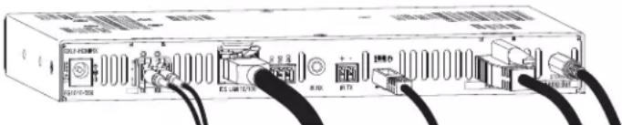
FIG. 7 ATTACH SIGNAL, TRANSPORT AND CONTROL CABLES
- Set DIP switch toggles if necessary (for settings, see previous page).
- Clean end face on the fiber cable following manufacturer's recommendations.
- Fiber optic transceiver - Remove dust plug (save for further use) and attach fiber optic cable** to fiber optic transceiver (for transport from switcher) – always grasp fiber connector housing to plug (or unplug) fiber optic cable (depending on housing, a click may be heard; if not, lightly tug to be sure connection is tight).
- HDMI Out - Attach HDMI cable from this port to the destination device.
- ICS LAN10/100 port (optional) – Attach twisted pair cable from this port to LAN.
- Stereo Audio Out Jack (optional) – Connect an analog audio cable from this port to the destination.
** See "Important Cabling Requirements and Considerations" on previous page.
Applying Power
This table shows LED states on initial power up. Follow directions for applying power at top of next column. If LEDs do not show normal status, check connections.
INDICATOR LEDS NORMAL POWER UP INDICATES
| Power Green Power is applied | ||
| Digital Video and Audio | Green | Video and HDMI embedded audio are present |
| TX - Analog Video;C, Y/C, Y/PB/PR, RGB, RGBHV, RGBS | Green or Off(only one of the three can be green at a time) | Corresponding signal is present |
| RX - Scaling: Bypass/Auto/Manual | One green, two off | Current scaling mode |
| IR TX / IR RX | Red / Yellow | IR activity |
| 232 (Serial) TX / 232 (Serial) RX | Red / Yellow | Serial activity |
| NetLinx Link/Act | Green | Active LAN connection to an AMX Network |
| NetLinx Status | Green | LAN activity |
| CEC | Off | Not currently supported |
| USB | Yellow | Connection established |
A desktop power supply (ENERGY STAR® qualified) is provided with each TX and RX. CAUTION: The provided desktop power supply must be used to power the DXLink Fiber TX and RX, and it must not be altered in any way.
To apply power to the Transmitter and/or Receiver:
-
Plug the cord from the desktop power supply (provided) into the power jack on rear of the unit (2.1 mm DC jack for 12 V local power).
-
Plug the desktop power supply into an AC external power source. The Power LED on the front of the unit illuminates green, indicating a ready state.
DXLink Auto-setup with Enova DGX 100 Series Switchers
Auto-setup is default for using DXLink units with Enova DGX 100 Series Switchers. When the following conditions are met, units automatically go into Auto-setup Mode and can communicate through the ICS LAN port with the integrated Master via Telnet:
- Endpoints must be set to DHCP Mode (default) and use the NDP Master connection mode (default).
- Endpoints must not be bound to a Master.
IMPORTANT: On the switcher, the ICS LAN port acts as a DHCP server (private LAN) and the LAN 100/1000 port acts as a DHCP client (public LAN) with each port on a separate network. In order to avoid a Network Loop, do not connect any device on a public network to any branch on a private network.
IP Addressing Modes
DHCP Mode (enabled when Toggle #3 is flipped ON)
In DHCP Mode, the unit attempts to get a DHCP lease (consisting of an IP address, gateway, and other network parameters). If the attempt fails, the unit configures itself for a link-local address, but periodically re-tries DHCP and re-assigns the IP to a valid DHCP grant if successful. At any time, if the unit determines that its IP address has changed, the unit will disconnect and reconnect to the Master.
Static IP Mode (set with ID button or Telnet command)
With Toggle #3 set to ON, press ID for 10 seconds to assign address of 192.168.1.2 or use a Telnet command to set unit to Static IP (see the Hardware Reference Manual).
Enova DGX and DXLink Fiber IP Setup (for systems without auto-setup)
The following procedure is intended to outline the steps necessary for network setup of DXLink Fiber TX and/or RX with an Enova DGX switcher. These steps require familiarity with NetLinx Studio. If unfamiliar with NetLinx Studio, complete instructions are included in the units' Hardware Reference Manual at www.amx.com.
To setup DXLink Fiber units with an Enova DGX switcher:
- Set DIP switch Toggles on DXLink Fiber units (#2 and #4 must be set to OFF).
- Apply power to the DXLink Fiber units.
- Connect DXLink Fiber units to the DXLink Fiber Boards on the Enova DGX.
- Optional – Configure a Static IP address (for each connected unit).
- Check to be sure DIP switch Toggle #3 is set to ON.
- Push and hold ID button for 10 seconds. The Static IP sets to 192.168.1.2.
- Configure the Device ID (for each connected unit).
- In NetLinx Studio's Online Tree, open a Telnet session (right-click unit and select Launch Telnet Window via NetLinx Studio).
- In the Telnet Window, type SET DEVICE
and press Enter (e.g., "SET DEVICE 6001" configures the Device ID to 6001). - Connect (bind) the DXLink Fiber units to the Enova DGX.
a. NDP (default) Mode – (1) In NetLinx Studio's Online Tree, right-click on the DXLink unit and select Network Bind/Unbind Device; (2) in the Bind/Unbind Device dialog, select the switcher; (3) click OK.
b. UDP/URL, TCP/URL, or AUTO Mode – (1) In Telnet Window, type SET CONNECTION; press Enter; (2) follow on-screen directions for desired mode.
RS-232 Serial Data (Optional)
The 232 port label is relative to data flow. Data enters the Transmitter at RX label, is sent via a fiber cable through the switcher, and leaves the Receiver at TX label. Flow is vice versa from Receiver to Transmitter. Applies to all DXLink Fiber units – wire RS-232 port for serial data transfer according to pinout above connectors (TXD-RXD-Ground).
IR Control (Optional)
The IR Receiver (FG-IR03) connects to IR RX port on Transmitter and IR Emitter (FG10-000-11) connects to IR TX port on Receiver or vice versa, depending on the installation. The signal is sent via fiber cable between switcher and units. When TX and RX units are used as a standalone pair, IR control acts as a passthrough.
USB Host & Keyboard/Mouse Ports Provide HID Support (Rear)
If needed, the Host (USB-mini A/B) port on TX units and the Keyboard/Mouse port (USB-mini A/B) on RX units provide HID support for a keyboard, mouse, and HUB.
Program Port (Front)
This USB mini-B port on the Transmitters supports DGX Configuration Software for programming a customer VGA EDID (for units connected to an Enova DGX 100 Series Switcher, use the System Configuration interface; see the switcher's manual).
ID Button (Front)
The ID button on front can be used to toggle between static and DHCP IP addressing, assign a device address, reset factory defaults, and restore factory firmware image.

Last Revised: 12/15/2015
© 2015 Harman. All rights reserved. SmartScale, NetLinx, Enova, AMX, AV FOR AN IT WORLD, and HARMAN, and their respective logos are registered trademarks of HARMAN. Oracle, Java and any other company or brand name referenced may be trademarks/registered trademarks of their respective companies.
AMX does not assume responsibility for errors or omissions. AMX also reserves the right to alter specifications without prior notice at any time. The AMX Warranty and Return Policy and related documents can be viewed/downloaded at www.amx.com.
3000 RESEARCH DRIVE, RICHARDSON, TX 75082 AMX.com | 800.222.0193 | 469.624.8000 | +1.469.624.7400 | fax 469.624.7153
AMX (UK) LTD, AMX by HARMAN - Unit C, Auster Road, Clifton Moor, York, Y030 4GD United Kingdom • +44 1904-343-100 • www.amx.com/eu/
93-1010-360 REV: D