SuperBlade SBI-4119MG-X - Server Supermicro - Gratis bruksanvisning og manual
Finn enhetens veiledning gratis SuperBlade SBI-4119MG-X Supermicro i PDF-format.

Brukerspørsmål om SuperBlade SBI-4119MG-X Supermicro
0 spørsmål om dette apparatet. Svar på dem du kjenner, eller still ditt eget.
Still et nytt spørsmål om dette apparatet
Last ned instruksjonene for din Server i PDF-format gratis! Finn veiledningen din SuperBlade SBI-4119MG-X - Supermicro og ta den elektroniske enheten tilbake i hendene. På denne siden er alle dokumenter som er nødvendige for bruken av enheten din publisert. SuperBlade SBI-4119MG-X av merket Supermicro.
BRUKSANVISNING SuperBlade SBI-4119MG-X Supermicro
SUPERMICR B11SCG-CTF/ZTF Quick Reference Guide 1.00
CONTACT INFORMATION
Website: www.supemicro.com
• General Information: marketing@supermicro.com
• Technical Support: support@supermicro.com
• Phone: +1 (408) 503-8000, Fax: +1 (408) 503-8008
FOR YOUR SYSTEM TO WORK PROPERLY, PLEASE DOWNLOAD APPROPRIATE
DRIVERS/IMAGES/USER'S MANUAL FROM THE LINKS BELOW
- Manuals: http://www.supperiora.com/support/manuals
- Manuals. http://WWW.supertmicro.com/support/manuals
- Drivers & Outides: https://www.supermicro.ca/invai/ Driver
- Privacy https://www.ewww.com/health@holising/refeb
- Safety. http://www.supernfio.com/aboutpolicies/safety_information.com

Motherboard Layout and Features
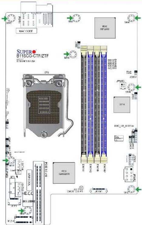

Jumpers, Connectors and LED Indicators
| Jumpers | ||
| Jumper | Description | Default Setting |
| JS | PCIe Expansion Option | Pins 1-2 (x8 Slot)(x8 Slot 2 or x18 Slot) |
| JBR1 | BIOS Recovery | Pins 1-2 (Normal) |
| JST1 | Clear CMOS | Short: Clear CMOS Open: Normal |
| JPG1 | VGA Enable/Disable | Pins 1-2 (Enabled) |
| JPME1 | ME Recovery | Pins 1-2 (Normal) |
| JPME-2 | Manufacturing Mode Select | Pins 1-2 (Normal) |
| JWD1 | Watch Dog Enable | Pins 1-2 (Reset) |
Connectors
| Connector | Description |
| RT1 | Onboard CMOS Battery |
| I-SATA/II-SATA3 | Intel® PCH SATA 3.0 Ports |
| J4 | CPLD Programming Header (Manufacturing Use Only) |
| JDBC1 | VRM Debug Jumper (Manufacturing Use Only) |
| JFP1 | Front Panel Cable Connector |
| JKVN1 | VGA/USB Module Connector |
| JPQ1 | Power Button Bypass (Manufacturing Use Only) |
| JPWR2 | 12V GPU Card Power Connector |
| JPWR3 | 4-pin Power Connector for SATA/SAS |
| JSD1 | SATA DOM Power Connectors |
| JTPM1 | Trusted Platform Module (TPM)/Port 8G Connector |
| JVR1 | VRM Programming Heater (Manufacturing Use Only) |
| M.2-H | M.2 Slot |
| PWR1 | Power Receptable to Chassis Backplane |
LED Indicators
| LED | Description | Status |
| BMC HS LED1 | BMC Heartbeat LED | GREEN Binking: Normal |
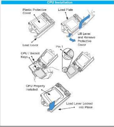
CPU Support and Installation
The B11SCG-CTF motherboard supports the Intel® Xeon® E-2100 processor or an 8th-9th Generation Intel Core G/Portuma®/Coloner® processors in a LGA 1151 (H4) socket.
The G11SCG-ZTF supports an 9th/9th generation Intel Core 7/i5i3/Pentium/Calamon processors in an LGA151 (H4) socket.
Memory Support and Installation
The B11SCG-CTT supports up to 128GB of ECC UDIMM memory with speeds up to 2666MHz.
The B'1SCG-ZTF supports up to 64GB of D0R4 Non-ECC UDIMM memory with speeds of up to 2666MHz.
See below for additional memory information.
■ The blue slots must be populated first.
- Always use DDR4 memory of the same type, size, and speed. Mixed DIMM speeds can be installed. However, all DIMMs will run at the speed of the slowest DIMM.
- The motherboard will support odd-numbered modules. However, to achieve the best memory performance, a balanced memory population is recommended.
Recommended Population (Balanced)
| DIMMA1 | DIMMB1 | DIMMA2 | DIMMB2 | Total System Memory |
| 4GB | 4GB | 8GB | ||
| 4GB | 4GB | 4GB | 4GB | 16GB |
| 8GB | 9GB | 16GB | ||
| 8GB | 8GB | 8GB | 8GB | 32GB |
| 16GB | 16GB | 32GB | ||
| 16GB | 16GB | 16GB | 16GB | 84GB |
| 32GB | 32GB | 64GB | ||
| 32GB | 32GB | 32GB | 96GB | |
| 32GB | 32GB | 32GB | 32GB | 126GB |
Note Graphics shown in this quick reference guide are for illustration only. Your components may or may not look exactly the same as drawings shown in this guide.
Note. Refer to Chapter 1 of the User Manual for detailed information on jumpers, connectors, and LED indicators.
Note: Refer to Chapter 2 of the User Manual for detailed information on memory support and CPU method from installation instructions.