SRPO-48G-2 - Pizzaovn Sierra Range - Gratis bruksanvisning og manual
Finn enhetens veiledning gratis SRPO-48G-2 Sierra Range i PDF-format.

Brukerspørsmål om SRPO-48G-2 Sierra Range
0 spørsmål om dette apparatet. Svar på dem du kjenner, eller still ditt eget.
Still et nytt spørsmål om dette apparatet
Last ned instruksjonene for din Pizzaovn i PDF-format gratis! Finn veiledningen din SRPO-48G-2 - Sierra Range og ta den elektroniske enheten tilbake i hendene. På denne siden er alle dokumenter som er nødvendige for bruken av enheten din publisert. SRPO-48G-2 av merket Sierra Range.
BRUKSANVISNING SRPO-48G-2 Sierra Range
SERVICE & INSTRUCTION
OWNER'S MANUAL

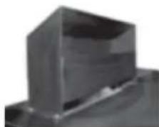
DECK OVENS
SRPO-48G
SRPO-60G
SRPO-72G
IMPORTANT INSTRUCTIONS FOR OVEN INSTALLATION, OPERATION AND MAINTENANCE
MVP GROUP LLC, 12000 BISCAYNE BLVD., SUITE 108, MIAMI, FL 33181
TEL: 786-600-7554 FAX: 786-661-4100
MVP GROUP CORP, 5659 ROYALMOUNT, MONTREAL, QC CANADA H4P 2P9
TEL: 514-737-9701 FAX: 514-342-3854
WWW.MVPGROUPCORP.COM
NOTICE: WHEN THIS APPLIANCE IS INSTALLED WITH CASTERS, IT MUST BE INSTALLED WITH THE CASTERS SUPPLIED, A CONNECTOR COMPLYING WITH EITHER ANSI Z21.69 OR CAN/CGA-6.16. AND A QUICK-DISCONNECT DEVICE COMPLYING WITH EITHER ANSI Z21.41 OR CAN 1-6.9. IT MUST ALSO BE INSTALLED WITH A RESTRAINING MEANS TO GUARD AGAINST TRANSMISSION OF STRAIN TO THE CONNECTOR, AS SPECIFIED IN THE APPLIANCE MANUFACTURER'S INSTALLATION INSTRUCTIONS.
IN THE COMMONWEALTH OF MASSACHUSETTS THIS APPLIANCES MUST BE INSTALLED UNDER AN EXHAUST HOOD AND MUST BE INTERLOCKED WITH THE GAS SYSTEM AND COMPLY WITH STATE PLUMBING CODES AND INSTALLED BY A LICENSED PLUMBER OR GAS FITTER.
IMPORTANT FOR YOUR SAFETY
Installation and service must be performed by a qualified installer, service agency or the gas supplier.
WARNING
This appliance is only for professional use and shall be used only by qualified people. All parts that have been protected by the manufacturer or his agent must not be adjusted by the end user.
Improper installation, adjustment, service or maintenance can cause property damage, injury or death. Read the installation, operating and maintenance instructions thoroughly before installing this equipment.
WHAT TO DO IF YOU SMELL GAS
· Do not try to light any appliance.
· Do not touch any electrical switch; do not use any phone in your building.
- Immediately call your gas supplier from a neighbor's phone. Follow the gas supplier's instructions.
· If you cannot reach your gas supplier, call the fire department.
FOR YOUR SAFETY
Do not store or use gasoline or flammable vapors or liquids in the vicinity of this or any other appliance.
IN THE EVENT OF A POWER FAILURE DO NOT ATTEMPT TO OPERATE THIS DEVICE. SHUT OFF POWER.
IMPORTANT INSTALLATION INSTRUCTIONS
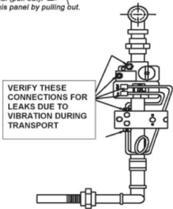
During transportation due to vibration it is possible that leaks may occur.
Please remove front panel of oven and verify that there are no leaks of gas on the joints (fittings) between aluminum tubing and the valve to the pilot and the fitting of the thermostat to the valve.
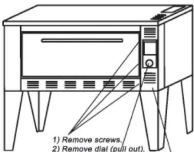
1) Remove screws.
2) Remove dial (pull out).
3) Remove this panel by pulling out.
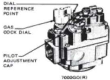
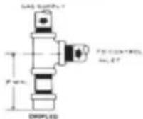
7000GO(R) & 7000GD(R)HC GAS OPERATED CONTROL VALVE
TO START OPERATION:
- Set the room thermostat to the lowest temperature setting, or "OFF."
- Partially depress and turn control Gas Cock Dial to "OFF" position.
- Wait five minutes to allow gas which may have accumulated in the main burner compartment to escape.
- Turn Gas Cock Dial to "PILOT" position.
- Depress Gas Cock Dial and light Pilot. Hold in depressed position for about 1/2 minute.
Note: Sufficient time must be allowed for a proper size pilot flame to heat the thermocouple and hold the safety magnet in a locked-up position. Also, time must be allowed for air to escape from the lines during the first operation. - Release Dial and turn to full "ON."
- Reset Room Thermostat.
INSTALLER NOTE:
Please leave these lighting instructions with unit. DO NOT REMOVE.
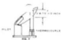
PILOT BURNER ADJUSTMENT:
- Remove Pilot Adjustment Cap.
- Adjust pilot key to provide properly sized flame.
- Replace Pilot Adjustment Cap.
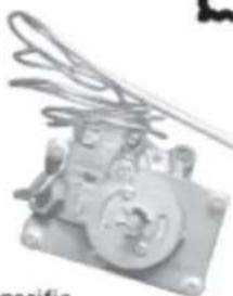
C4200 (FD) COMMERCIAL GAS THERMOSTAT
dividual models of the VC4200 series are available for specific plications. These thermostats are used on ovens, fryers, sterilizers d similar equipment.
lap-Throttle models provide snap action to "off" for low temperature settings and throttling main valve action for higher temperature ttings.
rotting only models have a constant by-pass and maintain a nimum flame on the burner when the unit is in operation.
WARNING
- Shut off gas and electricity before starting installation or service. Turn back on to test or operate.
- Installation and servicing of gas appliances and controls must only be performed by qualified personnel. After installation or servicing, test manual valve, pressure regulation (if so equipped), and automatic safety shut off valve for proper operation.
3 A drip leg should be provided in the supply line to the control. - Leak test with a soap solution after installation or servicing with main burner on. Coat pipe and tubing joints, gasket etc. with soap solution. Bubbles indicate leaks.
- DO NOT use this control if it has been exposed to water corrosion through immersion, dripping, etc. It may be damaged and must be replaced.
- DO NOT insert any object other than suitable pipe or tubing in the inlet or outlet of this control. Internal damage may occur and result in a hazardous condition.
- DO NOT connect appliance before pressure testing gas piping. Damage to gas valve may result
- DO NOT grip control body with a pipe wrench or vise. Damage may result causing gas leakage. Use inlet or outlet bosses, or special body wrench.
- DO NOT use Gas Cock Dial to adjust gas flow Turn dial to full "ON".
- Dials must only be operated by hand. DO NOT use pliers, wrenches or other tools to turn dials.
- In changing from natural to L.P. gas, or vice versa, regulator assembly (if so equipped), burner and pilot orifices must be changed.
- When using L.P. gas caution must be taken to ensure that no raw gas is present in the surrounding area before attempting to put appliances into operation, or relighting pilot.
- In case of failure of gas valve to shut off, DO NOT shut off electrical power; turn off gas supply allowing circulating pump (if so equipped) to continue running until system has cooled.
- Keep all combustible materials away from gas appliance. DO NOT allow lint or dust to collect in burner area.
natural_image
Close-up of a mechanical component with coiled spring and mounting holes (no visible text or symbols)Thermostat shown RB4200503
SAVE THESE INSTRUCTIONS FOR FUTURE USE
GENERAL
Read these instructions and keep them for future reference. Before installing the oven, consult your local building authority and obtain a building permit if necessary. Do not modify or alter the construction of the oven or any of its components. Install the oven as described in these instructions. Use only Sierra components. Failure to do so will void the Certification approvals and the warranty of this oven.
PURCHASER'S RESPONSIBILITY
- To see that the gas and electric services for the oven are installed on site in accordance with the manufacturer's specifications.
- To unload, uncrate and install the oven in its proper location in accordance with the Installation Operation Manual.
- To see that the gas and electric services are connected properly by a qualified installer of your choice. All such connections must be in accordance with applicable Code requirements.
- To arrange for inspection and operation check-out by an authorized service technician as described below.
- Do not attempt to operate the oven until connection of utility service has been fully inspected by an authorized service technician
- The warranty shall not apply if the ovens are started up and operated prior to the utilities and oven being inspected and checked out by an authorized service technician
INSTALLATION CODES AND STANDARDS:
This Gas-Fired Oven complies with the National Standards of Canada and United States "CSA 1.8 / ANSI Z83.11, Gas Food Service Equipment and NSF/ANSI 4, Commercial Cooking, Rethermalization, and Powered Hot Food Holding and Transport Equipment. It is certified by INTERTEK and bear the cETLus ant ETL sanitation certification marks.
This Gas-Fired Oven must be installed in accordance with local codes, if any; if none, follow the latest revision of CAN/CSA B149.1 (Canada) or ANSI Z223.1/NFPA54 (USA) Installation codes, as applicable.
GAS PIPING: OVENS ARE SUPPLIED WITH GAS CONNECTION THREADED TO ISO-7.
CAUTION: The available gas pressure should be within the limits shown in the SPECIFICATIONS section. Excessive pressure will damage Combination Valve and Regulator. If the supply pressure exceeds the 14.0" w.c. (50 MBAR) maximum, a suitable intermediate main regulator must be installed ahead of the Main Manual Shut-Off Valve.
- The burner gas supply piping should branch off from the main line as close to the gas meter as possible. Do not connect to the bottom of an horizontal section. Use new black pipe and malleable fittings free of cutting and threading burrs or defects.
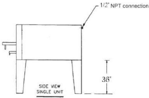
- A separate shut-off valve or gas cock for EACH OVEN MUST be PROVIDED. For stacked ovens, EACH DECK shall be considered a separate oven.
- THE FLUE PIPE from the draft hood must not run downward at any point from the oven to the final outlet. For horizontal runs, it must rise at least 1/4" inch per foot. FOR BEST RESULTS; the flue should rise straight up.
- DO NOT USE A DAMPER IN THE FLUE, OR CONNECT A BLOWER DIRECTLY TO THE FLUE. If the flue runs directly to the free air outside the building, use an approved wind deflector.
- When a ventilation hood is used, a flue deflector is mounted in place of the draft hood. The hood should be constructed at least as wide as the oven, and should overhang 6" to 12" (15cm to 30cm), forward of the oven. Its lower front edge should be 6'6" ft. (2M) from the floor.
• The main valve comes equipped with its own pressure tap.
CAUTION: Because it is difficult to accurately control pressure during supply pipe leak test, it is recommended that the Combination Valve be disconnected. Exposing the combination valve to a pressure over 12 psig, 14.0" w.c. (50 MBAR) will damage the valve and void all warranties.
DANGER! Explosion hazard.
Do not use oxygen for pressure testing. An explosion could occur during initial start-up.
WARNING: * DO NOT MODIFY THIS APPLIANCE.
* DO NOT BLOCK THE AIR REGISTERS ON THE OVEN AS THIS WILL CAUSE THE OVEN TO OVERHEAT.
WARNING: DO NOT USE THIS APPLIANCE IF ITS CONTROL HAS BEEN UNDER WATER. IMMEDIATELY CALL A QUALIFIED SERVICE TECHNICIAN TO INSPECT THE APPLIANCE AND TO REPLACE ANY PART OF THE COMPONENTS WHICH HAS BEEN UNDER WATER.
WARNING: ADEQUATE MEANS MUST BE PROVIDED TO LIMIT THE MOVEMENT OF CASTERED APPLIANCES. A RESTRAINING DEVICE IS REQUIRED FOR ALL TYPES OF MOVEABLE GAS APPLIANCES.
INSTALLATION
RECEIVING: Immediately after receiving the oven, check for possible shipping damages. If this oven is found to be damaged, save the packaging material and contact the carrier within 15 days of delivery. Prior to installation, verify that the type of gas (natural or propane) agree with the specifications on the oven data plate, located on right exterior side panel. Do not use the door or the handle to lift oven.
LOCATION: Verify that the doors and access routes into kitchen area are checked for clearance. (When crate is turned on its side, the oven will pass through a 34" [864mm] door opening). The equipment area must be kept free and clear of combustibles. Maintain clearances from combustible or noncombustible construction of at least 3" (76mm) from the side and 3" (76mm) from the back of the oven. The installation location must allow adequate clearances for servicing and proper operation.
INSTALLING BASIC OVEN:
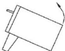
1) Tilt oven on back side and fasten front legs to oven.
STEP #1
2) Tilt oven forward on front legs and lift from back until oven is resting on front legs.
STEP #2
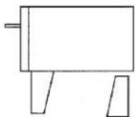
3) Place one of the remaining legs upside down so that large end of leg is resting on floor and place under back center of oven.
STEP #3
4) Attach the remaining leg and then lift the oven slightly removing the leg that was used as a brace, turn right side up, and install. When legs are securely fastened place oven.
STEP #4
5) Install using screws supplied with oven one of the following.
Draft Hood
Used with a flue pipe to the exterior of the building
Flue Deflector
Used under a Ventilation hood
natural_image
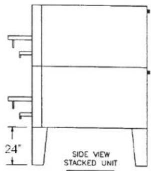
Abstract 3D geometric shape with shading, no text or symbols visibleSTACKING OVENS: Lift and place oven on top of bottom one.
No fasteners are required, the weight of the oven will keep it in place.
A separate shut-off valve or gas cock for EACH OVEN MUST be
PROVIDED. For stacked ovens, EACH DECK shall be considered a separate oven.
Single oven suggested 36" legs stacked ovens suggested 24" legs
INSTALLATION OF STONE HEARTH & UNDERSHEETS:
Step #1: Install stainless steel trim on top of the bottom door frame.
Step #2: Starting on the left side of oven, install undersheets placing the side with the flange on the right. Make sure the longer notch is towards the front resting on the stainless trim. The shorter notch rests on the rear ledge.
Basic position of undersheets
natural_image
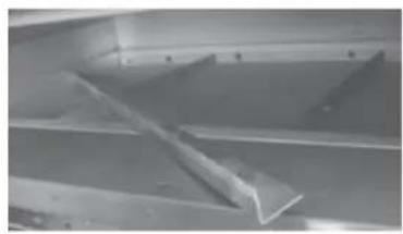
Close-up of a metallic mechanical component with triangular blades and a central rod (no visible text or symbols)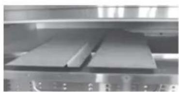
natural_image
Industrial machine with two rectangular components on a shelf (no visible text or symbols)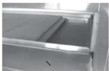
natural_image
Interior view of a metal shelving unit with visible shelves and drawer (no text or symbols)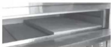
natural_image
Interior view of a kitchen appliance with shelves and a drawer (no visible text or symbols)Step #3: Now place the stone hearth on top of steel undersheets.
NOTE: The hearth stones have the letter "B" stamped along one side the 36" length. The sides marked "B" should be placed together.
natural_image
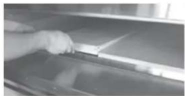
Close-up of a hand cleaning a dark surface with a white plastic clip (no text or symbols visible)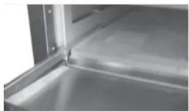
natural_image
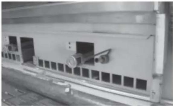
Close-up of a metallic shelf or panel with visible edges and a central rectangular opening (no text or symbols)Step #4: Angle stoppers should then be placed on both sides of the stone hearth to compensate for the expansion of the metal when very hot.
BREAKING-IN: This process is simple and if done as indicated below, will assure a properly functioning oven.
FOR "IMPERIAL" DECKS (STONE HEARTHS): Set oven to 300° F (150° C) FOR 2 HOURS, raise oven temperature to 400° F (200° C) for 1 hour, raise oven temperature to 500° F (260° C) for 1 hour, raise oven temperature to 600° F (315° C) for 1 hour. DO NOT PUT WATER ON STONE HEARTH WHEN HOT.
FOR "STEEL" DECKS: Set oven to 300° F (150° C) FOR 1 HOUR, Raise oven temperature to 450° F (232° C) for 1 hour, raise oven temperature to 600° F (315° C) for 1 hour.
CLEANING INSTRUCTIONS
NOTE: THE OVEN MUST BE COOL AS WATER OR CLEANING LIQUIDS APPLIED TO THE STONE HEARTH WHILE HOT CAN CAUSE HEARTH TO BREAK. DO NOT USE STRONG CLEANING AGENTS, STEEL WOOL OR WIRE BRUSHES ON STAINLESS STEEL SURFACES.
- Clean exterior surfaces of the oven by wiping it down with a mild detergent and clean water, or a commercial cleaner.
- Clean the interior by sweeping up all loose particles. DO NOT use wire brushes or liquids on the stone hearths as this can cause them to break.
- On exterior of oven, removal of deposits of baked-on splatter, oil, grease or light discolorations may be removed with any of several commercial cleaners. Consult with your local supplier.
- Periodically, remove flue from unit and clean in a detergent and hot water. NOTE: Be sure to clean and inspect the ventilation hood on a regular basis.
PREVENTATIVE MAINTENANCE
Although this oven has been designed to be as trouble free as possible, periodic Preventative Maintenance is essential to maintain peak performance. It is necessary to keep controls free of dirt, dust, and debris to insure proper cooling of components. Overheating is detrimental to the life of all the components. The periodic intervals for preventative cleaning may vary greatly depending upon the environment in which the oven is operating.
TO CHANGE CARRY OVER TUBE OR BURNERS
Step #1: Open door and remove two screws holding panel.
Step #2: Open bottom panel and remove screw.
Step #3: Remove control panel.
Step #4: Unscrew bracket holding manifold.
Step #5: Undo manifold.
Step #6: Remove last screws holding manifold taking it off.
Step #7: Remove second to last bracket support holding carry over tube.
natural_image
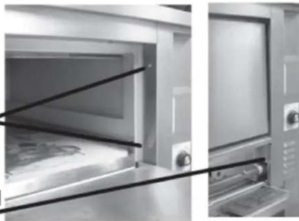
Interior view of a laboratory or industrial chamber with two black lines indicating diagonal braces (no visible text or symbols)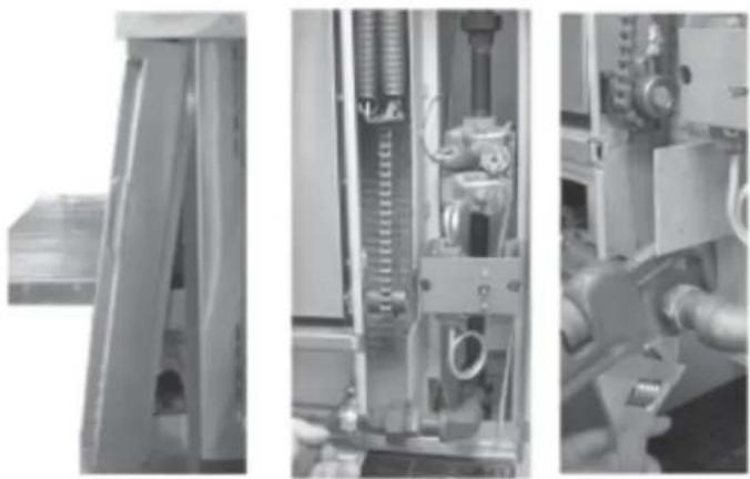
natural_image
Industrial machinery interior view showing internal components and structural details (no visible text or symbols)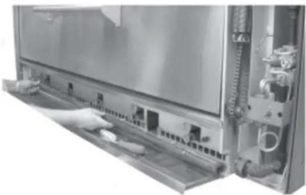
natural_image
Close-up of a mechanical device with a hand operating the next panel, showing internal components and tubing (no visible text or symbols)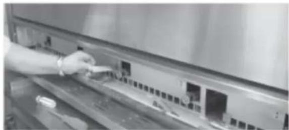
natural_image
Hand placing a small object on a shelf with electronic equipment (no visible text or symbols)Step #8: Remove remaining brackets.
natural_image
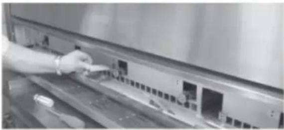
Close-up of a hand inserting a small object into a metal rack (no visible text or symbols)Step #9: Remove tube holder with allen key and push tube behind.
natural_image
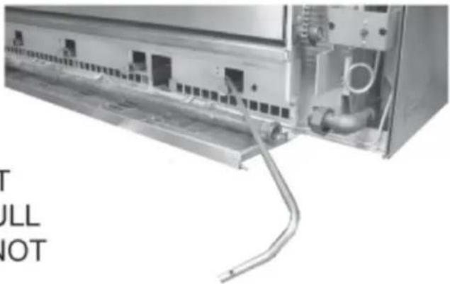
Exterior view of a mechanical or industrial enclosure with visible structural components and no text or symbolsStep #10: Pull tube forward and remove end bracket.
natural_image
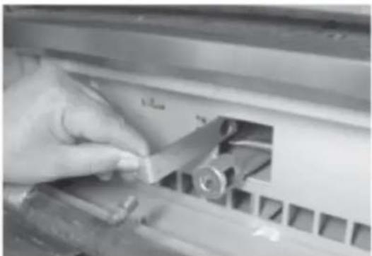
Close-up of a hand using a tool to adjust or install a mechanical component (no visible text or symbols)Step #11: Pull out carry over tube and replace.
natural_image
Close-up of an industrial machine with visible internal components and wiring (no text or symbols)TO CHANGE BURNERS JUST REMOVE MANIFOLD AND PULL OUT BURNERS. THEY ARE NOT SCREWED DOWN.
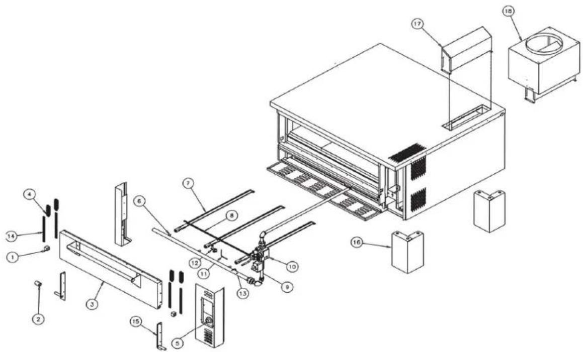
PARTS BREAKDOWN FOR THE MODELS SRPO-48G / SRPO-60G / SRPO-72G
0
| NO | PART # | DESCRIPTION | NO | PART # | DESCRIPTION |
| 1 | SIE-TEF005 | S/S SQUARE BUSHING FOR HINGE | 14 | SIE-E200CH | DOOR CHAIN |
| 2 | SIE-TEF349 | DOOR DRUM | 14 | SIE-E300CH | DOOR CHAIN |
| 3 | SIE-TEF257 | DOOR ASSEMBLY FOR SPRO-48G | 15 | SIE-F272-L | DOOR HINGE LEFT SIDE |
| 3 | SIE-TEF259 | DOOR ASSEMBLY FOR SPRO-60G | 15 | SIE-F272-R | DOOR HING RIGHT SIDE |
| 3 | SIE-TEF261 | DOOR ASSEMBLY FOR SPRO-72G | 16 | SIE-P12 | PAINTED LEGS 12" |
| 4 | SIE-CA200SP | DOOR SPRING | 16 | SIE-018 | PAINTED LEGS 18" |
| 5 | SIE-RBKNOB | KNOB FOR THERMOSTAT | 16 | SIE-P24 | PAINTED LEGS 24" |
| 6 | SIE-TE44 | ORIFICE FOR BURNER (NATURAL) | 16 | SIE-P30 | PAINTED LEGS 30" |
| 7 | SIE-TE55 | ORIFICE FOR BURNER (PROPANE) | 16 | SIE-P36 | PAINTED LEGS 36" |
| 8 | SIE-ML247 | CARRY OVER TUBE (MODEL SRPO-48G) | 16 | SIE-SS12 | STAINLESS STEEL LEGS 12" |
| 8 | SIE-ML248 | CARRY OVER TUBE (MODEL SRPO-60G) | 16 | SIE-SS18 | STAINLESS STEEL LEGS 18" |
| 8 | SIE-ML249 | CARRY OVER TUBE (MODEL SRPO-72G) | 16 | SIE-SS24 | STAINLESS STEEL LEGS 24" |
| 9 | SIE-RB4200503 | THERMOSTAT | 16 | SIE-SS30 | STAINLESS STEEL LEGS 30" |
| 10 | SIE RB7000BGOR12 | GAS VALVE | 16 | SIE-SS36 | STAINLESS STEEL LEGS 36" |
| 11 | SIE-RB44348 | THERMOCOUPLE | 16 | SIE-PC5 | CASTERS 5"/SET |
| 12 | SIE-RB5CH1 | PILOT | 17 | SIE-FD282A | FLUE DEFLECTOR |
| 13 | SIE-P47N | ORIFICE FOR CARRY OVER # 58 (NG) /SRPO-48G | 18 | SIE-DH291A | DRAFT HOOD |
| 13 | SIE-P48N | ORIFICE FOR CARRY OVER # 55 (NG) /SRPO-60G | 19 | SIE-ST1236112 | HEARTH STONE 12"X36"X1.5" |
| 13 | SIE-P49N | ORIFICE FOR CARRY OVER # 53 (NG)/SRPO-72G | 19 | SIE-ST2436112 | HEARTH STONE 24"X36"X1.5" |
| 13 | SIE-P47P | ORIFICE FOR CARRY OVER # 72 (LP) /SRPO48G | |||
| 13 | SIE-P48P | ORIFICE FOR CARRY OVER # 68 (LP) /SRPO-60G | |||
| 13 | SIE-P49P | ORIFICE FOR CARRY OVER # 65 (LP) /SRPO-72G |