TM7553 - Telefon On-Q - Gratis bruksanvisning og manual
Finn enhetens veiledning gratis TM7553 On-Q i PDF-format.

Brukerspørsmål om TM7553 On-Q
0 spørsmål om dette apparatet. Svar på dem du kjenner, eller still ditt eget.
Still et nytt spørsmål om dette apparatet
Last ned instruksjonene for din Telefon i PDF-format gratis! Finn veiledningen din TM7553 - On-Q og ta den elektroniske enheten tilbake i hendene. På denne siden er alle dokumenter som er nødvendige for bruken av enheten din publisert. TM7553 av merket On-Q.
BRUKSANVISNING TM7553 On-Q
1. INTRODUCTION
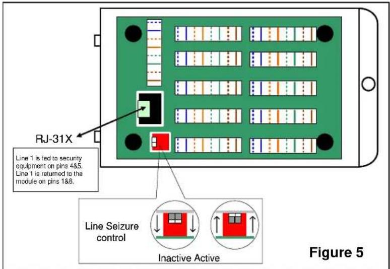
The On-Q/Legrand 4 X 10 Punchdown Telecom Modules (P/N TM7553 and TM7554 as shown in Figure 1) are members of our flexible family of Telephone Distribution Modules, each of which is designed to more closely match homeowner needs.
2. DESCRIPTION
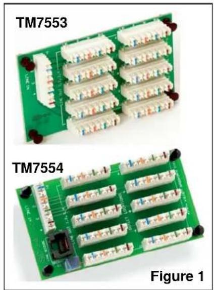
The 4 X 10 Punchdown Telecom Modules distribute four incoming telephone lines to as many as 10 locations throughout the home (see Figure 2). The P/N TM7554 version also includes an RJ-31x security system interface. Both versions have the following features:
• 110 punchdown style connectors for user friendly configuration
- All ports wired to meet TIA 568A specifications
• Accepts four incoming telephone lines
• Flexible distribution to 10 telephone locations
- Single bay bracket (P/N 364890-01) included for installation in On-Q style enclosure (see Figure 2)
- 50 microns gold plated contact points on RJ-31x interface port (TM7554 only)
natural_image
Two green circuit boards labeled TM7553 and TM7554, showing various connector layouts (no text or symbols on the boards themselves)3. INSTALLATION
A. MOUNT THE 4 X 10 PUNCHDOWN TELECOM MODULE INTO THE ENCLOSURE
- Pull out the plungers located at each corner of the 4 X 10 Telecom Module and insert the module into the included single bay bracket (see Figure 2), depressing the plungers to secure the module to the bracket.
- Insert the bracket into the On-Q style enclosure by inserting the tabs on the bracket into the slots on the left hand side of the enclosure and securing the bracket with the push-pin on the right end of the bracket.
B. TERMINATE WIRING
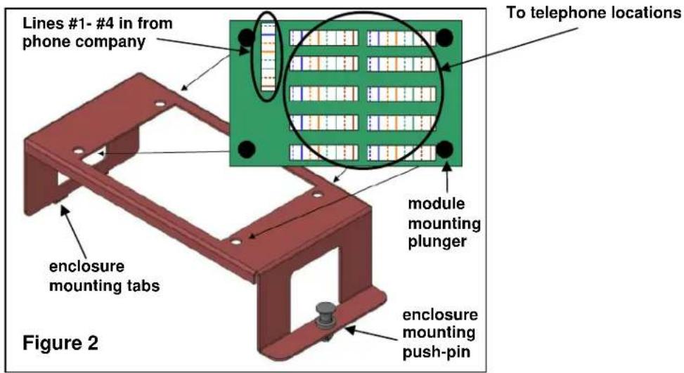
NOTE: All wiring should be terminated to the T568A wiring standard as shown in Figure 3.
- Terminate the incoming Cat 5e line from the telephone company NID to the 110 style punchdown connector that is labeled "LINE IN 1,2,3,4".
- Terminate each Cat 5e line (up to 10 total) that will be used for each voice jack location to the 110 style punchdown connectors that are labeled "OUTLET LOCATIONS".
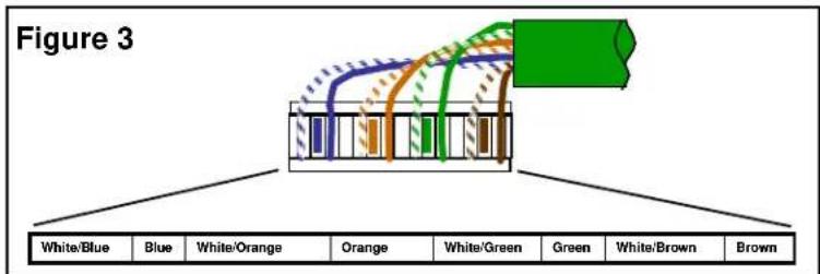
C. TERMINATE AND CONFIGURE RJ-31X LINE SEIZURE (TM7554 ONLY)
NOTE: The following steps MUST be followed to use the Line Seizure option as shown in Figures 4 & 5.
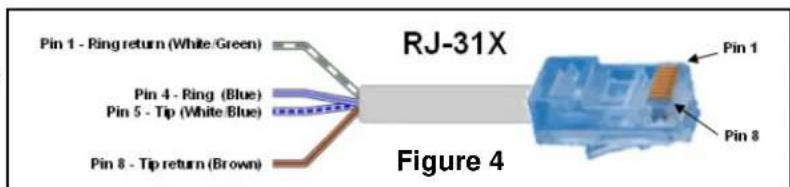
- Terminate a patch cable with a RJ45 on one end and bare-wire connection on the other (see Figure 4). Connect the bare-wire end of the patch cable to the security system according to manufacturer's instructions. Insert the RJ45 connector end of the cable into the RJ45 jack on the module that is labeled "LINE SEIZURE".
- Activate the Line Seizure function on the module by locating the two white dip switches on the module, peeling off the protective blue tape, and moving both switches upward to the active position (see Figure 5).