M55WS - Mikrofon Audix - Gratis bruksanvisning og manual
Finn enhetens veiledning gratis M55WS Audix i PDF-format.

Brukerspørsmål om M55WS Audix
0 spørsmål om dette apparatet. Svar på dem du kjenner, eller still ditt eget.
Still et nytt spørsmål om dette apparatet
Last ned instruksjonene for din Mikrofon i PDF-format gratis! Finn veiledningen din M55WS - Audix og ta den elektroniske enheten tilbake i hendene. På denne siden er alle dokumenter som er nødvendige for bruken av enheten din publisert. M55WS av merket Audix.
BRUKSANVISNING M55WS Audix
AUDIX.
PROFESSIONAL MICROPHONES
natural_image
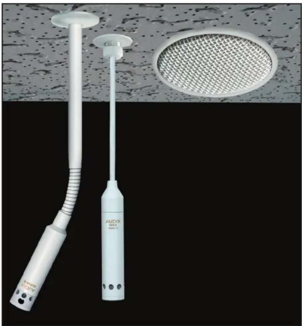
Two medical or industrial devices labeled 'AUDIX M50' and 'AudiX 2000' against a textured ceiling and meshed circular panel (no text or symbols on the devices themselves)AUDIX M55 INSTALLATION GUIDE
Thank you for choosing Audix! Our products are designed to provide you with many years of reliable service. Please read this manual before using the system for optimal installation and operation.
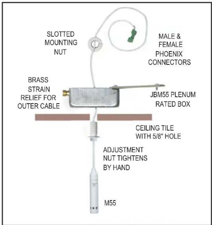
M55 JUNCTION BOX ASSEMBLY
natural_image
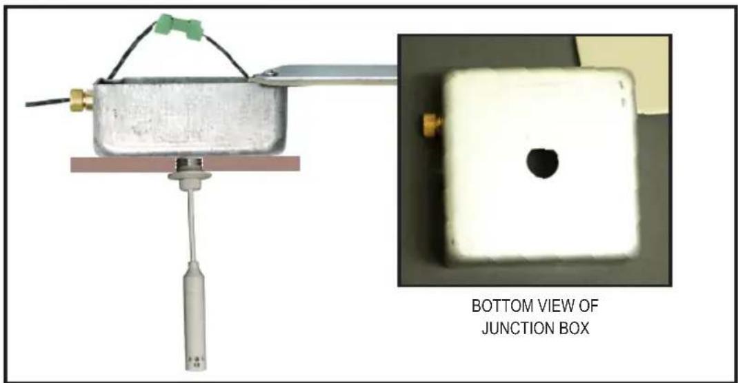
Experimental setup showing a mechanical component connected to a junction box, with an inset close-up of the same object (no text or symbols on main components)- DRILL 5/8 INCH HOLE IN THE CEILING TILE.
• OPEN JMB55 BOX LID AND PLACE BOX ON TOP OF 5/8 INCH HOLE IN THE CEILING TILE. (SEE #1) - INSERT M55 THREADED CEILING MOUNT THROUGH CEILING TILE AND INTO THE JBM55 BOX
• SECURELY TIGHTEN THE KNURLED NUT. (SEE #2) - INSERT PLENUM WIRE (BELDEN 9451P OR 82761 OR EQUIVALENT THROUGH STRAIN RELIEF (SEE #3) AND TERMINATE TO MATING PHOENIX CONNECTOR. (SEE #4 AND #5)
• TIGHTEN STRAIN RELIEF AND CLOSE LID OF JMB55 BOX. (SEE #5) - LOOSEN M55 KNURLED NUT, ADJUST CABLE TO APPROXIMATE DESIRED LENGTH, AND TIGHTEN NUT. (SEE #6)
• TIGHTEN THE PLENUM CABLE STRAIN RELIEF NUT AND ARRANGE EXCESS M55 WIRE IN BOX AND CLOSE LID.(SEE #7) - FINE ADJUSTMENTS TO MICROPHONE HEIGHT CAN BE MADE EASILY FROM BELOW CEILING BY LOOSENING THE M55 KNURLED NUT, LENGTHENING/SHORTENING WIRE AND RETIGHTENING KNURLED NUT. (SEE #8)
INSTALLATION AND WIRING INSTRUCTIONS FOR AUDIX M55 CEILING MICROPHONES
1
natural_image
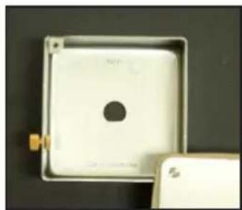
Close-up of a white square electronic component with a central hole, placed on a dark surface (no visible text or symbols)Open lid of JBM55 box and place on top of ceiling tile drilled hole.
2
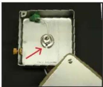
natural_image
Interior view of a small electronic device with a central component and a red arrow pointing to it, no visible text or symbols.Insert ceiling mount through ceiling tile hole, and into JBM55 box then tighten the knurled nut.
3
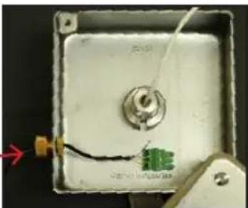
natural_image
Close-up of a small electronic device with wires and a central component, no visible text or symbolsInsert plenum wire through strain relief nut, then connect to the Phoenix terminal. Recommended cable: Belden 9451P - .124" O.D. or Belden 82761 - .116" O.D.
4
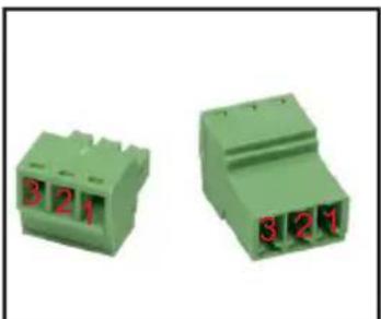
natural_image
Two green 321-pin electrical connectors with red pin labels (no text or symbols on body)Wiring:
1 = Ground
2 = Blue (+)
3 = Yellow (-)
5
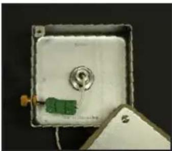
natural_image
Close-up of a white rectangular electronic device with a green component and a metallic knob, partially placed on a dark surface (no visible text or symbols)Connect Phoenix terminals.
6
natural_image
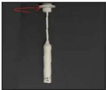
Close-up of a white cylindrical object with a red circular arrow indicating rotation (no text or symbols visible)Loosen M55 knurled nut (above), adjust cable to approximate desired length, and tighten nut.
7
natural_image
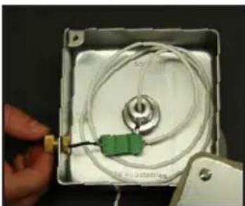
Close-up of a hand holding a small electronic device with a green connector and coiled cable inside a white square frame (no visible text or symbols)Tighten the strain relief nut. Arrange excess wire in box and close lid.
8
natural_image
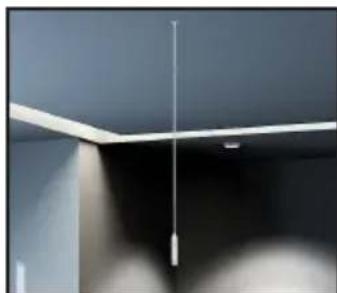
Close-up of a ceiling-mounted fixture with a vertical pole and horizontal beam (no text or symbols visible)For final adjustment, loosen knurled nut, adjust cable length, and tighten nut.
SEISMIC RESTRAINT INSTRUCTIONS
SEISMIC RESTRAINT DIAGRAM:
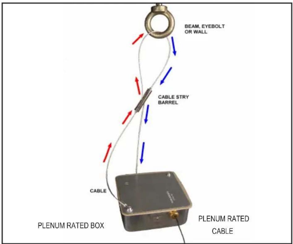
Wrap the cable through fastening point (beam,eyebolt). Next, slip the cable through the top of cable stay barrel pulling excess cable until taut.
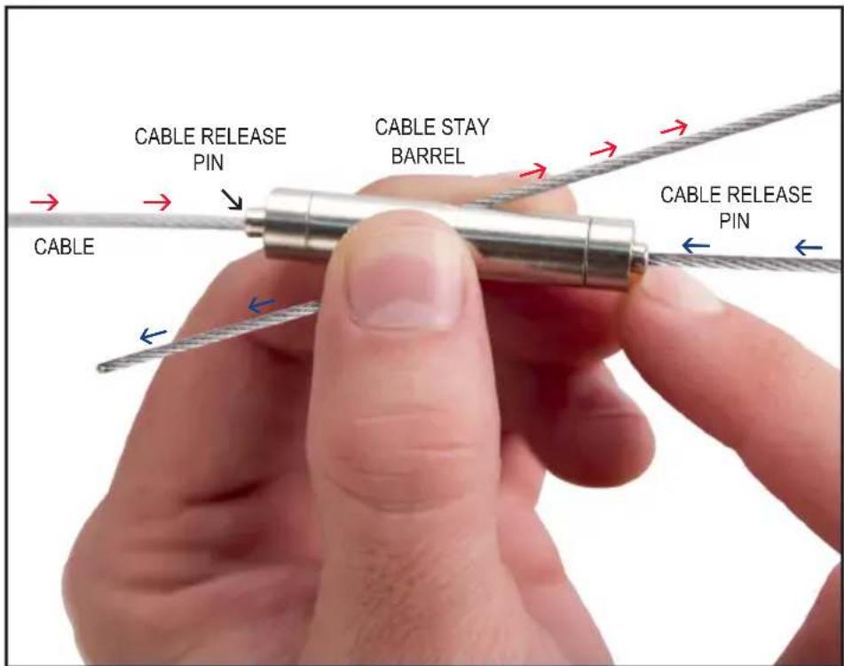
To loosen or disassemble cable, depress the cable release pin and pull cable to desired length.