Synergy Premiere KSP-C6 - Luidspreker KLIPSCH - Gratis gebruiksaanwijzing en handleiding
Vind de handleiding van het apparaat gratis Synergy Premiere KSP-C6 KLIPSCH in PDF-formaat.

Gebruikersvragen over Synergy Premiere KSP-C6 KLIPSCH
0 vraag over dit apparaat. Beantwoord die u kent of stel uw eigen vraag.
Stel een nieuwe vraag over dit apparaat
Download de handleiding voor uw Luidspreker in PDF-formaat gratis! Vind uw handleiding Synergy Premiere KSP-C6 - KLIPSCH en neem uw elektronisch apparaat weer in handen. Op deze pagina staan alle documenten die nodig zijn voor het gebruik van uw apparaat. Synergy Premiere KSP-C6 van het merk KLIPSCH.
GEBRUIKSAANWIJZING Synergy Premiere KSP-C6 KLIPSCH

Klipsch ^® INC.
AUDIO AND HOME THEATER PRODUCTS
KLIPSCH SYNERGY SERIES

text_image
PREMIÈRE™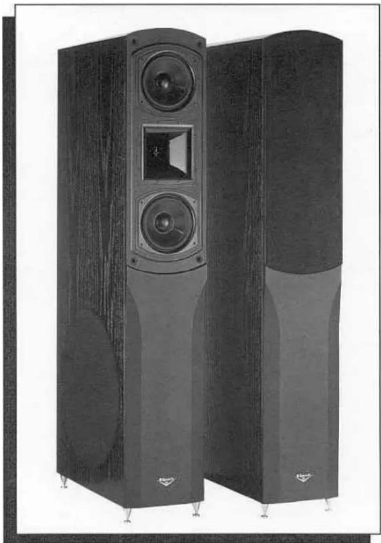
natural_image
Exterior view of two large outdoor speakers with visible sound dividers and speaker towers (no text or symbols)OWNER'S MANUAL & WARRANTY
KSP 400 ^TM , KSP-C6 ^TM , KSP-S6 ^TM

text_image
Klipsch® A LEGEND IN SOUND KLIPSCH SYNERGY SERIES PREMIÈREDear Klipsch Synergy Premiere™ Owner,
Congratulations on your purchase of Klipsch Synergy Premiere™ loudspeakers! You have selected one of the finest loudspeakers made, a tribute to over 50 years of engineering expertise and fine craftsmanship that make Klipsch "A Legend in Sound®." These products represent the state-of-the-art in loudspeaker design emphasizing a completely integrated approach for exceptional home theater performance.
The Klipsch Synergy Premiere Series was developed to create the finest home theater experience possible, with the “front row center” sound Klipsch is famous for. Our goal was to develop the best possible recreation of an actual movie theater environment from a sonic perspective, taking advantage of the many recent advances in digital technology for audio and video that make home theater closer and closer to the experience you enjoy at the local cinema. By placing a powered subwoofer in the base of each tower main speaker we have effectively placed two subwoofers in the room, all within the space requirements of two main speakers. This results in a system with tremendous dynamic range and remarkably life-like performance. The perfectly matched KSP-C6 center channel speaker and KSP-S6 dedicated matching rear surround speakers with Klipsch’s exclusive wide-dispersion surround technology™ complete the system, for a home theater that meets Klipsch’s demanding criteria for sonic performance. Traditional Klipsch efficiency and acoustic design integrity mean this full set of matched loudspeakers creates an all-encompassing sonic experience that will thrill and please you for many years.
Please take the time to fill out the enclosed questionnaire and warranty registration card. This information helps us serve you better and assists our dealers in meeting your needs as a valued Klipsch customer. Should you have any questions, or need more information on Synergy Premiere, or other Klipsch products, please contact us. We will be happy to assist you, and we welcome your feedback.
Thank you for choosing Klipsch loudspeakers.
Sincerely,
Jed S Keipsch
Fred S. Klipsch
Chairman & CEO
PLANNING YOUR KLIPSCH HOME ENTERTAINMENT SYSTEM
Your new Klipsch speakers will enhance the performance of your home entertainment system, whether they are used as an audio or home theater system. For optimum performance placement is a very important part of getting the most from your speakers. Please refer to the diagrams below as a general guide for how you should place your Synergy Premiere speakers.
KLIPSCH COMPLETE HOME THEATER™
Klipsch has long been a leader in the area of loudspeakers for home theater, building on its early development of custom sound systems for professional movie theaters. This technical expertise is put to use in developing the best truly integrated speaker systems for home theater system applications. While each Klipsch speaker must meet certain specific objective criteria on its own, it is the careful and deliberate design of all the speakers that results in the even and all-encompassing sound that separates an outstanding home theater system from a mediocre one. This means that a system's speakers should be voice-matched, or timbre matched, so that the resulting outputs have similar sonic characteristics. Thus, as sound information propagates through the listening room it delivers a seamless, enveloping experience, making the speakers and room environment seemingly disappear into the movie itself.
The demands of the latest source materials with true movie theater quality soundtracks and discrete multi-channel sound have made the significance of properly matching speaker systems of paramount importance. To duplicate all the effects that movie directors and sound engineers have built into today's movies, you need precise reproduction of the original signals, precise directional information and accurate dynamic detail. Klipsch design specifies that each of its speakers meet these criteria.
Audio

Front Left and Right Channels

Audio/Home Theater
Left and Right Surround Channels

Center Channel

Powered Subwoofer

text_image
Front Left and Right Channels Couch
flowchart
graph TD
    A["Front Left Speaker"] --> B["Video Shielded Center Channel"]
    C["Front Right Speaker"] --> B
    D["RS"] --> E["Left Rear Surround Channel"]
    F["RS"] --> G["Right Rear Surround Channel"]
    H["SW"] --> I["Optional Powered Subwoofer"]
    J["COUCH"] --> K["Image of the shielded center"]

natural_image
Exterior view of multiple electronic speakers with various speaker models (no visible text or labels)For truly complete home theater, Klipsch believes you need closely matched components that are capable of accurately reproducing the total range of human hearing. We firmly believe it is the careful integration of component loudspeakers in a home theater system that deliver optimal performance. Therefore Klipsch recommends the following grouping of components for a Klipsch Synergy Premiere Home Theater:
KSP 400 Front Mains (2) KSP-C6 Center Channel (1) KSP-S6 Rear Surrounds (2) **

text_image
KLIPSCH® COMPLETE F Front Channel C Center Channel RS Rear Surrounds SW Subwoofer HOME THEATERYour Klipsch dealer can advise and consult on other combinations that will be well-matched, but the system outlined above was designed and tested by Klipsch Engineering for the best possible home theater performance.
**For persons seeking even greater bass impact and low frequency sound effects from the rear channels of 5.1 channel (Dolby Digital® or DTS®) capable electronics, an optional rear channel subwoofer may be added to the above system. Consult your Klipsch dealer regarding this option.
Since the Synergy Premiere KSP models are designed for a variety of applications we will review each application by model.
KLIPSCH Synergy Premiere - KSP 400™ Main Speakers
The Klipsch Synergy Premiere KSP 400 Main speaker is a hybrid design using a passive 2-way high and mid-bass frequency section which is always driven with an external power amplifier, and an active subwoofer driven by an integrated internal power amplifier. The subwoofer section may be connected with either high (speaker) level amplifier outputs, or line level pre-amp outputs, but is always driven by its own internal power amplifier. The combination of the two sections in the single enclosure creates an essentially 3-way loudspeaker system. A sophisticated crossover network is used to send information below 80 Hertz to the subwoofer, below 3000 Hz to the dual mid-bass drivers and the information above 3000 Hz to the Tractrix® horn.
The three-way system uses two separate chambers within the enclosure. The upper portion houses the mid-bass and high frequency section, which uses a pair of 6.5-inch mid-bass woofers and Klipsch's exclusive fourth-generation Tractrix® horn in a d'Appolito configuration. The Tractrix® horn utilizes a 1-inch compression driver for easy and efficient reproduction of the high and midrange frequencies. This design provides exceptional stereo imaging and precise detail in the critical vocal ranges for sound that is as life-like as it gets. The lower portion, and much of the internal cabinet volume, is devoted to providing the necessary back air chamber for powerful low bass output from the built-in subwoofer. The bass section (subwoofer) utilizes a discrete output stage 200 watt amplifier (400 watts peak power) driving a side-firing 15-inch woofer. Bear in mind that each of the main speakers has the built-in 15-inch powered subwoofer for over 300 square inches of total effective radiating area. This is approximately 30% larger than a single 18-inch woofer!
Apart from their acoustic performance, these speakers set a new standard in cosmetic detail, fit and finish, and contemporary design in wood cabinet construction. Tall and narrow, the KSP 400 is less than nine inches wide but stands four feet tall. The height places the d'Appolito configuration at the optimal listening level to optimize the effectiveness of that driver configuration and the coverage pattern of the horn. Available in three fine wood finishes the KSP 400 is a stunning example of the Klipsch state-of-the-art in loudspeakers.
With high efficiency, low distortion, controlled directivity (controlled polar response) and flat frequency response, the KSP's deliver the sound Klipsch is famous for. Klipsch is confident you will be pleased with these speakers and the continued tradition of fine sounding Klipsch loudspeakers.
SPEAKER SUPPORTS - Crossbar Feet or Brass Spikes
Packed with your KSP 400 are two different sets of feet for speaker support. A pair of black crossbar feet (with 4 attachment screws) and 4 brass spike feet. Your KSP 400 has a footprint that is narrow when viewed from the front and wide when viewed from the side. This minimizes sonic reflections from the cabinet which improves the quality of stereo imaging and sound staging of the frontal high frequency drivers. The extra depth of the side panels permits the side mounting of a large subwoofer driver for powerful reproduction of bass frequencies, which are largely non-directional in nature.
Crossbar Feet
In situations that require an extra margin of side-to-side tip stability, we recommend use of the supplied crossbar feet. The presence of small children, large pets, or placement of the speaker in a high traffic area would be examples of such situations. These crossbar feet can be used on either hard or carpeted floors.
Installation of Crossbar Feet
- Lay the speaker on its side on a soft, padded surface (clean carpeted floor) with the side firing subwoofer facing up.
- Locate the 2 black crossbar feet and 4 pan head machine screws provided in the packing.
- With the aid of an assistant, lift the bottom end of the speaker off the floor. It can be propped up on a large bulky pillow or other soft support.
- Orient the crossbar feet so that the flat side with the nylon glides will face down when the speaker is standing upright. These feet are designed to go across the narrow dimension of the cabinet with one toward the front of the cabinet and the other toward the rear.
- Attach the feet with the supplied screws to the inboard set of threaded inserts on the cabinet bottom. The outboard set of threaded insert holes are used for the installation of the brass spike feet (see below).
- Snug the screws with a #2 Philips head screwdriver. DO NOT OVERTIGHTEN!
- With the aid of an assistant, carefully lift the speaker off of the floor and place it on its installed feet.
- Position the loudspeaker as discussed below.
- Repeat steps 1-8 for the other loudspeaker.
Brass Spike Supports - Mechanical Transfer Devices
If the speaker is placed in an area where it is unlikely to be tipped over, we recommend use of the brass spiked feet, which act as mechanical transfer devices. By concentrating the weight of the speaker on the spikes an improved mechanical connection to the floor (especially on carpeted floors) is achieved. This improves the definition, clarity and detail of the speakers musical reproduction by channeling cabinet vibration into the floor. They also provide an improvement in the speakers lateral stability on carpeted surfaces. The spikes are intended for use in carpeted rooms, but with care, can be used on hardwood, vinyl, or tile floors. Be advised that they will scratch or mar the floor surface. In either case, we recommend that the final speaker positions be determined before the spikes are installed. Mark the speakers' location on the floor with masking tape, install the spikes (as described below) and then reposition each speaker into the desired location. ONCE THE BRASS SPIKED FEET HAVE BEEN INSTALLED, DO NOT ATTEMPT TO MOVE OR TILT THE SPEAKER WITHOUT COMPLETELY LIFTING ALL FOUR SPIKED FEET OFF THE FLOOR! As the speaker is very heavy, enlist the aid of an assistant to move or reposition the speaker once it is placed on its supports.
Installation of Brass Spikes (mechanical transfer devices)
- Lay the speaker on its side on a soft, padded surface with the side firing subwoofer facing up.
- Locate the 4 brass spiked feet provided with your speaker.
- Screw the threaded portion of the spikes into the outboard set of threaded inserts in the bottom of the cabinet and gently snug them by hand. DO NOT OVERTIGHTEN them by using pliers or other tools as you may mar the finish of the brass spikes.
- With the aid of an assistant, carefully lift the speaker off the floor and set it on its installed feet in the predetermined location as discussed in the above application section.
- If the floor is uneven and the speaker rocks back and forth, the appropriate foot's height can be adjusted to compensate for this. We recommend that an assistant tilts and steadies the speaker while you make height adjustments to the spikes.
- Repeat the above procedure for the other loudspeaker.
HOW TO CONNECT Synergy Premiere MAIN SPEAKERS (KSP 400 models
Placement
-
Place the speakers in the front of your listening/viewing room with a separation between left and right speakers of not less than 6 feet, placed along the same wall and generally oriented toward the front of the room. For better quality stereo imaging, we recommend the speakers be angled, or toed in, toward the listener. Room acoustics vary, so we suggest some experimentation with specific placement within the room. The KSP 400 cabinets are mirror image with respect to the orientation of the subwoofer driver. They are labeled Left and Right (indicated by an L or R following the serial number). In most situations where the speakers will flank cabinetry (entertainment center), electronics and/or a television, orient the subwoofers to fire outward away from each other. However, there are circumstances where having each subwoofer fire inward at one another will deliver better performance. An example would be where there are no obstructions between the speakers, and they are widely spaced near sidewalls.
-
Unplug your Power Amplifier. Switch all of your electronics to the "OFF" position, including the power switches on the control panel of both KSP 400 speakers.
AC Power
Since your KSP 400's have an internal power amplifier to drive the subwoofer, arrangements must be made to plug each speaker into a nearby 110 volt AC wall outlet. A three-prong grounded outlet is recommended wherever possible, or a grounded power strip. Avoid extremely long extension cords of small gauge since they can reduce the amount of current available to the amplifier and be a potential fire hazard. A detachable power cord is supplied with each speaker. For safety reasons this cord and all other signal connections should be unplugged from the back panel of the speaker if it is being carried to a new location.
Speaker Wire Connections
When making any type of speaker wire connection be sure to observe the proper polarity when connecting the wires. Most speaker wire is color coded or has some distinguishing marking to differentiate the two conductors. Speaker wire connectors on most loudspeakers and amplifiers are also color coded. Typically, RED is positive (+) and BLACK is (-). Klipsch observes this practice and marks positive (+) in Red and negative (-), or ground, in Black. It does not matter which conductor of the speaker wire is connected to the positive or negative terminals of your equipment as long as you are consistent. Be sure that the connections from the amp to the speaker on all of the various channels of your system are connected in the same manner.
Make all connections with your equipment POWER - OFF and dress the exposed (bare) ends of the wire so they cannot make contact with each other (cause a short). If this should occur, your amplifier and loudspeakers may be damaged. If a pair of stereo speakers is out of phase (one speaker has the positive and negative terminals reversed) relative to each other, you will hear no center stereo image and a reduction in the amount of bass produced. To remedy this situation check all the connections to make sure BOTH speakers are connected to the amplifier in the same fashion with positive to positive and negative to negative. Refer to Figure A.
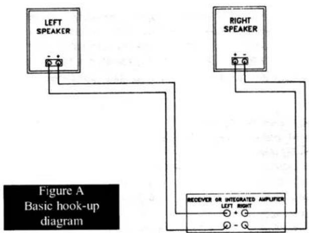
text_image
LEFT SPEAKER RIGHT SPEAKER Figure A Basic hook-up diagram RECEIVER OR INTEGRATED AMPLIFIER LEFT RIGHT + - Q - QThe simplest connection is to run a pair of speaker wires (one from each speaker) from the main LEFT and RIGHT channels of your amplifier to any one of the THREE pairs of five-way binding posts located on the control/input panel on the back of your KSP 400. The gold metal coupling straps that tie these three pairs of connectors together must remain in place for this type of connection. Refer to Figure B.
Improvements in clarity and detail can be achieved by Bi- or Tri-wiring your speakers. This involves removing some or all of the gold coupling straps from the binding posts on the back of the speaker and running separate bass and Mid / High frequency speaker wires from the same amplifier (consult your dealer for details regarding connection of multiple speaker cables to the speaker outputs of your specific amplifier). Refer to Figure C.
One common example of a bi-wire type of connection would be to remove the gold coupling straps between the High and Mid frequency binding posts (leaving the coupling straps in place between the mid and low frequency binding posts) and running separate speaker wires to the High and Mid connectors. A Tri-wire connection requires the removal of all gold coupling straps and running discrete speaker cables to the Low, Mid and High frequency speaker binding posts - separate connections for all THREE pairs of speaker binding posts.

Begin with the LEFT speaker. For the left main (front) loudspeaker, connect the wire from the BLACK(-) terminal to the electronics speaker output for the MAIN channel labeled: LEFT FRONT; LEFT MAIN; "A"; "Common"; "Ground"; "-" (negative); or colored BLACK.
Next connect the wire from the RED(+) left loudspeaker terminal to the electronics speaker output for the MAIN channel labeled: LEFT FRONT; LEFT MAIN; "A"; "8Ω"; "+"(positive) or colored RED. Most two conductor wire has some form of marking on the insulation to distinguish one conductor from the other. This can take the form of a stripe or ridge molded into the insulation or other distinguishing marks.
Move to the RIGHT speaker. For the right main (front) loudspeaker, connect the wire from the BLACK(-) terminal to the electronics speaker output for the MAIN channel labeled: RIGHT FRONT; RIGHT MAIN; "A"; "Common" "Ground"; "-" (negative); or colored BLACK.
- Next connect the wire from the RED(+) right loudspeaker terminal to the electronics speaker output for the MAIN channel labeled: RIGHT FRONT; RIGHT MAIN; "A"; "8Ω"; "+" (positive) or colored RED. Most two conductor wire has some form of marking on the insulation to distinguish one conductor from the other.
Line Level Connections - Subwoofer Section
The KSP 400 is also equipped with 2 line level inputs that drive the subwoofer only. They are labeled: Line In and LFE In. These would typically be used with home theater electronic components equipped with full bandwidth line level output jacks. These connections should be made using a shielded cable terminated with RCA phono plugs.
The Line In jack would be connected to a (non-filtered) full bandwidth subwoofer output of a four channel surround component. This signal should contain the normal bass information present in the main left and right channels.
The LFE jack is used only with the newer 5.1 (6 channel) surround sound systems (Dolby Digital® and DTS®). It is a discreet low frequency effects channel with different signal information than the bass frequencies present in all of the other channels. Since the information in this channel can be up to 10 decibels louder than the signal in the other channels, a separate LFE level control is provided to prevent it from overloading the subwoofer system. The LFE input and Line input are summed together so both connections may be used at the same time if your electronics provide you with both outputs. The LFE In must NOT be your only subwoofer connection.
A combination of speaker level and line level connections can also be used. For example, if you are connecting your KSP 400's to the electronics possessing all of the outputs mentioned above, you could first remove all of the speaker wire coupling straps from the binding posts on the control / input panel on the rear of each speaker. You could then use a Bi-wire connection to feed the High and Mid frequency speaker terminals on the KSP 400 and connect the Line In (and LFE In if available) to feed the subwoofer. A single wire variation of this type of connection can be done by leaving the coupling straps in place between the High and Mid speaker binding posts and using a single speaker cable to drive the mid / high frequency section of your KSP 400 (shown in Figure C). The line level connections to the subwoofer would remain the same.

CAUTION: DO NOT USE LINE LEVEL INPUTS AND SPEAKER LEVEL (Low In) INPUTS SIMULTANEOUSLY!
KSP 400 - Operating Controls and Settings - refer to Figure D - Control Panel
Power Switch
Located on the rear control panel of the KSP 400, the POWER switch turns the subwoofer ON and OFF. The KSP 400 should be unplugged and in the "OFF" position during the installation and connection procedure. When the switch is in the "AUTO" position the KSP 400 subwoofer section turns itself ON when it receives a signal from your system. If no signal is sent to the sub for a period of 15 to 20 minutes, the subwoofer section will turn itself off, (standby mode). For normal use it is recommended that the switch be left in the AUTO position. A Green light indicates the "stand by" mode in which the subwoofer's built-in amplifier will go "ON" when it senses a signal. A Red light indicates the subwoofer is "ON" receiving a signal and operating normally. No lights showing indicates power (current) is not reaching the amplifier. Please refer to the Troubleshooting section in this manual.

text_image
A LEGEND IN SOUND Klipschi Sub Level Line in LFE In LFE Level Bass Boost Power On Auto Off Speaker Level inputs + - Low In Mid In Hi In 120 VAC 240 WATTS 80 Hz WARNING: TO AVOID THE RISK OF FIRE OR ELECTRIC SHOCK, DO NOT EXPOSE THIS EQUIPMENT TO RAIN OR MOUSTURE. CAUTION: TO REDUCE THE RISK OF ELECTRIC SHOCK, DO NOT REMOVE COVER (OR BACK). NO USER SERVICEABLE PARTS INSIDE. REFER SERVICING TO QUALIFIED SERVICE PERSONNEL. 110008 AVIS BIOSIE DE CHOC ELECTRIOQUE → RE PAS QIVER →Figure D Control Panel
Sub Level
Sub Level is the master volume control for the subwoofer section of the KSP 400. This control knob adjusts the volume level of the subwoofer relative to the mid-bass and high frequency drivers. This allows the user to vary the amount of bass output to compensate for variations in room acoustics and personal taste. This control also affects the signals that are connected to the Line In jack, the LFE jack and the Low In (speaker level) binding post. This control does not affect the volume level of the mid-bass and high frequency section of the KSP 400.
Suggested control position for initial set-up: 10 o'clock


CAUTION: Avoid extreme clockwise (higher) adjustment of this control to prevent overdriving and damaging the amplifier and its 15-inch woofer.
LFE Level
The LFE Level control adjusts the volume of the Low Frequency Effects signal from a 5.1 (6 channel) system, independent of the main Sub Level control. This control only affects the signals connected to the LFE In jack. These signals are mixed with the bass signals that are controlled by the Sub Level control. It is important to note that LFE signals can be up to 10 decibels louder (a ten fold increase in required amplifier power) than the main bass signals. This control provides a means to regulate the LFE volume level so that it does not overdrive the subwoofer system.
Suggested control position for initial set-up: 8 o'clock


CAUTION: Avoid extreme clockwise (higher) adjustment of this control to prevent overdriving and damaging the amplifier and its 15-inch woofer. LFE signals contain extreme low frequency information.
Bass Boost Control
This control is similar to a tone control. Bass Boost provides an emphasis (boost) or de-emphasis (reduction) in the bass response centered at 30 Hertz. This allows the user to further refine the tuning of bass reproduction apart from just the output volume (Sub Level control). An appropriate setting will be determined by room acoustics and personal taste after experimentation with various settings. Full counterclockwise rotation of this control provides a -6 dB reduction in level centered at a frequency of 30 Hz. Full clockwise rotation of this control provides a +6 dB boost in level centered at a frequency of 30 Hz. If this control is left in its full clockwise position (maximum boost) this will give you a greater quantity of bass, but will reduce the maximum output capability of the subwoofer system.
Suggested control position for initial set-up: 12 o'clock

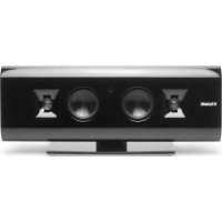
KLIPSCH Synergy Premiere - KSP-C6 - Center Channel Loudspeaker
The Synergy Premiere KSP-C6 is optimized for use as a center channel speaker. As such, it uses full magnetic shielding on all its drivers to provide video shielding and therefore minimizes picture discoloration or deformation due to stray magnetic fields. This model has four inserts, at the bottom of the speaker cabinet, for use with two "feet" (threaded rod with a jam nut) to adjust the tilt angle of the speaker so that it can be aimed directly at the listening location. A proper center channel speaker location should be on or as close to the video screen(TV) as possible, since these sounds are intended to appear as coming directly from the screen. A key example is the dialogue between people in a motion picture. To use a center channel speaker, your receiver or signal processor must have a designated center channel output.
HOW TO CONNECT KSP-C6 CENTER CHANNEL SPEAKER
Good cable and connections will make an audible improvement in the sound of your speakers. Consult your dealer for their recommendation.
Position the speaker as close to the television screen as possible and centered above or below the screen. Your KSP-C6 center speaker incorporates design features to direct the sound toward the listener when you are seated in front of your video display.
The KSP-C6 is supplied with two adjustable "feet" to angle the speaker either up or down, depending on placement. Use the adjustable feet to aim the speaker directly at the listening height. If the KSP-C6 does not need to be angled, attach the four stick-on rubber pads supplied over all four threaded cabinet inserts. (see figure #2 on the Accessory Pack page) Either Feet or Pads must be used to achieve proper acoustic performance.
For LOW placement (see figure #3 on the Accessory Pack page): Angle the KSP-C6 upward by screwing the two threaded rods into the threaded inserts at the front bottom edge of the cabinet.
For HIGH placement (see figure #3 on the Accessory Pack page): Angle the KSP-C6 downward by screwing the two threaded rods into the threaded inserts at the rear bottom edge of the cabinet.
To insert threaded rods:
A. Screw the threaded rods (pointed end into the cabinet) into the threaded inserts as described above. Use a small flat bladed screwdriver if necessary.
B. Thread the jam nut onto the threaded rod.
C. Adjust the length of the rods for proper angle. Imagine that the speaker is a spotlight and you are aiming the beam at the listening area.
D. Gently tighten the jam nut to secure the rod. DO NOT OVERTIGHTEN!
E. Cover the exposed rod ends with the small vinyl caps to prevent marring of your television cabinet or shelf.
F. Cover the remaining threaded cabinet inserts with two of the stick-on rubber feet. (see figure #3 on Accessory Pack page)
Switch electronics to "OFF" position.
From the center loudspeaker, connect the wire from the BLACK(-) terminal to the electronics speaker output for the CENTER channel labeled "common", "ground", "-" (negative) or colored BLACK.
Next connect the wire from the RED(+) loudspeaker terminal to the electronics speaker output terminal for the CENTER channel labeled "8Ω", "+" (positive), or colored RED. Most two conductor wire has some form of marking on the insulation to distinguish one conductor from the other. This can take the form of a stripe or ridge molded into the insulation or other distinguishing marks.
Your Klipsch dealer can help you with the selection of proper high quality cable to ensure optimal connections and ease of use.
KLIPSCH Synergy Premiere - KSP-S6 Dedicated Surround Speaker
Klipsch's dedicated surrounds are intended for use as surround sound speakers, designed as rear or side surrounds in home theater applications, or a multi-channel audio video system. They are NOT intended for use as main or front speakers (left, center, or right speaker). They work in combination with other speakers, adding dynamic realism and special effects impact by virtue of their high efficiency, making the most of the lower current outputs common with surround channels on many electronic components. These speakers have a high sensitivity level (a measure of efficiency), resulting in high acoustic output (loudness) in surround applications. A 3 dB increase in sensitivity is equivalent to DOUBLING the amount of amplifier power needed to achieve the same loudness (volume output)! They feature Klipsch's exclusive Wide-Dispersion Surround Technology™, which utilizes an array of drivers to create a uniform 180° sound field through the use of two horn tweeters aligned at 90° to one another. The resulting widely dispersed sound field is perfectly suited for rear channel surround applications. This unique Klipsch approach provides both good ambient sound and directional information, making Klipsch surrounds ideal for the latest multi-channel Dolby Digital® (AC-3) soundtracks on DVD and laser disc formats, making Klipsch "Digital Ready."
HOW TO CONNECT KLIPSCH KSP-S6 SURROUND SPEAKERS
Good cables and connections will make an audible improvement in the sound of your surround speakers. Your dealer can assist you in selecting cables that best meet your needs, including many designed specifically for surround speakers which are easily hidden or offer cleaner appearance.
Surround Speaker Placement - One of the principal advantages of Klipsch's unique Wide-Dispersion Surround Technology™ is greater placement flexibility. Due to the full 180° sound field you can place these speakers on rear walls, side walls and even the ceiling if necessary. The most common placement for most home theater rooms is either on the side walls, adjacent to the listening/viewing position, or on the rear walls toward the corners of the room, with vertical placement approximately 5 to 7 feet from floor level, as measured from the base of the speaker.
An alternative placement would be on the ceiling above the listening position either directly overhead or several feet behind. In a ceiling installation the speaker can be oriented with drivers facing either the front/rear in the room, or facing the side walls to compensate for room shape or layout. Because of this we recommend experimenting with speaker placement until you achieve the balance and directional cues you want.
HOW TO MOUNT KLIPSCH KSP-S6 SURROUND SPEAKERS
Mounting your Klipsch wide-dispersion surround speaker to a wall can be accomplished by using the supplied keyhole brackets on the rear of the cabinet. These two brackets are vertically oriented for attachment to a pair of wood screws secured into wood wall studs.
A. Install 4 rubber stick-on bumpers (one on each corner of the rear panel of the speaker) to provide clearance between the wall and the cabinet for the speaker wire. This will also prevent the speaker from marring the wall.
B. Mark mounting screw locations on the wall using the supplied paper template on the inside back cover of the owner's manual. If the template is not available, then space the mounting screw locations 7 and 9/16 inches apart on a vehicle line. We recommend checking the vertical orientation of the marked hole locations on the wall by aligning them with a torpedo level.
C. Be sure to allow at least a 4-inch clearance above the top screw location. This is to accommodate the 3 1/2-inch cabinet dimension above this screw and the 1/2-inch vertical slide needed to hook the bracket on the screw head.
D. The use of a #10 or #12 (2.5" - 3" long) pan head wood screw is recommended for mounting into a wood stud.
E. Check the fit of the screw head in the keyhole fitting before installation as screw head sizes do vary.
F. Drill the proper size pilot hole, for the screw selected, at the marked positions on the wall and install the screws into the wall stud. Leave the back surface on the screw head protruding about 1/4-inch from the wall surface. This facilitates hooking the keyhole bracket over the screw head. Adjustment of the clearance between the wall and the screw head may be necessary to achieve a proper fit. If a stud is not available, use the appropriate type of drywall or masonry anchor that will support the weight of the loudspeaker with a generous safety margin. Please consult your dealer, custom installer or a building contractor in these situations.

CAUTION: DO NOT USE THE KEYHOLE BRACKETS FOR CEILING MOUNTING! Consult your dealer, custom installer or contractor for alternate mounting methods or refer to the following section.
Optimal surround speaker placement is highly dependent upon individual room layout and the resulting acoustics. Consult your Klipsch dealer for guidance on placement to suit your particular home theater room.
- Switch electronics to "OFF" position. Your Klipsch surround speaker should be connected to the speaker level connections labeled SURROUND or REAR channel on your A/V receiver or multi-channel amplifier. Maintaining consistent polarity (+) and (-) on both LEFT and RIGHT sides is important to safe and proper operation of your sound system.
Make sure when connecting to a Dolby Digital® (AC-3) system that the correct REAR channel speaker wire is connected to the proper sides, LEFT and RIGHT, when you are seated in the listening position.
-
For the LEFT rear surround loudspeaker, connect the wire from the BLACK(-) speaker terminal to the electronics speaker output terminal labeled REAR LEFT or LEFT SURROUND channel, or marked “-”, or colored BLACK. Next connect the wire from the RED(+) loudspeaker terminal to the electronics speaker output terminal labeled REAR LEFT or LEFT SURROUND channel, or marked “+”, “8Ω”, or colored RED. Most two conductor wire has some form of marking on the insulation to distinguish one conductor from the other. This can take the form of a stripe or ridge molded into the insulation or other distinguishing marks.
-
For the RIGHT rear surround loudspeaker, connect the wire from the BLACK(-) speaker terminal to the electronics speaker output terminal labeled REAR RIGHT or RIGHT SURROUND channel, or marked “-”, or colored BLACK. Next connect the wire from the RED(+) loudspeaker terminal to the electronics speaker output terminal labeled REAR RIGHT or RIGHT SURROUND channel, or marked “+”, “8Ω”, or colored RED. Most two conductor wire has some form of marking on the insulation to distinguish one conductor from the other. This can take the form of a stripe or ridge molded into the insulation or other distinguishing marks.
-
The surround speakers should be placed as indicated in the diagram for home theater set-up. Surrounds are used to create directional effects, adding to the feeling that you are "part of the action" when watching a movie, and while Klipsch's exclusive wide-dispersion surround technology™ relaxes placement issues, good placement is still important for achieving optimum benefits of surround sound.
TROUBLESHOOTING Your KSP 400 Speakers
If one or both KSP 400 subwoofers has (have) no output:
Double check your power (AC) and system connections.
- Make sure the Power Switch on the rear control panels of both units is set to the "ON" or "AUTO" position.
- Make sure the subwoofer level control on each unit is turned up.
- Check the LED light located on the control panel. GREEN indicates "stand by" mode in which the amplifier will go "On" when it senses a signal. RED indicates "On" and receiving a signal. If the LED is not lit, unplug the subwoofer and change the AC fuse. Be sure to replace the fuse with an identical value. The fuse value is printed on the control panel.
- The KSP 400 subwoofer power amplifier is protected by a thermal sensor. If the unit is run for extended periods beyond its designed power rating, the thermal sensor will activate and engage to shut down the subwoofer. If this occurs, turn OFF the Power Switch, reduce the volume and wait five minutes before restarting the system.
- Check the cable input connections for a reversal of one of the speaker cables coming from the amplifier and correct if necessary. Incorrect polarity will result in diminished low frequency output when both loudspeakers are operating.
- If you experience a noticeable hum when the subwoofer section is connected to your system, try installing a 3-to-2 prong AC adapter (supplied) on the power cord to the subwoofer. If you are still experiencing difficulties or problems, consult your authorized Klipsch dealer.
Klipsch Limited Warranty
Klipsch Inc
KLIPSCH, INC., ("KLIPSCH") warrants this product to be free from defects in materials and workmanship (subject to the terms set forth below). For a period of five (5) years from the date of purchase, KLIPSCH will repair or replace (at KLIPSCH's option) this product or any defective parts (excluding electronics and amplifiers) in this product. For products that have electronics or amplifiers, the warranty on those parts is for a period of two (2) years from the date of purchase.
To obtain warranty service, please contact the KLIPSCH authorized dealer from whom you purchased this product. If your dealer is not equipped to perform the repair of your KLIPSCH product, it can be returned, freight prepaid, to KLIPSCH INC., for repair. Please call KLIPSCH at 1-800-KLIPSCH for instructions. You will need to ship this product in either its original packaging or packaging affording an equal degree of protection.
Proof of purchase in the form of a bill of sale or receipted invoice which is evidence that this product is within the warranty period must be presented to obtain warranty service.
This Warranty is invalid if (a) the factory applied serial number has been altered or removed from this product or (b) this product was not purchased from a KLIPSCH authorized dealer. You may call 1-800-KLIPSCH to confirm that you have an unaltered serial number and/or you purchased from a KLIPSCH authorized dealer.
This Warranty does not cover cosmetic damage or damage due to acts of God, accident, misuse, abuse, negligence, commercial use, or modification of, or to any part of the product. This Warranty does not cover damage due to improper operation, maintenance or installation, or attempted repair by anyone other than KLIPSCH or a KLIPSCH dealer which is authorized to do KLIPSCH warranty work. Any unauthorized repairs will void this warranty. This Warranty does not cover products sold AS IS or WITH ALL FAULTS.
REPAIR OR REPLACEMENT AS PROVIDED UNDER THIS WARRANTY IS THE EXCLUSIVE REMEDY OF THE CONSUMER. KLIPSCH SHALL NOT BE LIABLE FOR ANY INCIDENTAL OR CONSEQUENTIAL DAMAGES FOR BREACH OF ANY EXPRESS OR IMPLIED WARRANTY ON THIS PRODUCT. EXCEPT TO THE EXTENT PROHIBITED BY LAW, THIS WARRANTY IS EXCLUSIVE AND IN LIEU OF ALL OTHER EXPRESS AND IMPLIED WARRANTIES WHATSOEVER, INCLUDING BUT NOT LIMITED TO THE WARRANTY OF MERCHANTABILITY AND FITNESS FOR A PARTICULAR PURPOSE.
Some states do not allow the exclusion or limitation of incidental or consequential damages, or implied warranties, so the above exclusions may not apply to you. This Warranty gives you specific legal rights, and you may have other rights which vary from state to state.
Please complete the enclosed warranty card and mail it to Klipsch, Inc., P.O. Box 688, Hope, Arkansas, 71802.
PREMIÈRE
KSP-400TM
FRONT MAIN
| FREQUENCY RESPONSE: | 27 Hz - 20 kHz ± 3 dB |
| SENSITIVITY: | 95 dB @ 1 watt/1 meter |
| MAXIMUM OUTPUT: | 117 dB (SPL) |
| NOMINAL IMPEDANCE: | 8 Ω-ohms |
| CROSSOVER FREQUENCY: | 3 kHz/80 Hz |
| POWER HANDLING: | 200 watts maximum continuous (800 watts peak) |
| ENCLOSURE TYPE: | Sealed Enclosure |
| DRIVE COMPONENTS: | Three-way system using:One 1-inch (2.54 cm) K-97-KVcompression driver with a 90° x 60° Tractrix Horn®, and Two, 6.5-inch (16.51 cm) K-1057-KB mid-bass woofers; and One, 15-inch K-1060-K subwoofer |
| SUBWOOFER AMPLIFIER: | 200 watts continuous; discrete, high-current output devices; 400 watts dynamic power; dedicated LFE input |
| DIMENSIONS: | |
| WEIGHT | 115 pounds (52.21kg) |
| HEIGHT: | 48 inches (122 cm) |
| WIDTH: | 8.75 inches (22.23 cm) |
| DEPTH: | 19.75 inches (50.17 cm) |
| FINISH: | Medium Oak, Black Satin OrWest African Mahogany Wood Veneer Finish |
PREMIÈRE
KSP-S6TM
REAR SURROUND
| FREQUENCY RESPONSE: | 60 Hz - 20 kHz ± 3 dB |
| SENSITIVITY: | 94 dB @ 1 watt/1 meter (equivalent sound energy) |
| NOMINAL IMPEDANCE: | 8 Ω-ohms |
| CROSSOVER FREQUENCY: | 2800 Hz |
| POWER HANDLING: | 150 watts maximum continuous (600 watts peak) |
| ENCLOSURE TYPE: | Sealed Enclosure |
| DRIVE COMPONENTS: | Two-way system using:Two, 1-inch (2.54 cm) K-96-Sneodymium compression drivers with 90° x 60°Tractrix Horns®; and Two, 6.5-inch (16.51 cm)K-1057-K woofers |
| DIMENSIONS: | |
| WEIGHT: | 24 pounds (10.89 kg) |
| HEIGHT | 15.13 inches (38.43 cm) |
| WIDTH: | 13.38 inches (33.99 cm) |
| DEPTH: | 7.38 inches (18.75 cm) |
| FINISH: | Black Or White Vinyl-Matte Finish |
PREMIÈRE
KSP-C6™
CENTER
| FREQUENCY RESPONSE: | 63 Hz - 20 kHz ± 3dB |
| SENSITIVITY: | 94 dB @ 1 watt/1 meter |
| NOMINAL IMPEDANCE: | 8 Ω-ohms |
| CROSSOVER FREQUENCY: | 3000 Hz |
| POWER HANDLING: | 150 watts maximum continuous (600 watts peak) |
| ENCLOSURE TYPE: | Sealed Enclosure |
| DRIVE COMPONENTS: | Two-way system using:One, 1-inch (2.54 cm) K-97-KV magnetically shielded tweeter with a 90° x 60° Tractrix Horn®;and Two, 6.5-inch (16.51 cm) K-1057-KVmagnetically shielded woofers |
| DIMENSIONS: | |
| WEIGHT: | 28 pounds (12.70 kg) |
| HEIGHT: | 8 inches (20.32 cm) |
| WIDTH: | 23.42 inches (59.49 cm) |
| DEPTH: | 7.75 inches (19.69 cm) |
| FINISH: | Black Vinyl - Matte Finish |
For your records:
Model
Serial Number
Date Purchased
Dealer Name
Make sure you return your warranty card so that we may keep you up-to-date on new Klipsch products and promotions. As always, if you have any questions, contact your local authorized Klipsch dealer.
# 193084 KSP Manual
Kipscch, Inc. 8900 Keystone Crossing, Suite 1220 Indianapolis, Indiana U.S.A. 46240
Here
Postage Stamp
Place First Class