MSK-1SM-T - Nekategorizēts SolidDrive - Bezmaksas lietošanas instrukcija
Atrodiet ierīces rokasgrāmatu bez maksas MSK-1SM-T SolidDrive PDF formātā.

Lietotāju jautājumi par MSK-1SM-T SolidDrive
0 jautājums par šo ierīci. Atbildiet uz tām, ko zināt, vai uzdodiet savu.
Uzdot jaunu jautājumu par šo ierīci
Lejupielādējiet instrukcijas savam Nekategorizēts PDF formātā bez maksas! Atrodiet savu rokasgrāmatu MSK-1SM-T - SolidDrive un atgūstiet kontroli pār savu elektronisko ierīci. Šajā lapā ir publicēti visi dokumenti, kas nepieciešami jūsu ierīces lietošanai. MSK-1SM-T zīmola SolidDrive.
LIETOŠANAS INSTRUKCIJA MSK-1SM-T SolidDrive

natural_image
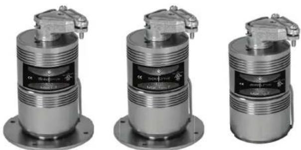
Three identical metallic industrial sensor or regulator components with threaded leads and mounting flanges (no visible text or symbols)SolidDrive MSK-1-T/MSK-1SM-T/MSK-1G-T Specifications
| Type | Full Range Transducer |
| Frequency Response(Hz) | 70 Hz to 15 kHz |
| Recommended Amplifier Power | 10 Watts |
| MSK-1-T & MSK-1sm-T Dimensions | 2.28'' Diameter x 4.8'' HeightMounting Foot 3.5'' Diameter |
| MSK-1g-T Dimensions | 2.28'' Diameter x 4.8'' HeightMounting Foot 2.0'' Diameter |
| Weight | 1.5 lb / .68 kg |
| UL Listing | 1480 & 2043 Pending |
NOTE: When installed in Canada, this product must be installed in accordance with the Canadian Electrical Code, C22.1, Part1.
natural_image
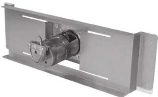
Metal mechanical component with threaded shaft and mounting bracket (no visible text or symbols)SolidDrive MSK-1-T In-Wall and In-Ceiling (Required for Drywall Mounting) Mounting Bracket Specifications
| Type | Patented balanced cantilever spring bracket |
| Construction | Heavy duty, galvanized steel |
| Dimensions | 120C - 2.0" H x 17.5" W x 5.0" D160C - 2.0" H x 25.5" W x 5.0" D240C - 2.0" H x 13.5" W x 5.0" D |
| Weight | 1.0 lb / .45 kg |
WARRANTY
SolidDrives are guaranteed for 7 years from date of purchase. Any misuses or modifications to this equipment in any way will void the warranty.
WARNING
Read instructions prior to operating. To reduce the risk of fire or electric shock, do not expose this product to rain or moisture. Unplug prior to cleaning and clean with a damp cloth. There are no user-serviceable parts in this product, please refer all servicing to qualified personnel.
SolidDrive
INSTALLATION & USE GUIDE
for MSK-1-T, MSK-1sm-T & MSK-1g-T Sound Masking Transducer
Experience Audio Perfection
Induction Dynamics extensive line of audio products makes it easy to create the ultimate audio system, regardless of installation requirements. Induction Dynamics builds these products with only the most select components and materials; and utilizes numerous unique and proven technologies.
INSTALLATION OF SOLIDDRIVE MSK-1-T INTO WALLS AND CEILINGS
By utilizing these basic installation steps, you can install the SolidDrive MSK-1-T into walls and ceilings for a variety of sound masking applications.
GETTING STARTED WITH SOLIDDRIVE
What's included with the SolidDrive MSK-1-T for installation into walls and ceilings and what is supplied by the installer —
A SolidDrive MSK-1-T consists of: One (1) SolidDrive MSK-1-T unit with included 10W transformer, supplied with 4 hard wire leads and one duplex conduit connector. *Additional mounting materials may need to be ordered with the SolidDrive MSK-1-T or supplied by the installer depending on the application.
For drywall: For in-wall and in-ceiling installation, you will have ordered one (1) or more SolidDrive MSK-1-T's and one (1) or more patented acoustic in-wall mounting brackets (one (1) bracket per MSK-1-T), which comes with four (4) #8-32 x 5/16" Phillips flat head machine screws for mounting the drive to the bracket. At the time of the order, you will also have specified mounting bracket(s) in widths of 120C, 160C, or 240C (ON CENTER of wall studs or ceiling joists) for proper width. *Installation also requires four (4) 1 3/8" drywall screws and one (1) container of 3M® Super 77 Spray Adhesive (supplied by the installer).
EXISTING DRYWALL INSTALLATION NOTE:
For retrofitting the SolidDrive MSK-1-T into existing drywall installations, it will be necessary to remove a portion of the existing drywall before installation and to replace the drywall after the SolidDrive MSK-1-T is installed. Please refer to the instructions marked with EXISTING DRYWALL for the steps necessary for the type of installation. If installing the SolidDrive MSK-1-T in new construction, IGNORE the EXISTING DRYWALL steps.
STEP 1
INSTALLATION INTO EXISTING DRYWALL
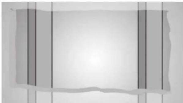
For installing the SolidDrive MSK-1-T mounting bracket into existing drywall, first cut a rectangular opening in the drywall. The minimum recommended opening size is approximately fifteen inches tall and beyond the width of the adjacent wall studs. This will help in attaching the mounting bracket, feathering the drywall back in, and getting the drywall to meet at the seams (Figure 1). This will allow proper distribution of sound and the SolidDrive MSK-1-T will function with optimum performance.
natural_image
Abstract grayscale image with vertical black lines on a light background, no text or symbols present.Figure 1 Cut an opening large enough to install the mounting bracket to the wall studs
STEP2
Attach the SolidDrive mounting bracket to wall studs or ceiling joists
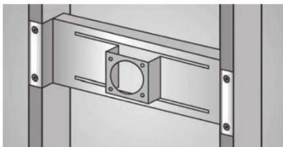
Place the mounting bracket between the wall studs or ceiling joists and secure with four 1 3/8" drywall screws. Insert the screws through the four pre-drilled holes in each flange and screw them into the face of each wall stud or ceiling joist (Figure 2). The drywall screws need to be driven flush with the surface of the flange so that the drywall sets flush on the bracket flange.
natural_image
Technical diagram of a mechanical assembly with mounting flanges and a central square component (no text or symbols)Figure 2
SolidDrive
MSK-1-T
mounting
bracket
attached to
the wall studs
STEP3
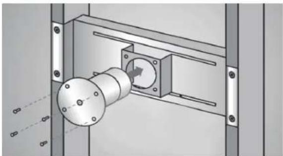
Insert the SolidDrive into the bracket
Feed the SolidDrive MSK-1-T cable through the round opening in the face of the mounting bracket. Insert the SolidDrive MSK-1-T through the same opening with the oversized mounting base facing outward toward the side that the drywall will be installed and flush against the bracket face. Align the pre-drilled holes in the mounting base to the threaded holes in the bracket face (Figure 3). Attach the SolidDrive MSK-1-T securely to the mounting bracket using the 4 Phillips flat head machine screws.
natural_image
Mechanical assembly diagram showing a rotating shaft mounted on a housing with mounting brackets (no text or symbols visible)Figure 3
SolidDrive
MSK-1-T
being installed
into the
mounting
bracket
STEP4
Electrical connections
Make the electrical connection between the SolidDrive MSK-1-T and the speaker cable using the desired transformer setting. NOTE: When installed in Canada, this product must be installed in accordance with the Canadian Electrical Code, C22.1, Part1.
10W: 5 wire input

Figure 4 Transformer connections
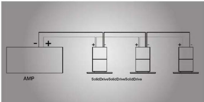
Connecting Multiple SolidDrives
Connect the amplifier (−) terminal to all Black (COM) wires for all SolidDrives in the system. Connect the amplifier (+) terminal to the colored wire that corresponds to the desired power tap for each SolidDrive in the system. Trim off the exposed bare wire on all unused wires and ensure that they cannot short to each other. Failure to do so may result in misoperation and place an unexpected load on the amplifier.
STEP5
Apply adhesive to the drywall surface and base of the SolidDrive
If possible, position the drywall panel so that the SolidDrive MSK-1-T is at the center of the panel or as far from the edge of the panel as possible. This will allow proper distribution of sound and the SolidDrive MSK-1-T will function with optimum performance. Prior to mounting, take measurements of the new drywall panel to determine the exact area that will come in contact with the base of the SolidDrive MSK-1-T and spray that area liberally with the 3M ^® Super 77 contact spray adhesive. Also, liberally spray the surface of the oversized mounting base of the SolidDrive MSK-1-T (masking around the base is highly recommended to prevent overspray). NOTE: Failure to apply the adhesive to both the drywall surface and oversized mounting base will prevent the system from functioning properly.
STEP6
EXISTING DRYWALL
Re-install rectangular cutout in wall
For re-installing the rectangle drywall panel that was cut out to install the SolidDrive MSK-1-T, it is important to create a uniform seal between the cut drywall and the existing drywall. This will allow proper distribution of sound and the SolidDrive MSK-1-T will function with optimum performance. Apply fast setting joint compound, not vinyl based, in the space between the cutout section and the existing drywall panel. Make sure to fill the space completely with drywall compound then proceed with the normal taping, sanding and finishing routine.
STEP7
Install the new drywall
Immediately install the new drywall before the spray adhesive sets up (approximately 10 minutes). This allows adjustment of the panel before the final location is determined. The drywall panel is to be fitted to the wall studs or ceiling joists and screwed into position. Apply joint compound in the space between the drywall panels and proceed with the normal taping, sanding and finishing routine. The joint compound filled between the panels will improve the distribution of sound as well as overall sound quality.
INSTALLATION OF SOLIDDRIVE MSK-1sm-T TO WOOD SURFACES
By utilizing these basic installation steps, you can install the SolidDrive MSK-1sm-T on wood, laminate, composites, and other porous surfaces. The MSK-1sm-T is commonly used on desks, conference tables, cabinetry, and other furniture.
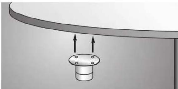
natural_image
Diagram of a mechanical component with two upward arrows indicating direction (no text or symbols)Figure 1
Mounting the
SolidDrive
MSK-1sm-T to
a table.
Once you have determined where to mount the SolidDrive MSK-1sm-T, spray a thin layer of 3M ^® Super 77 adhesive on the bottom of the SolidDrive, then use the appropriate length wood screws to attach it securely to the surface. The adhesive improves the sonic transmission between the drive and the surface. The best mounting location is typically out of sight on the underside or back of desks, counter tops, conference tables, or other office/home furniture. The four pre-drilled mounting holes on the SolidDrive MSK-1sm-T oversized mounting base will hold screws as large as #9.
Some installations may require that pilot holes be drilled into the surface material due to its hardness, especially if larger, coarse thread screws are used.
INSTALLATION OF SOLIDDRIVE MSK-1g-T TO GLASS SURFACES
For installation on glass surfaces, the SolidDrive MSK-1g-T comes with a VHB double-sided adhesive disc.
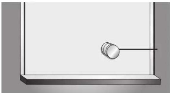
natural_image
Simple line drawing of a pendulum hanging from a horizontal rod inside a rectangular frame (no text or symbols)Figure 1
Mounting the
SolidDrive
MSK-1g-T to
glass.
The SolidDrive MSK-1g-T should be mounted in an inconspicuous location of the window. Simply apply the VHB pad that comes with the drive to the base of the drive (the side opposite the label). Remove one side of the protective layers from the VHB disc and apply to the base of the MSK-1g-T. Then remove the other protective layer and apply to glass surface with moderate pressure.
When mounting the SolidDrive on the window, keep it about 4 to 6 inches from the window frame. The SolidDrive MSK-1g-T will have maximum output with at least 20 square feet of window surface space.