
MKC68GR - Neklasifikuota Atosa - Nemokama naudojimo instrukcija
Raskite įrenginio instrukciją nemokamai MKC68GR Atosa PDF formatu.

Naudotojų klausimai apie MKC68GR Atosa
0 klausimas apie šį prietaisą. Atsakykite į tas, kurias žinote, arba užduokite savo.
Užduokite naują klausimą apie šį prietaisą
Atsisiųskite instrukciją savo Neklasifikuota PDF formatu nemokamai! Raskite savo instrukciją MKC68GR - Atosa ir vėl perimkite savo elektroninį įrenginį. Šiame puslapyje skelbiami visi dokumentai, reikalingi jūsų įrenginio naudojimui. MKC68GR prekės ženklo Atosa.
NAUDOJIMO INSTRUKCIJA MKC68GR Atosa
In order to provide the best service, ATOSA
requests that please register your warranty online
at www.atosausa.com
For any service issues, please kindly contact us at
Email:warranty@atosausa.com
or
Toll Free:+1-800-683-8660
Please clean the filter frequently!
Please do not overload the unit!
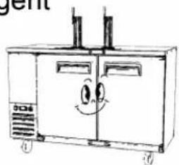
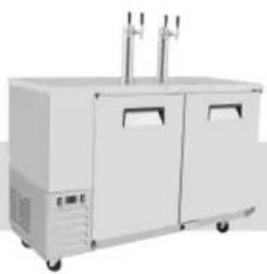
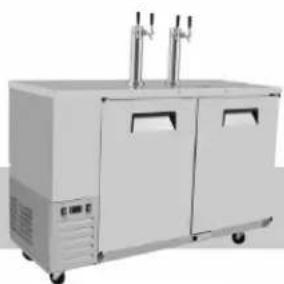
INSTRUCTION MANUAL Direct Draw Keg Refrigerators
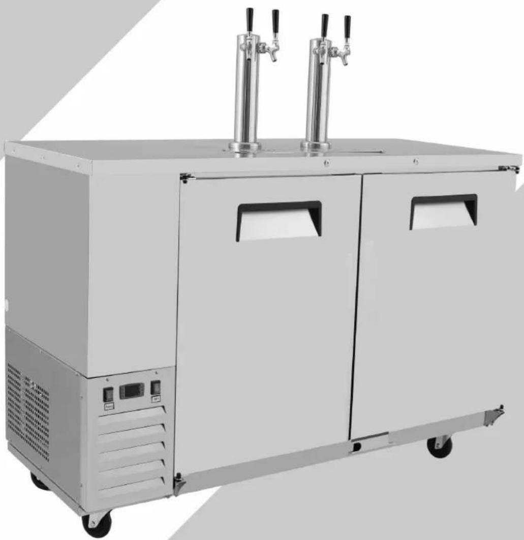
natural_image
Exterior view of a stainless steel industrial control unit with two vertical pressure vessels (no visible text or symbols)Keg beer coolers Installation, use and maintenance instructions
Content:
1 Terms and conditions....2
2.Preface....6
3. Use of the equipment....9
4. Technical features....9
5.Operation....9
6.Control unit....10
7. Handling....10
8. Installation procedure....11
9. Connecting to the main power supply......11
10. Maintenance instructions....12
Cleaning....12
Cleaning the refrigerator surface....12
Cleaning the inside of the refrigerator....13
Cleaning the condenser....13
11.Troubleshooting....13
12. Technical service....13
Operating Instruction....14
Technical Parameters....19
Official Approval And Rules....19
Drilling ports for CO2 Lines....20
1 TERMS AND CONDITIONS:
Refrigeration
2 YEAR WARRANTY
All claims for parts or labor must be made directly through Atosa. All claims must include: model number of the unit, the serial number, proof of purchase, date of installation, and all pertinent information supporting the alleged defect. In case of compressor replacement under warranty, either compressor or compressor tag must be returned to Atosa along with above listed information. Failure to comply with warranty policies will result in voiding claims.
Two Year Parts & Labor Warranty
Atosa warrants all new refrigerated components, such as the cabinet and all parts, to be free from defects in materials or workmanship. Atosa ‘s obligation under this warranty is limited to a period of two (2) years from the date of original installation or 27 months after shipment date from Atosa, whichever occurs first. All parts covered under this warranty that are defective within two (2) years of original installation or twenty seven (27) months after shipment date from manufacturer, whichever occurs first, are limited to repair or replacement (including labor charges, of defective parts or assemblies). The labor warranty shall include standard straight time labor charges only and reasonable travel time, as determined by Atosa.
Additional Three Year Compressor Warranty
In addition to the two (2) year warranty stated above, Atosa warrants its sealed compressor to be free from defects in both material and workman ship under normal and proper use and maintenance service for a period of three (3) additional years from the date of original installation, but not to exceed five (5) years. Compressors that have been determined to be defective from Atosa within this extended period will be either repaired or replaced with a compressor or compressor parts of similar design and capacity according to Atosa ‘s discretion. The three (3) year extended compressor warranty applies only to sealed parts of the compressor and does not apply to any other parts or components. This includes, the cabinet, paint finish, temperature control, refrigerant, metering device, motor starting equipment, fan assembly, and other electrical components, etc.
R290 Compressor Warranty
The five-year compressor warranty detailed above will be void if the following procedure is not carefully adhered to:
-
This system contains R290 refrigerant and lubricant. The lubricant has rapid moisture absorbing qualities.
-
Drier replacement is very important and must be changed when a system is opened for servicing.
-
Micron level vacuums must be achieved to insure low moisture levels in the system.
-
Compressor must be obtained through Atosa, unless otherwise specified in writing, through Atosa's warranty department.
What is Not Covered by This Warranty
Atosa ‘s sole obligation under this warranty is limited to either repair or replacement of parts, subject to the additional limitationsbelow. This warranty neither assumes nor authorizes any person to assume obligations other than those expressly covered by thiswarranty.
NO CONSEQUENTIAL DAMAGES: ATOSA IS NOT RESPONSIBLE FOR ECONOMIC LOSS; PROFIT LOSS; OR SPECIAL,INDIRECT, OR CONSEQUENTIAL DAMAGES, INCLUDING WITHOUT LIMITATION, LOSSES, OR DAMAGES ARISING FROMFOOD OR PRODUCT SPOILAGE, REGARDLESS OF WHETHER OR NOT THEY RESULT FROM REFRIGERATION FAILURE.
WARRANTY IS NOT TRANSFERABLE: This warranty is not assignable and applies only in favor of the original purchaser/user to whom delivered. ANY SUCH ASSIGNMENT OR TRANSFER SHALL VOID THE WARRANTIES HEREIN AND SHALL VOID ALL WARRANTIES, EXPRESS OR IMPLIED, INCLUDING ANY WARRANTY OF MERCHANTABILITY OR LABOR COVERAGE FORCOMPONENT FAILURE OR OTHER THE WARRANTY PACKET PROVIDED WITH THE UNIT.
ALTERATION, NEGLECT, ABUSE, MISUSE, ACCIDENT, DAMAGE DURING TRANSIT OR INSTALLATION, FIRE, FOOD, OR ACTSOF
GOD: Atosa is not responsible for the repair or replacement of any parts that are determined to have been subjected after the date of manufacture to alteration, neglect, abuse, misuse, accident, damage during transit or installation, fire, flood, or act of God.
IMPROPER ELECTRICAL CONNECTIONS: Atosa IS NOT RESPONSIBLE FOR THE REPAIR OR REPLACEMENT OF FAILED OR DAMAGED COMPONENTS RESULTING FROM ELECTRICAL POWER FAILURE, THE USE OF EXTENSION CORDS, LOW VOLTAGE, OR VOLTAGE DROPS TO THE UNIT. THE TWO (2) YEAR PARTS & LABOR WARRANTY AND THE ADDITIONAL THREE (3) YEAR COM-PRESSOR WARRANTY ARE AS DESCRIBED ABOVE. THESE WARRANTIES ARE EXCLUSIVE AND IN LIEU OF ALL OTHER WARRANTIES, INCLUDING IMPLIED WARRANTY AND MERCHANTABILITY OR FITNESS FOR A PARTICULAR PURPOSE. THERE ARE NO WARRANTIES WHICH EXTEND BEYOND THE DESCRIPTION ON THE FACE HEREOF.
Outside U.S. and Canada: This warranty does not apply to areas outside the continent of the United States. Atosa is not responsible for any warranty claims made on products sold or used in such areas.*In some cases, a 25% restocking fee may be charged to a buyer for returned items.*Atosa may at any time modify our equipment in order to provide and insure a superior product. Change is sometimes necessary to keep up with today's high standards in our industry. Atosa reserves the final interpretation of all public materials.
2 Preface
Please read instructions before using this appliance.
IMPORTANT SAFETY INSTRUCTION
▲ To reduce the risk of fire, electric shock, or injury to persons when using your product, basic safety precautions should be followed, including the following.
▲ This appliance must be properly installed and located in accordance with the Installation Instruction before it is used.
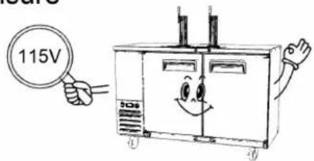
▲ Before the appliance is plugged in, ensure that the rated voltage corresponds to the voltage of the electrical system in your home. The power plug should have its own independent socket. Using adapters may cause overheating or burning.
▲ This appliance can be used by children aged from 8 years and above and persons with reduced physical, sensory or mental capabilities or lack of experience and knowledge if they have been given supervision or instruction concerning use of the appliance in a safe way and understand the hazards involved.
▲ Children shall not play with the appliance.
▲ Cleaning and user maintenance shall not be made by children without supervision.
▲ If the supply cord is damaged, it must be replaced by the manufacturer or its service agent or a similarly qualified person in order to avoid a hazard.
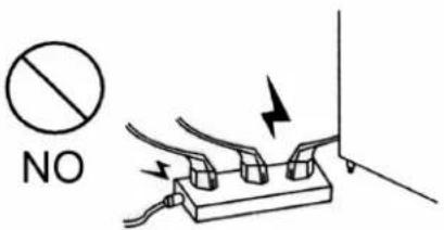
▲ Connect to properly grounded outlets only. Avoid the use of extension cords. Do not run cord under carpeting, runners or the like. Arrange cord away from traffic area and where it will not create a tripping hazard.
▲ Always unplug appliance when not in use and before cleaning, adjusting or maintaining this machine. To disconnect appliance, turn switch off and remove plug from power source.
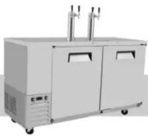
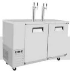
natural_image
Exterior view of a modern stainless steel industrial machine with two vertical control valves (no visible text or symbols)▲ Do not disconnect by pulling on the cord. Always disconnect by grasping and pulling on the plug top.
▲ Do not pull out the cord or touch the power plug with wet hands. Clean water or dust from the power plug and insert it with the ends of the pins securely connected.
▲ Do not use outdoors.
▲ Do not splash water on the appliance. It may cause a malfunction or electric shock.
▲ Do not disassemble, repair or alter the appliance. It may cause fire or abnormal operations, which may lead to injury.
▲ After your fridge-freezer is in operation, do not touch the cold surfaces in the freezer compartment, particularly when hands are damp or wet. Skin may adhere to these extremely cold surfaces.
▲ Never place glass products in the freezer because they may be broken when their inner contents are frozen.
▲ The refrigerant and insulation blowing gas used in the appliance require special disposal procedures. When disposal, please consult with service agent or a similarly qualified person.
▲ Do not store explosive substances such as aerosol cans with a flammable propellant in this appliance.
▲ WARNING: Keep clear of obstruction all ventilation openings in the appliance enclosure or in the structure for building-in.
▲ WARNING: Do not use mechanical devices or other means to accelerate the defrosting process, other than those recommended by the manufacturer.
▲ WARNING: Do not damage the refrigerant circuit.
▲ WARNING: Do not use electrical appliances inside the food storage compartments of the appliance, unless they are of the type recommended by the manufacturer.
Warning: Risk of fire / flammable materials
CAUTION: RISK OF FIRE AND EXPLOSION WITH FLAMMABLE
REFRIGERANT R290.
▲ If you need the electronic version instruction manual, please ask the manufacturer or its service agent.
▲ Max. Load of shelf is 88 LBS.
This instruction manual provides all the necessary information regarding:
▲ use of the refrigerator
▲ technical specifications
▲ installation and handling
▲ operator procedures and instructions
▲ maintenance operation
The manual is to be considered an integral part of the refrigerator and should be stored in a safe place for father consult to permit a good working life of the refrigerator.
The appliance is intended for commercial use only.
■ Component parts shall be replaced with like components and that servicing shall be done by factory authorized service personnel.
The A-weighted emission sound pressure level is below 70 dB(A)
The manufacturer cannot be held liable in the following cases:
■ improper installation (not in accordance with the guidelines indicated herein)
■ misuse of the refrigerator
■ power supply defects
■ improper or inadequate maintenance
■ unauthorised modification or tampering
■ use of non-original spare parts
■ partial or total failure to comply with the instructions
All electrical equipment can be hazardous to health. Current standards and legal requirements must be complied with during the installation and use of any equipment.
3. Use of the equipment
The refrigerator are for preserving fresh perishable foodstuffs, with an in-built refrigerated unit.
Do not utilise the equipment to store medical supplies.
Climate class of the equipments is 4 or 5.
The optimum operational ambient temperatures are between +50°F to +110°F
The possible application are: keg beer.
4. Technical features
The refrigerator is a ventilated system, the evaporator is in a separate insulated box on the top. All the materials used in the manufacture of this unit are guaranteed to be suitable for use with foodstuffs. The gases used in produces is R290 ..The refrigerating circuit are in compliance with the current normative.
5. Operation
The gas in the refrigerating circuit is in the first time compressed, liquefied and then evaporated in the ventilated evaporator, situated on the top of the container.
This cycle involves the absorption of heath from the air in the refrigerator compartment and the reason is cooled. The heat produced is then dissipated to the outside environment by a condenser unit located on the top of the refrigerator.
6. Control unit
The refrigerator is command from a “digital control unit” and a “main switch pilot light” in the top panel of the refrigerator.
The "main switch pilot light" is for turning on the power supply.
The red pilot light comes on to indicate that the unit is connected to the main electricity and to start work.
The red pilot light comes off to indicate that the unit is disconnected and don’t work. The “digital control unit” is for the regulation of all parameters to provide the correct working of the refrigerator. Please consult all parameters in the attachment manual of the “digital control unit”.
This manual is part of the instruction manual and is very important in case of service.
Applied refrigerant belong to non-flammable refrigerant.
7. Handling
The refrigerator arrive in PET film and packed in cardboard box on a wood pallet.

The refrigerator must be transported and handled with care to avoid posing a hazard to persons or property.
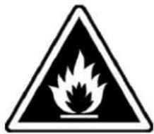
Never place a refrigerator with an in-built refrigerated unit on its side or turn it upside
natural_image
Simple line drawing of two people interacting around a large rectangular table (no text or symbols)down as this may damage or impair operation of the refrigerated unit. We can not held liable for any damage or defects arising directly or indirectly from improper handling of the equipment or non-compliance with the safeguards illustrated above.
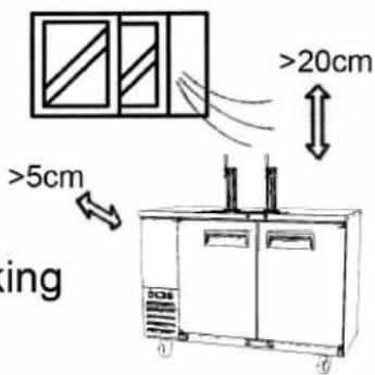
8. Installation procedure
▲ Place the refrigerator in the coolest and best ventilated part of the room. Don’t install the refrigerator in the near of heat and direct sunlight sources.
▲Remove the straps securing the cardboard packing
Remove the cardboard. Covering
Remove the PET protection film
▲ Clean the refrigerator with mild detergent and then dry it with a soft cloth.
natural_image
Cartoon illustration of a smiling industrial machine with hands holding cash, no text or symbols present9 Connecting to the main power supply

This operation must be carried out by professionally and qualified persons.
The refrigerator are supplied complete with a power supply cable for the connection to the main power supply. A thermomagnetic circuit breaker (not supplied) must be installed between the mains power point and the power supply cable of the refrigerator.
Before proceeding make sure that:
▲ the mains voltage corresponds to the voltage on the refrigerator 110V-120V/60Hz/1Ph; to ensure
proper operation it is essential for the power supply voltage to come within a range of +/- 6% of the unit's rated voltage
▲ the electric system to which the refrigerator is sized to cater for the rated electric output of the buffet unit being installed
▲ the electronic system to which the refrigerator is connected is made in compliance with current standard requirements
▲ the electric connections and the installation of the thermomagnetic circuit breaker have been done by qualified person.
Connecting steps:
▲ Install a thermomagnetic circuit breaker suited to the rated output of the unit being installed
▲ Connect the refrigerator unit to the thermomagnetic circuit breaker outlet
▲ Check that the refrigerator is in order as demonstrated by the pilot light incorporated in the main switch coming on
10. Maintenance instructions
The smooth operation and life of the equipment are mainly determined by correct and regular maintenance
Cleaning:
Regular cleaning of the refrigerator unit is strongly recommended each month. Please follow the instructions below.

Disconnect the refrigerator power supply cable from the mains prior to carrying out any type of cleaning operation.
Cleaning the refrigerator surface:
Clean the refrigerator with mild detergent and then dry it with a soft cloth.
Do not use abrasive detergents!
natural_image
Simple line drawing of a cartoon-style industrial machine with a smiling face (no text or symbols)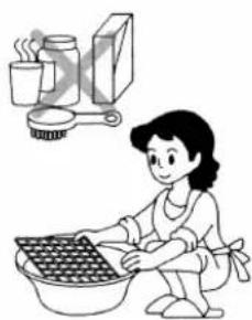
natural_image
Illustration of a woman washing dishes with a kitchen appliance in the background (no text or symbols)Cleaning the inside of the refrigerator:
Clean the inside area min. each month with a detergent suitable for use with foodstuffs.
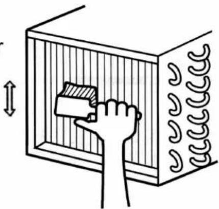
Cleaning the condenser:
For an efficient operation of the refrigerator it is advisable to clean the condenser regularly approx. every 4 months with a dry brush or vacuum cleaner.
natural_image
Diagram of a hand placing a component into a rectangular chamber with coiled structures (no text or symbols)11. Troubleshooting
Refrigerator stops working (light off):
☆ Power supply failure
▲ Remedies:
☆ Check that the plug is inserted properly in the socket
☆ Check that the switch on/off
☆ Check that the mains voltage powers the plug
Refrigerator temperature go up:
☆ Unit to near to a heat source
☆ Condenser dirty or close
▲ Remedies:
☆ Move the counter or the heat source further away
☆ Clean the condenser
12. Technical service
For technical service please contact the dealer technical department and give him the serial number, and the date of buy.
Operating Instruction
- New upright air-cooling refrigerator should be opened and ventilate it before it is in use. After that, users should use warm water clean its inside.
- After connecting the power supply, press the "POWER" switch on the controller keyboard (Green Indicator Light ON), the fridge will come to work. The microcomputer controller, installed in the controller keyboard, could automatically adjust the temperature ranges. This intelligent digital controller works as: if the temperature increases and reaches set point plus differential the compressor is started and then turned off when the temperature reaches the set point value again.
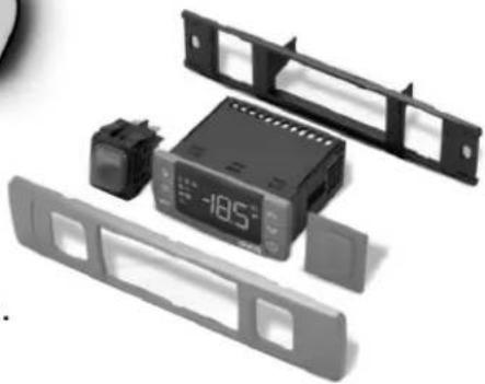
- Microcomputer Controller Operation Instruction:
- Microcomputer panel sketch map, meanings of running indicator light and LED showing.
- SET To display target set point, in programming mode it selects a parameter or confirm an operation.

To start a manual defrost.
In programming mode it browses the parameter codes or increases the displayed value.

In programming mode it browses the parameter codes or
decreases the displayed value.
+ To lock or unlock the keyboard SET+ To enter in programming mode SET+ To return to room temperature display.
natural_image
Disassembled electronic device with a digital display and control panel (no visible text or symbols)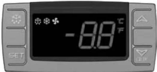
(Mod. XR06CX)
| LED | MODE | SIGNIFICATO |
| On | Compressor enabled | |
| Flashing | Anti short cycle delay enabled (AC parameter) | |
| On | Defrost in progress | |
| Flashing | Dripping in progress | |
| On | Fans output enabled | |
| Flashing | Fans delay after defrost | |
| On | Measurement unit | |
| Flashing | Programming mode | |
| On | Measurement unit | |
| Flashing | Programming mode |
natural_image
Exterior view of a two-door industrial control cabinet with dual doors and side fans (no visible text or symbols)- How to see the point .
Push and immediately release the SET key, the set point will be showed; Push and immediately release the SET key or wait about 5s to return to normal visualisation.
- How to change the setpoint.
Push the SET key for more than 2 seconds to change the Set point value; The value of the set point will be displayed and the “°C” or “°F” LED starts blinking;
To change the Set value push the △ or ▽ AUX arrows.
To memorise the new set point value push the SET key again or wait 10s.
- How to start a manual defrost.
Push the DEF ✦ key for more than 2 seconds and a manual defrost will start.
- How to change a parameter value
To change the parameter's value operate as follows:
Enter the Programming mode by pressing the SET+▼ keys for 3s ("°C" or "°F" LED starts blinking).
Select the required parameter. Press the "SET" key to display its value Use △ or ▽ AUX to change its value.
Press "SET" to store the new value and move to the following parameter.
To exit: Press SET+△ or wait 15s without pressing a key.
NOTE: the set value is stored even when the procedure is exited by waiting the time-out to expire.
- To lock the keyboard.
Keep pressed for more than 3s the ▽+△ keys.
The “OF” message will be displayed and the keyboard will be locked. If a key is pressed more than 3s the “OF” message will be displayed.
- To unlock the keyboard.
Keep pressed together for more than 3s the ▽+▲ keys till the “on” message will be displayed.
- Alarm signalling.
| Mess. | Cause | Outputs |
| "P1" | Room probe failure | Compressor output according to “Cy” e “Cn” |
| "P2" | Evaporator probe failure | Defrost end is timed |
| "HA" | Maximum temperature alarm | Outputs unchanged |
| "LA" | Minimum temperature alarm | Outputs unchanged |
| “EA” | External alarm | Outputs unchanged |
| “CA” | Serious external alarm | All outputs OFF |
| “dA” | Door Open | Compressor and fans restarts |
Our products have been modified precisely before leaving factory, so to avoid damaging compressor unit or other malfunctions, users mustn’t modify the microcomputer parameters privately.
natural_image
Exterior view of a white industrial control unit with dual vertical gauges and wheels (no visible text or symbols)CAREL: PJEZ*
Display and functions:
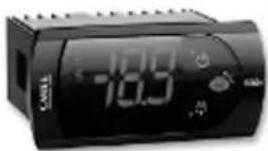
During normal operation, the controller displays the value of the probe set using parameter/4(=1 ambient probe, default, =2 second probe, =3 third probe). In addition, the display has LEDs that indicate the activation of the control functions (see Table 1), while the 3 buttons can be used to activate/deactivate some of the functions (see table 2).
LEDs and associated functions Tab.1
| icon | function | normal operation | start up | ||
| ON | OFF | blink | |||
 | Compressor | on | off | request | ON |
 | fan | on | off | request | ON |
 | defrost | on | off | request | ON |
 | aux | output on | output off | - | ON |
 | alarm | all | no alarm | - | ON |
 | clock | RTC fitted and enabled,at least 1 time band set | RTC not fitted or disabled,not even 1 time band set | - | ON if RTC fitted |
Table of functions activated by the buttons Tab.2
| button | normal operation | start up | ||||
| pressing the button alone | pressed together | |||||
 | upON/OFF | more than 3s toggleON/OFF | pressedtogether start/stop continuouscycle | - | ||
 | downdefrost | more than 3s:start/stop defrost | Pressedtogetherstartparameterresetprocedure | for 1s displayfirmware vers.code | ||
 | setmute | -1s: display/set the set point-more than 3s: access parametersetting menu(enter password 22)-mute audible alarm (buzzer) | - | for 1s RESETcurrent EZYset | ||
Setting the set point(desired temperature)
- press SET for 1s the set value will start flashing after a few moments;
- increase or decrease the value using UP or DOWN;
- press SET to confirm the new value.
Switching the device ON/OFF
Press UP for more than 3s. the control and defrost algorithms are now disabled and the instrument displays the message "OFF" alternating with the temperature read by the set probe.
Manual defrost
Press for DOWN more than 3s (the defrost starts only the temperature conditions are valid).
Continuous cycle
Press UP and DOWN together for more than 3s.
Table of alarms
| Alam code | buzzer and alarm relay | LED | Description | Parametri coninvolti |
| E0 | active | ON | probe 1 error=control | - |
| E1 | inactive | ON | probe 2 error=defrost | [d0=0/1] |
| E2 | inactive | ON | probe 3 error=condenser | [A4=10] |
| IA | active | ON | external alarm | [A4=10][+A7] |
| dOr | active | ON | open door alarm | [A4=7/8][+A7] |
| LO | active | ON | low temperature alarm | [AL][Ad] |
| HI | active | ON | high temperature alarm | [Ah][Ad] |
| EE | inactive | ON | unit parameter error | - |
| EF | inactive | ON | operating parameter error | - |
| Ed | inactive | ON | defrost ended by timeout | [dP][dt][d4][A8] |
| dF | inactive | ON | defrost running | [d6=0] |
| cht | inactive | ON | condenser dirty pre-alarm | [A4=10] |
| CHT | active | ON | condenser dirty alarm | [A4=10] |
| EtC | inactive | ON | clock alarm |
Technical Parameters
| Model code | Power source (V) | Rating frequency(Hz) | Input power (w) | Rated current(A) | Temperature range (°F) | Refrigerant | Amount(oz) | Dimension (in) | Volume (cu.ft) |
| MKC23GR | 115 | 60 | 260 | 2.3 | +32~+50 | R290 | 2.8 | 23×29.5×39.3 | 7.09 |
| MKC58GR | 115 | 60 | 260 | 2.3 | +32~+50 | R290 | 4.2 | 57.8×28.1×42.2 | 17.3 |
| MKC68GR | 115 | 60 | 260 | 2.3 | +32~+50 | R290 | 4.2 | 68×28.1×42.2 | 21.5 |
| MKC90GR | 115 | 60 | 320 | 2.8 | +32~+50 | R290 | 4.2 | 89.3×28.1×42.2 | 30.1 |
NOTES : If the technical data has any changes, we will not notify you any longer.
OFFICIAL APPROVAL AND RULES
CONFORMS TO UL STD.471
CERTIFIED TO CSA STD.C22.2 NO.120
CONFORMS TO NSF/ANSI STD. 7

Intertek
4003935
CONFORMS TO UL STD.471
CERTIFIED TO CSA STD.C22.2 NO.120

Intertek
4003935
CONFORMS TO NSF/ANSI STD.7
Drilling Ports For CO2 Lines
Applicable Serial Numbers
MKC23GR/MKC58GR/MKC68GR MKC90GR
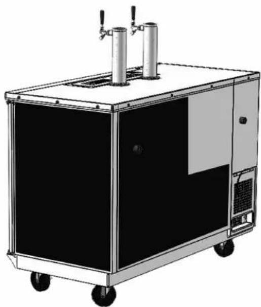
natural_image
Illustration of a black industrial machine with two vertical cylindrical tanks and a control panel, mounted on wheels (no text or symbols visible)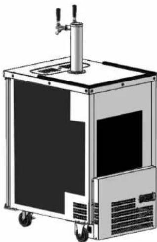
natural_image
Illustration of a mechanical device with a vertical cylindrical top and control panel, no text or symbols present.Left Back View
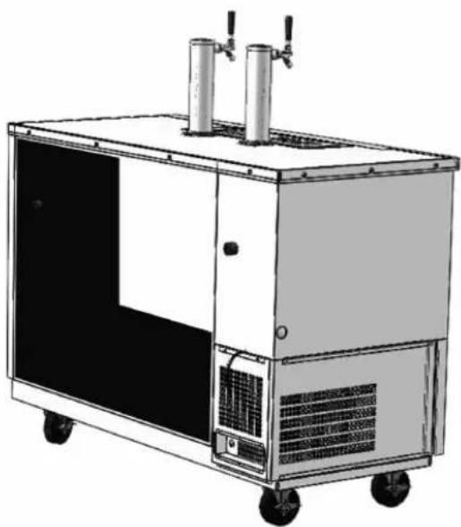
natural_image
Illustration of a laboratory equipment cabinet with two vertical tanks and control panels, no visible text or symbols.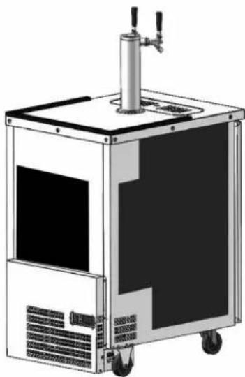
natural_image
Illustration of a mechanical device with a cylindrical top and wheels, no visible text or symbolsRight Back View
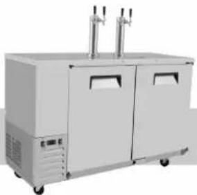
To avoid damaging refrigeration components and wiring, please drill holes for CO2 lines only in the shadow areas.
natural_image
Exterior view of a two-door industrial refrigeration unit with control panels and side-mounted fans (no visible text or symbols)*Air distributor is only on multiple keg units, each keg is conneted to a valve on the air distributor.
Single keg is connected directly to the regulator.
NOTE
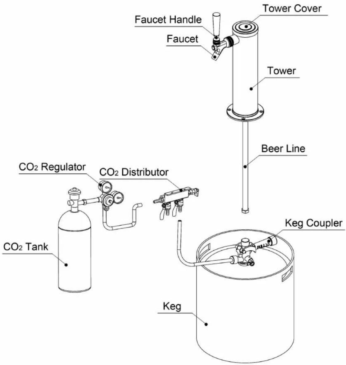
The keg, keg coupler, CO2 regulator, CO2 tank, kegcoupler to CO2 distributor line, and CO2 distributor to CO_2 regulator line, are not included with your keg refrigerator.
These items can be obtained from your beverage distributor. The beer tower with faucet, faucet handle, tower beer line, and CO_2 distributor are included.
natural_image
Exterior view of a modern industrial water treatment machine (no visible text or symbols)- Position tower gasket so that the drain line and screw holes align properly with the top surface of the unit. Feed the tower's beer line through the unit's beer line hole.
natural_image
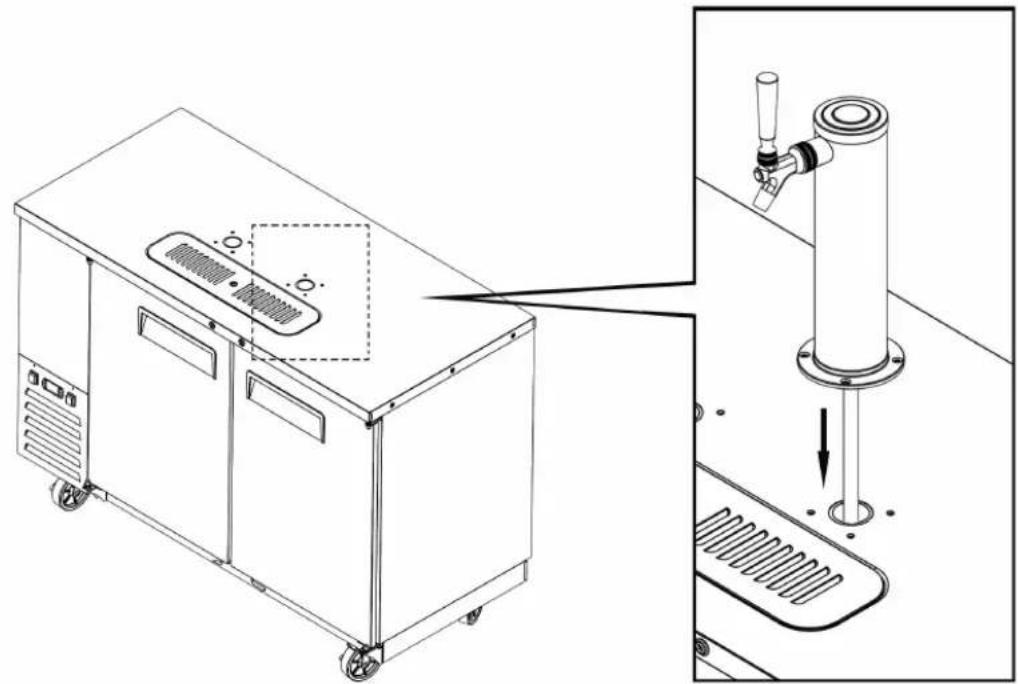
Technical line drawing of a laboratory apparatus with a side view showing a test tube inserted into a container (no text or symbols present)- Secure the tower to the unit using the four screws provided.
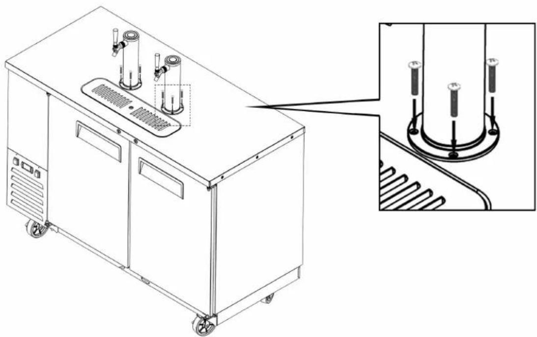
natural_image
Technical line drawing of a mechanical device with labeled components and an inset close-up showing internal wiring (no text or symbols present)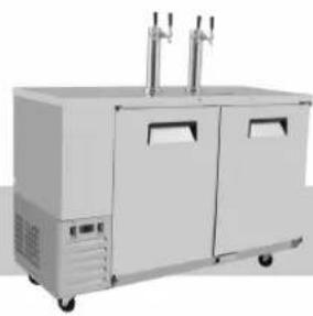
natural_image
Exterior view of a modern industrial water heater or refrigerated unit with two vertical outlets and control panels (no visible text or symbols)- Insert the end of the cold air hose into the air baffle, insert the other end of the cold air hose into the tower.
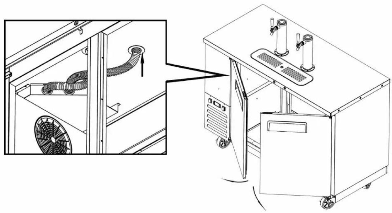
natural_image
Technical line drawing of an industrial machine with fan and cooling unit, showing internal tubing and a close-up view (no text or symbols)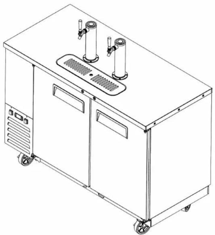
natural_image
Line drawing of a rectangular industrial machine with three cylindrical tanks and a side panel, no text or symbols present.*NOTE: The CO2 distributor can be used to share the single CO2 tank with multiple kegs.
1. CO_2 tank placement (inside or outside of the refrigerated cabinet)
a. Outside of cabinet-Drill a hole on the back wall of the unit, only in the areas indicated in figure; Drilling in any other place may cause damage to the unit's wiring.
b. Inside of cabinet-Depending on the unit model and size of the equipped keg, you may be able to fit the CO_2 tank inside of the refrigerated cabinet; This setup requires no drilling.
2. Connect CO_2 line to CO_2 regulator
a. Ensure that the CO2 regulator's shut off valve is closed. The switch's lever should be perpendicular to the CO2 line when it is in the closed position.
b. Connect one end of the CO2 line to the CO2 regulator's hose barb connection, pushing the hose onto the barb connector as high as you can without damaging the hose. Secure the hose to the connector using a clamp. Place the clamp as high up as possible without it interfering with the operation of the valve.
c. If the CO_2 tank has been placed out of the refrigerated cabinet, feed the hose through the hole that was previously drilled in the back of the unit.
3. Connect CO_2 regulator to CO_2 tank
a. Ensure that the CO_2 tank is full and closed.
b. Attach the CO2 regulator to the CO2 tank using the large nut that is part of the regulator.
4. Connect keg coupler
a. IMPORTANT: Ensure that the keg pull handle is closed (upper position). b. Install the keg coupler onto the keg's locking neck and turn clockwise to lock into place.
5. Connect CO_2 line to keg coupler
a. Connect the open end of the CO_2 line to the keg coupler's hose barb connection, pushing the hose onto the barb connector as high as you can without damaging the hose. Secure the hose to the connector using a clamp. Place the clamp as high up as possible without it interfering with the operation of the valve.
6. Connect beer line to keg coupler
a. Install the rubber washer onto the beer line hex nut fitting.
b. Remove the plastic protective cover from the keg coupler, if equipped.
c. Connect the beer line from the tower to the keg coupler .It connects to the screw type connection on top of the coupler.
7.Tap keg
a.Pull the tap handle out and away from the keg coupler and push down until it locks into position.A click noise should be heard once the handle is in its final lock position.
8.Calibrating CO_2 regulator
a. With the shut-off valve on the CO2 regulator closed, open the valve on the CO2 tank completely.
b. Loosen the adjustment nut with a pair of pliers, allowing the adjustment screw to be turned counter-clockwise until the screw can no longer turn.
c. Slowly turn the CO_2 regulator adjustment screw until the desired pressure is shown on the output pressure gauge (12 PSI is recommended setting for most situations). Other conditions, such as altitude or special beer type, may require some adjustment. On regulators designed for draft beer, turning clockwise will increase the output pressure, and turning counter-clockwise will decrease the output pressure.
d.Open the shut-off valve on the CO_2 regulator, ensuring the switch below the main body should be parallel to the tubing. Gas should now flow from the regulator to the keg coupler, and you will hear the keg pressurizing. The output needle will drop momentarily while the pressure is equalizing, then it will return to the point at which you set it.
natural_image
Exterior view of a modern stainless steel industrial machine with two side doors and control panels (no visible text or symbols)e. The keg coupler is designed with a pressure relief valve (PRV). Pull the ring on the PRV briefly to allow gas to vent. This will permit gas to flow though the regulator and help obtain a more accurate reading on the output pressure gauge.
f. Re-check the output pressure on the regulator and, if necessary, re-adjust using step 8.3 until the desired pressure is shown. It is always wise to follow up any adjustment to the regulator with a brief pull of the PRV ring to ensure an accurate output reading.
9. Position the keg in the refrigerated compartment. Ensure that no hoses are kinked or crushed.
W0811201
version number 20200309


- INSTRUCTION MANUAL Direct Draw Keg Refrigerators
- Keg beer coolers Installation, use and maintenance instructions
- Content:
- TERMS AND CONDITIONS:
- Refrigeration
- YEAR WARRANTY
- Two Year Parts & Labor Warranty
- Additional Three Year Compressor Warranty
- R290 Compressor Warranty
- Preface
- IMPORTANT SAFETY INSTRUCTION
- Warning: Risk of fire / flammable materials
- CAUTION: RISK OF FIRE AND EXPLOSION WITH FLAMMABLE
- REFRIGERANT R290.
- The A-weighted emission sound pressure level is below 70 dB(A)
- The manufacturer cannot be held liable in the following cases:
- Use of the equipment
- Technical features
- Operation
- Control unit
- Handling
- Installation procedure
- Connecting to the main power supply
- Before proceeding make sure that:
- Connecting steps:
- Maintenance instructions
- Cleaning:
- Cleaning the refrigerator surface:
- Cleaning the inside of the refrigerator:
- Cleaning the condenser:
- Troubleshooting
- Technical service
- Operating Instruction
- Display and functions:
- Setting the set point(desired temperature)
- Switching the device ON/OFF
- Manual defrost
- Continuous cycle
- OFFICIAL APPROVAL AND RULES
- Drilling Ports For CO2 Lines
- Applicable Serial Numbers
- MKC23GR/MKC58GR/MKC68GR MKC90GR
- NOTE
- CO_2 tank placement (inside or outside of the refrigerated cabinet)
- Connect CO_2 line to CO_2 regulator
- Connect CO_2 regulator to CO_2 tank
- Connect keg coupler
- Connect CO_2 line to keg coupler
- Connect beer line to keg coupler
- 7.Tap keg
- 8.Calibrating CO_2 regulator
- Position the keg in the refrigerated compartment. Ensure that no hoses are kinked or crushed.
Prekės ženklas : Atosa
Modelis : MKC68GR
Kategorija : Neklasifikuota