
BAVOT 180 NG - Oro kondicionierius BEKO - Nemokama naudojimo instrukcija
Raskite įrenginio instrukciją nemokamai BAVOT 180 NG BEKO PDF formatu.


Naudotojų klausimai apie BAVOT 180 NG BEKO
0 klausimas apie šį prietaisą. Atsakykite į tas, kurias žinote, arba užduokite savo.
Užduokite naują klausimą apie šį prietaisą
Atsisiųskite instrukciją savo Oro kondicionierius PDF formatu nemokamai! Raskite savo instrukciją BAVOT 180 NG - BEKO ir vėl perimkite savo elektroninį įrenginį. Šiame puslapyje skelbiami visi dokumentai, reikalingi jūsų įrenginio naudojimui. BAVOT 180 NG prekės ženklo BEKO.
NAUDOJIMO INSTRUKCIJA BAVOT 180 NG BEKO

Split type air conditioner
User Manual

BAVOT 090 NG/BAVOT 091 NG
BAVOT 120 NG/BAVOT 121 NG
BAVOT 180 NG/BAVOT 181 NG
BAVOT 240 NG/BAVOT 241 NG
EN
CONTENTS
ENGLISH
3-44
Please read this user manual first!
Dear Customer,
Thank you for preferring a Beko product. We hope that you get the best results from your product which has been manufactured with high quality and state-of-the-art technology. Therefore, please read this entire user manual and all other accompanying documents carefully before using the product and keep it as a reference for future use. If you handover the product to someone else, give the user manual as well. Follow all warnings and information in the user manual.
Meanings of the symbols
Following symbols are used in the various section of this manual:

Important information or useful hints about usage.

Warning for hazardous situations with regard to life and property.

Warning to actions that must never perform.

Warning for electric shock.

This symbol shows that information is available such as the operating manual or installation manual.

Do not cover it.

This symbol shows that the operation manual should be read carefully.

This symbol shows that a service personnel should be handling this equipment with reference to the installation manual.

(For R32/R290 gas type)
This symbol shows that this appliance used a flammable refrigerant. If the refrigerant is leaked and exposed to an external ignition source, there is a risk of fire.

This product has been manufactured at modern facilities respectful to the environment without harming nature.
CONTENTS
1 SAFETY PRECAUTIONS 6
2 NAME OF PARTS 10
3 REMOTE CONTROL 12
3.1 COOLING MODE 15
3.2 FAN MODE (Not FAN button) 15
3.3 DRY MODE 15
3.4 AUTO MODE 15
3.5 HEATING MODE....15
3.6 FAN SPEED function (FAN button) 16
3.7 Child-Lock function....16
3.8 TIMER function - TIMER ON....16
3.9 TURBO function 16
3.10 SWING function 17
3.11 SLEEP function.... 17
3.12 I FEEL function 17
3.13 ECO function (Optional Feature) 18
3.14 GEN function 18
3.15 DISPLAY function (Indoor display) 18
3.16 GoClean....18
3.17 8°C heating function (Optional) 19
3.18 Gentle Wind function (Optional) 19
3.19 Health function (Optional) 19
3.20 Wifi reset (Optional) 19
CONTENTS
4 OPERATION INSTRUCTIONS 20
5 INSTALLATION PRECAUTIONS 22
6 INDOOR UNIT INSTALLATION 23
7 OUTDOOR UNIT INSTALLATION 28
8 TEST OPERATION 32
9 MAINTENANCE 34
10 TROUBLESHOOTING 36
11 European disposal guideline 38
12 Installation instructions 39
12.1 F-Gas instruction 39
13 Specifications 40
1 SAFETY PRECAUTIONS
SAFETY RULES AND RECOMMENDATIONS FOR THE INSTALLER
- Read this guide before installing and using the appliance.
- During the installation of the indoor and outdoor units, access to the working area should be forbidden to children. Unforeseeable accidents could happen.
- Make sure that the base of the outdoor unit is firmly fixed.
- Check that air cannot enter the refrigerant system and check for refrigerant leaks when moving the air conditioner.
- Carry out a test cycle after installing the air conditioner and record the operating data.
- Protect the indoor unit with a fuse of suitable capacity for the maximum input current or with another overload protection device.
- Ensure that the mains voltage corresponds to that stamped on the rating plate. Keep the switch or power plug clean. Insert the power plug correctly and firmly into the socket, thereby avoiding the risk of electric shock or fire due to insufficient contact.
- Check that the socket is suitable for the plug, otherwise have the socket
changed.
-
The appliance must be fitted with means for disconnection from the supply mains having a contact separation in all poles that provide full disconnection under over voltage category III conditions, and these means must be incorporated in the fixed wiring in accordance with the wiring rules.
-
The air conditioner must be installed by professional or qualified persons.
-
Do not install the appliance at a distance of less than 50 cm from inflammable substances (alcohol, etc.) Or from pressurized containers (e.g. spray cans).
-
If the appliance is used in areas without the possibility of ventilation, precautions must be taken to prevent any leaks of refrigerant gas from remaining in the environment and creating a danger of fire.
-
The packaging materials are recyclable and should be disposed of in the separate waste bins. Take the air conditioner at the end of its useful life to a special waste collection center for disposal.
-
Only use the air conditioner as instructed in this booklet. These instructions are not intended to cover every possible condition and situation. As with any electrical household
1 SAFETY PRECAUTIONS
appliance, common sense and caution are therefore always recommended for installation, operation and maintenance.
-
The appliance must be installed in accordance with applicable national regulations.
-
Before accessing the terminals, all the power circuits must be disconnected from the power supply.
-
The appliance shall be installed in accordance with national wiring regulations.
-
This appliance can be used by children aged from 8 years and above and persons with reduced physical, sensory or mental capabilities or lack of experience and knowledge if they have been given supervision or instruction concerning use of the appliance in a safe way and understand the hazards involved. Children shall not play with the appliance. Cleaning and user maintenance shall not be made by children without supervision. Keep the appliance and its cord out of reach of children aged less than 8 years.
-
Do not try to install the conditioner alone, always contact specialized technical personnel.
-
Cleaning and maintenance must be carried out by specialized technical personnel. In any case disconnect the
appliance from the mains electricity supply before carrying out any cleaning or maintenance.
-
Ensure that the mains voltage corresponds to that stamped on the rating plate. Keep the switch or power plug clean. Insert the power plug correctly and firmly into the socket, thereby avoiding the risk of electric shock or fire due to insufficient contact.
-
Do not pull out the plug to switch off the appliance when it is in operation, since this could create a spark and cause a fire, etc.
-
This appliance has been made for air conditioning domestic environments and must not be used for any other purpose, such as for drying clothes, cooling food, etc.
-
Always use the appliance with the air filter mounted. The use of the conditioner without air filter could cause an excessive accumulation of dust or waste on the inner parts of the device with possible subsequent failures.
-
The user is responsible for having the appliance installed by a qualified technician, who must check that it is earth in accordance with current legislation and insert a thermos magnetic circuit breaker.
1 SAFETY PRECAUTIONS
- The batteries in the remote controller must be recycled or disposed of properly. For disposal of scrap batteries, please discard the batteries as sorted municipal waste at the accessible collection point.
- Never remain directly exposed to the flow of cold air for a long time. The direct and prolonged exposition to cold air could be dangerous for your health. Particular care should be taken in the rooms where there are children, old or sick people.
- If the appliance gives off smoke or there is a smell of burning, immediately cut off the power supply and contact the Service Center.
- The prolonged use of the device in such conditions could cause fire or electrocution.
- Have repairs carried out only by an authorised Service Centra of the manufacturer. Incorrect repair could expose the user to the risk of electric shock, etc.
- Unhook the automatic switch if you foresee not to use the device for a long time. The airflow direction must be properly adjusted.
- The flaps must be directed downwards in the heating mode and upwards in the cooling mode.
- Ensure that the appliance is disconnected from the power supply
when it will remain inoperative for a long period and before carrying out any cleaning or maintenance.
- Selecting the most suitable temperature can prevent damage to the appliance.
SAFETY RULES AND PROHIBITIONS
- Do not bend, tug or compress the power cord since this could damage it. Electrical shocks or fire are probably due to a damaged power cord. Specialized technical personnel only must replace a damaged power cord.
- Do not use extensions or gang modules.
- Do not touch the appliance when barefoot or parts of the body are wet or damp.
- Do not obstruct the air inlet or outlet of the indoor or the outdoor unit. The obstruction of these openings causes a reduction in the operative efficiency of the conditioner with possible consequent failures or damages.
- In no way alter the characteristics of the appliance.
- Do not install the appliance in environments where the air could contain gas, oil or sulphur or near sources of heat.
- This appliance is not intended for use by persons (including children) with
1 SAFETY PRECAUTIONS
reduced physical, sensory or mental capabilities, or lack of experience and knowledge, unless they have been given supervision or instruction concerning use of the appliance by a person responsible for their safety.
- Do not climb onto or place any heavy or hot objects on top of the appliance.
- Do not leave windows or doors open for long when the air conditioner is operating.
- Do not direct the airflow onto plants or animals.
- A long direct exposition to the flow of cold air of the conditioner could have negative effects on plants and animals.
- Do not put the conditioner in contact with water. The electrical insulation could be damaged and thus causing electrocution.
- Do not climb onto or place any objects on the outdoor unit.
- Never insert a stick or similar object into the appliance. It could cause injury.
- Children should be supervised to ensure that they do not play with the appliance. If the supply cord is damaged, it must be replaced by the manufacturer, its service agent or similarly qualified persons in order to avoid a hazard.
2 NAME OF PARTS
Indoor Unit

2 NAME OF PARTS

Note: This figure shown may be different from the actual object. Please take the latter as the standard.
Indoor Display


| No. | LED | Function |
| 1 | 88 | Indicator for Timer, temperature and Error codes. |
| 2 | Lights up during Timer operation. | |
| 3 | SLEEP mode |

Warning:
The shape and position of switches and indicators may be different according to the model, but their function is the same.
3 REMOTE CONTROL
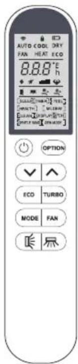
Remote control DISPLAY
Meaning of symbols on the liquid crystal display
| No. | Symbols | Meaning |
| 1 | Signal indicator | |
| 2 | Child Lock function indicator | |
| 3 | Battery indicator | |
| 4 | AUTO | Mode Auto function indicator |
| 5 | COOL | Mode Cooling indicator |
| 6 | DRY | Mode Dry indicator |
| 7 | FAN | Mode Fan indicator |
| 8 | HEAT | Mode Heating indicator |
| 9 | ECO | ECO indicator |
| 10 | 23h [TIMER] | Timer indicator |
| 11 | 88°F | Temperature indicator |
| 12 | Fan speed indicator:Auto/low/mid-low/mid/mid-high/high | |
| 13 | Mute indicator | |
| 14 | Turbo indicator | |
| 15 | Flap swing angle indicator | |
| 16 | Deflector swing angle indicator | |
| 17 | Comfortable cooling airflow indicator | |
| 18 | Comfortable heating airflow indicator | |
| 19 | Optional functions indicator |
![AUTO COOL DRY FAN HEAT ECO 8.8.8 °E [ALABED] [TURBO] [MINI] [WEALTH] [MILKINI] [GUANG] [DISPLAY] [CHI] [WHIP] [WIND] [OVID] OPTION GEN TURBO MODE FAN](/content/2026/05/1110076/images/e1b5c461d3312ed2fa31cc573d28953c0bc635e7b6ecaef8252e71f14d4a10cf.jpg)
3 REMOTE CONTROL

Warning:
You will hear a beep when you press the following buttons or select the following optional functions.

(Optional Function: COMFORTABLE COOLING airflow)

(Optional Function: COMFORTABLE HEATING airflow)

(Optional Function: 8°C Heating)
HEALTH (Optional Function: generate the ionizer)

(button: SWING LEFT/RIGHT)

(Optional Function: Wide-angle air supply)
| No. | Button | Function |
| 1 | To turn on or off the air conditioner. | |
| 2 | OPTION | To activate or deactivate optional function (Check below table). |
| 3 | To decrease temperature, time setting or choose the function. | |
| 4 | To increase temperature, time setting or choose the function. | |
| 5 | ECO | Press this button to activate/deactivate the ECO function. |
| GEN | To activate/deactivate the GEN function which enables the unit run in the set current level, cycle as below "OFF→L3→L2→L1" | |
| 6 | TURBO | Press this button to activate/deactivate the Super function which enables the unit to reach the preset temperature in the shortest time. |
| 7 | MODE | To select the mode of operation (AUTO COOL DRY FAN HEAT). |
| 8 | FAN | To select the fan speed of auto / mute / low / mid-low / mid/ mid-high / high / turbo, cycle as below.Flashing→→→→→→→→→→→→→→→→→→→→→→→→→→→→→→→→→→→→→→→→→→→→→→→→→→→→→→→→→→→→→→→→→→→→→→→→→→→→→→→→→→→→→→→→→→→→→→→→→→→→ |
| 9 | To activate the swing of horizontal flap (up/down) or deactivate it. Long press this button for 1 second, you can enter the stop grid and vector sweep mode, at this time, keep long press or click are toggle stop grid and vector sweep, after 5 seconds, press this button to start/close the wind up and down. |
3 REMOTE CONTROL
| 10 | To activate the swing of vertical flap (left/right) or deactivate it. Long press this button for 1 second, you can enter the stop grid and vector sweep mode, at this time, keep long press or click are toggle stop grid and vector sweep, after 5 seconds, press this button to start/close the wind left and right. |
Replacement of Batteries
Remove the battery cover plate from the rear of the remote control, by sliding it in direction as the arrow.
Install the batteries according the direction (+ and -) shown on the Remote Control.
Reinstall the battery cover by sliding it into place.

Warning:
Use 2 pieces LR03 AAA (1.5V) batteries.
Do not use rechargeable batteries.
Replace the old batteries with new ones of the same type when the display is no longer legible.
Do not dispose batteries as unsorted municipal waste.
Collection of such waste separately for special treatment is necessary.


Note: Child-lock: Press √
and ∧ together to active.
Display ON/OFF:
Long press ECO button.
Please remove batteries to avoid leakage damage when not using for a long time.

Warning:
For some models, each time when insert the batteries in the remote controller for the first time, you can set the Cooling only or Heating pump control type. As soon as you insert the batteries, turn off the remote controller, and operate as below.
-
Long press the MODE button, until the [COOL] icon flash, to set the Cooling only type.
-
Long press the MODE button, until the [HEAT] icon flash, to set the Heating pump type.

Note: If you set the remote control in cooling mode, it will not be possible to activate the heating function in units with a heating pump. If you need to reset, take out the batteries and install again.
3 REMOTE CONTROL

Warning:
For some models of the remote controller, you can program the temperature display between ° C and ° F.
- Press and hold the TURBO button over 5 seconds to get into the change mode;
- Press and hold the TURBO button, until it switch to °C and °F;
- Then release the pressing and wait for 5 seconds, the function will be selected.

Note:
- Direct the remote control toward the Air conditioner.
- Check that there are no objects between the remote control and the Signal receptor in the indoor unit.
- Never leave the remote control exposed to the rays of the sun.
- Keep the remote control at a distance of at least 1m from the television or other electrical appliances.
3.1 COOLING MODE
COOL
The cooling function allows the air conditioner to cool the room and reduce Air humidity at the same time.
To activate the cooling function (COOL), press the MODE button until the symbol [COOL] appears on the display.
With the button √ or ∧ set a temperature lower than that of the room.
3.2 FAN MODE (Not FAN button)
FAN
Fan mode, air ventilation only.
To set the FAN mode, press MODE until [FAN] appears on the display.
3.3 DRY MODE
DRY
This function reduces the humidity of the air to make the room more comfortable.
To set the DRY mode, Press MODE until [DRY] appears in the display. An automatic function of pre-setting is activated.
3.4 AUTO MODE
AUTO
Automatic mode.
To set the AUTO mode, press MODE until [AUTO] appears on the display.
In AUTO mode the run mode will be set automatically according to the room temperature.
3.5 HEATING MODE
HEAT
The heating function allows the air conditioner to heat the room.
To activate the heating function (HEAT), press the MODE button until the symbol [HEAT] appears on the display.
3 REMOTE CONTROL
With the button √ or ∧ set a temperature higher than that of the room.

Warning:
In HEATING operation, the appliance can automatically activate a defrost cycle, which is essential to clean the frost on the condenser so as to recover its heat exchange function.
This procedure usually lasts for 2-10 minutes.
During defrosting, indoor unit fan stop operation. After defrosting, it resumes to HEATING mode automatically.
3.6 FAN SPEED function (FAN button)
FAN
Change the operating fan speed.
Press FAN button to set the running fan speed, it can be set to AUTO / MUTE / LOW / LOW-MID / MID / MID-HIGH / HIGH / TURBO speed circularly.
(Flash)
![graph TD A["→"] --> B["→"] B --> C["→"] C --> D["→"] D --> E["→"] E --> F["→"] F --> G["→"] G --> H["→"] H --> I["→"] I --> J["→"] J --> K["→"] K --> L["→"] L --> M["→"] M --> N["→"] N --> O["→"] O --> P["→"] P --> Q["→"] Q --> R["→"] R --> S["→"] S --> T["→"] T --> U["→"]](/content/2026/05/1110076/images/84369b08b537cc4d96eeb75120a2d274aed182b8c6b251ef2e2f6d869c20886c.jpg)
3.7 Child-Lock function
-
Long press √ and ∧ button together to active this function, and do it again to deactivate this function.
-
Under this function, no single button will active.
3.8 TIMER function - TIMER ON
[TIMER] 23h
To set the automatic timer switch-on /off of the air conditioner
Timer setting/change/cancel:
-
Press OPTION button, select the Timer by pressing the button ∧ or ∨ until symbol [TIMER] is flashing;
-
Press OPTION again, the data symbol like 8.5 and TIMER will be flashing;
-
To set the timer or change the timer:
(1) Press the button ∧ or ∨ to set the expected timer (Increase or decrease at half-hour intervals) the symbols h and [TIMER] both are flashing.
(2) Press OPTION or wait for 5 seconds without any operation to confirm the timer, the pre-setting timer like &5, and symbol [TIMER] will be on the display.
- To cancel the timer (if TIMER is on). Repeat step 1, step 2, then press OPTION or wait for 5 seconds without any operation to cancel the timer.

Note: All programming should be operated within 5 seconds, otherwise the setting will be cancelled.
3.9 TURBO function
TURBO

To activate turbo function, press the TURBO button, and 🔊 will appear on the display.
Press again to cancel this function.
In COOL/HEAT mode, when you select TURBO feature, the appliance will turn to quick COOL or quick HEAT mode, and operate the highest fan speed to blow strong airflow.
3.10 SWING function
D
[Figure]
-
Press the button ☑ to activate the "FLAP",
(1) If press time interval is within 1 seconds, the swing will cycle as below: = ≠ deactivate
(2) If press time is longer, the swing angle range of horizontal flap will cycle as below: →→→→→
(3) If press time interval is over 5 seconds, it will be deactivate the air flow is directed alternatively from up to down, to guarantee an even distribution of the air in the room. -
Press the button 尾 to activate the motorized "deflectors",
(1) If press time interval is within 1 seconds, the swing will cycle as below: → → → → → flashing deactivate
(2) If press time is longer, the swing will cycle as below: □→□→□→□→□
(3) If press time interval is over 5 seconds, it will deactivate the air flow is directed alternatively from left to right. (Optional function, depends on the model)
The deflectors are positioned manually and placed under the flaps. They allow to direct the air flow rightward or leftward.

Warning:
This adjustment must be done while the appliance is switched off.
Never position "Flaps" manually, the delicate mechanism might seriously damaged!
Never put fingers, sticks or other objects into the air inlet or outlet vents. Such accidental contact with live parts might cause unforeseeable damage or injury.
3.11 SLEEP function
SLEEP
Press OPTION button, select the [SLEEP] by pressing the button or until symbol [SLEEP] is flashing;
Press OPTION again to activate the [SLEEP] function, and [SLEEP] appears on the display.
Do it again to deactivate this function.
After 10 hours running in sleep mode, the air conditioner will change to the previous setting mode.
3.12 I FEEL function
I FEEL
Press OPTION button, select the I FEEL by pressing the button ∧ or ∨ until symbol I FEEL is flashing;
3 REMOTE CONTROL
Press OPTION again to activate the I FEEL function, and [I FEEL] will appear on the display.
Do it again to deactivate this function.
This function enables the remote control to measure the temperature at its current location, and send this signal to the air conditioner to optimize the temperature around you and ensure the comfort.
It will automatically deactivate 2 hours later.
3.13 ECO function (Optional Feature)
ECO
In this mode the appliance automatically sets the operation to save energy.
Press the ECO button, the [ECO] appears on the display, and the appliance will run in ECO mode.
Press again to cancel it.

Note:
The ECO function is available in both COOLING and HEATING modes.
3.14 GEN function
GEN
The air conditioner works in GEN mode
Through GEN mode, you can choose the current level of the unit. There are three levels (L1, L2, L3) in this mode, and the current increases in turn.
To activate GEN function, pressing the button GEN and the unit current level will cycle as below "OFF→L3→L2→L1"
To cancel this function, press the GEN until code OFF appears on the display.
3.15 DISPLAY function (Indoor display)
DISPLAY
Switch ON/OFF the LED display on panel
Press OPTION button, select the [DISPLAY] by pressing the button ∧ or ∨ until symbol [DISPLAY] is flashing;
Press OPTION again to switch off the LED display on the panel, and [DISPLAY] appears on the remote control display.
Do it again to switch on the LED display.
3.16 GoClean(Optional Feature)
CLEAN
Switch off the air conditioner at first.
Press OPTION button, select CLEAN by pressing the button ∧ or ∨ until symbol CLEAN is flashing;
Press OPTION again to activate the CLEAN function, and [CLEAN] appears on the display.
Do it again to deactivate this function.
-
This function helps carry away the accumulated dirt, bacteria, etc from the evaporator.
-
This function will run about 30 minutes, and it will return to the pre-setting mode. You can press Ⓐ to cancel this function during the process. You will hear 2 beeps when it's finished or cancelled.
-
It's normal if there is some noise during this function process, as plastic materials expand with heat and contract with cold.
-
We suggest operating this function at the following ambient conditions to avoid certain safety protection features.
3 REMOTE CONTROL
| Indoor unit | Temp < 86°F (30°C) |
| Outdoor unit | 41°F (5°C) < Temp < 86°F (30°C) |
- It's suggested to utilize this function every 3 months.
3.17 8°C heating function (Optional)

It can be set in Cool/Heat/Dry/Fan/Auto mode, but you need to turn off the unit to activate it.
- Press OPTION at the first time, select the [8°CH] by pressing the button ∧ or ∨ until symbol [8°CH] is flashing; Press OPTION again to choose the 8°C heating function, and [8°CH] appears on the display. Do it again or change the mode to deactivate this function.
- If the unit is standby, this function will automatically start heating mode when the indoor temperature is equal or lower than 8 (46°F), it will return standby if the temperature is equal or higher than 18 (64°F).
3.18 Gentle Wind function (Optional)
In the state of cooling, press [OPTION] until the icon [GENTLE WIND] lights up to turn on/off the gentle wind function.
3.19 Health function (Optional)
In the state of power on, press [OPTION] until the icon [HEALTH] lights up to enable/disable the health function; After the health function is turned on, the UV sterilization and bipolar ion functions will start working.
The ionizer generator can release negative ions into the air to kill the bacteria.
3.20 Wifi reset (Optional)
Long press [Mode] and [^]key for 3 seconds to reset the WIFI function, and the LCD screen will display all icons for 1 second
4 OPERATION INSTRUCTIONS

Attempt to use the air conditioner under the temperature beyond the specified range may cause the air conditioner protection device to start and the air conditioner may fail to operate. Therefore, try to use the air conditioner in the following temperature conditions.
Fixed air conditioner:
| Temperature\MODE | Heating | Cooling | Dry |
| Room temperature | 0°C ~ 27°C (32°F ~ 80°F) | 17°C ~ 32°C (63°F ~90°F) | |
| Outdoor temperature | -7°C ~ 24°C (19°F ~ 75°F) | T1 climate: 15°C ~ 43°C (59°F~109°F) | |
| T3 climate: 15°C ~ 52°C (59°F~125°F) | |||
Inverter air conditioner:
| MODE Temperature | Heating | Cooling | Dry |
| Room temperature | 0°C ~ 27°C (32°F ~ 80°F) | 17°C ~ 32°C (63°F ~90°F) | |
| Outdoor temperature | -15°C ~ 24°C (5°F ~ 75°F)(Low temperature heating:-20°C ~24°C (-4°F ~ 75°F)) | T1 climate: 15°C ~ 50°C (59°F~122°F)(Low temperature cooling: -15°C ~ 50°C(5°F ~ 122°F)) | |
| T3 climate: 15°C ~ 55°C (59°F~131°F) | |||
With the power supply connected, restart the air conditioner after shutdown, or switch it to other mode during operation, and the air conditioner protection device will start. The compressor will resume operation after 3 minutes.

Characteristics of heating operation (applicable to Heating pump)
Preheating:
When the heating function is enabled, the indoor unit will take 2\~5 minutes for preheating, after that the air conditioner will start heating and blows warm air.
Defrosting:
During heating, when the outdoor unit frosted, the air conditioner will enable the automatic defrosting function to improve the heating effect. During defrosting, the indoor and outdoor fans stop running. The air conditioner will resume heating automatically after defrosting finish.

Emergency button:
Open the panel and find the emergency button on the electronic control box when the remote controller fails. (Always press the emergency button with insulation material.)
4 OPERATION INSTRUCTIONS
| Current status | Operation | Respond | Enter mode |
| Standby | Press the emergency button once | It beeps briefly once. | Cooling mode |
| Standby(Only for heating pump) | Press the emergency button twice in 3 seconds | It beeps briefly twice. | Heating mode |
| Running | Press the emergency button once | It keeps beeping for a while | Off mode |
control-box cover


(open the panel of indoor unit)
5 INSTALLATION PRECAUTIONS
Pipe Length and Additional Refrigerant
| Inverter Models Capacity (Btu/h) | 9K-12K | 18K-36K | ||
| Length of pipe with standard charge | 5m/16ft | 5m/16ft | 5m/16ft | 5m/16ft |
| Length of pipe with standard charge (Like: North American, etc.) | 7.5m/24ft | 7.5m/24ft | 7.5m/24ft | 7.5m/24ft |
| Maximum distance between indoor and outdoor unit | 15m/49ft | 15m/49ft | 25m/82ft | 25m/82ft |
| Additional refrigerant charge | 20g/m | 15g/m | 30g/m | 25g/m |
| Max. diff. in level between indoor and outdoor unit | 10m/32ft | 10m/32ft | 10m/32ft | 10m/32ft |
| Type of refrigerant | R22/R410A | R32 | R22/R410A | R32 |
| ON-OFF Models Capacity (Btu/h) | 9K-12K | 18K-36K | ||
| Length of pipe with standard charge | 5m/16ft | 5m/16ft | 5m/16ft | 5m/16ft |
| Maximum distance between indoor and outdoor unit | 15m/49ft | 15m/49ft | 15m/49ft | 15m/49ft |
| Additional refrigerant charge | 20g/m | 15g/m | 30g/m | 25g/m |
| Max. diff. in level between indoor and outdoor unit | 5m/16ft | 5m/16ft | 5m/16ft | 5m/16ft |
| Type of refrigerant | R22/R410A | R32 | R22/R410A | R32 |
Torque Parameters
| PIPE Size | Newton meter [N x m] | Pound-force foot (lbf-ft) | Kilogram-force meter (kgf-m) |
| 1/4 (∅ 6.35) | 18 - 20 | 24.4 - 27.1 | 2.4 - 2.7 |
| 3/8 (∅ 9.52) | 30 - 35 | 40.6 - 47.4 | 4.1 - 4.8 |
| 1/2 (∅ 12) | 45 - 50 | 61.0 - 67.7 | 6.2 - 6.9 |
| 5/8 (∅ 15.88) | 60 - 65 | 81.3 - 88.1 | 8.2 - 8.9 |
Dedicated Distribution Device and Wire for Air Conditioner
| Maximum Operating Current of Air Conditioner (A) | Minimum Wire Cross-sectional Area ( mm2 ) | Specification of Socket or Switch (A) | Fuse Specification (A) |
| ≤8 | 0.75 | 10 | 20 |
| >8 and ≤10 | 1.0 | 10 | 20 |
| >10 and ≤15 | 1.5 | 16 | 32 |
| >15 and ≤24 | 2.5 | 25 | 32 |
| >24 and ≤28 | 4.0 | 32 | 64 |
| >28 and ≤32 | 6.0 | 40 | 64 |

Note: This table is only for reference, the installation shall meet the requirements of local laws and regulations.
6 INDOOR UNIT INSTALLATION
Step1: Select Installation location
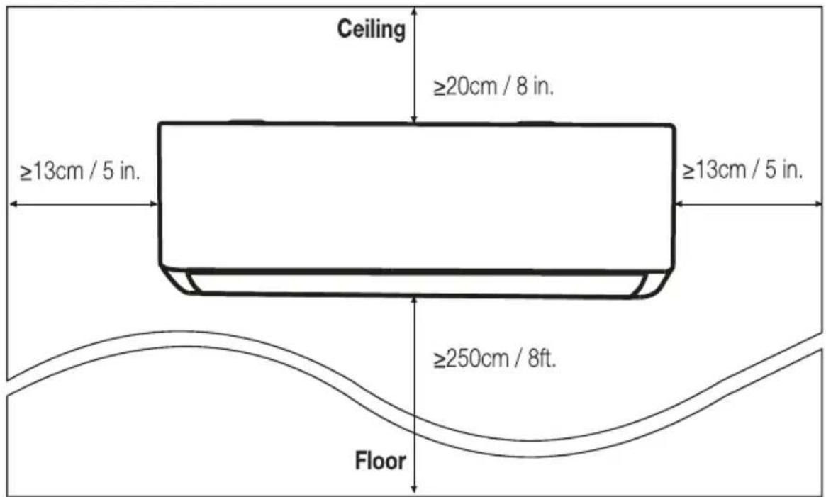
1.1 Ensure the installation complies with the installation minimum dimensions (defined below) and meets the minimum and maximum connecting piping length and maximum change in elevation as defined in the System Requirements section.
1.2 Air inlet and outlet will be clear of obstructions, ensuring proper airflow throughout the room.
1.3 Condensate can be easily and safely drained.
1.4 All connections can be easily made to outdoor unit.
1.5 Indoor unit is out of reach of children.
1.6 A mounting wall strong enough to withstand four times the full weight and vibration of the unit.
1.7 Filter can be easily accessed for cleaning.
1.8 Leave enough free space to allow access for routine maintenance.
1.9 Install at least 10 ft (3 m) away from the antenna of TV set or radio. Operation of the air conditioner may interfere with radio or TV reception in areas where reception is weak. An amplifier may be required for the affected device.
1.10 Do not install in a laundry room or by a swimming pool due to the corrosive environment.
1.11 For ETL certification area, Caution: Mount with the lowest moving parts at least 8 ft (2.4 m) above floor or grade level.
Minimum Indoor Clearances
Step2: Install Mounting Plate
2.1 Take the mounting plate from the back of indoor unit.
2.2 Ensure to meet the minimum installation dimension requirements as step 1, according to the size of mounting plate, determine the
position and stick the mounting plate close to the wall.
2.3 Adjust the mounting plate to a horizontal state with a spirit level, then mark out the screw hole positions on the wall.
7 INDOOR UNIT INSTALLATION
2.4 Put down the mounting plate and drill holes in the marked positions with drill.
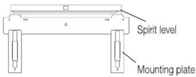
2.5 Insert expansion rubber plugs into the holes, then hang the mounting plate and fix it with screws.
Reference screw positions


Note:
(I) Make sure the mounting plate is firm enough and flat against the wall after installation.
(II) This figure shown may be different from the actual object, please take the latter as the standard.
Step3: Drill Wall Hole
A hole in the wall should be drilled for refrigerant piping, the drainage pipe, and connecting cables.
3.1 Determine the location of wall hole base on the position of mounting plate.
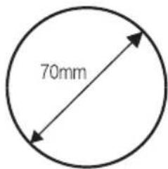
3.2 The hole should be have a 70mm diameter at least and a small oblique angle to facilitate drainage.
3.3 Drill the wall hole with 70mm core drill and with small oblique angle lower than the indoor end about 5mm to 10mm.
Wall sleeve Cover
(Optional)
Indoor
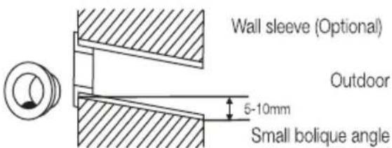
3.4 Place the wall sleeve and wall sleeve cover (both are optional parts) to protect the connection parts.

Caution:
When drill the wall hole, maker sure to avoid wires, plumbing and other sensitive components.
Step4: Connecting Refrigerant Pipe
4.1 According to the wall hole position, select the appropriate piping mode. There are three optional piping modes for indoor units as shown in the figure below: In Piping Mode 1 or Piping Mode 3, a notch should be made by using scissors to cut the plastic sheet of piping outlet and cable outlet on the corresponding side of the indoor unit.

Note: When cutting off the plastic sheet at the outlet, the cut should be trimmed to smooth.
7 INDOOR UNIT INSTALLATION

4.2 Bending the connecting pipes with the port facing up as shown in the figure.
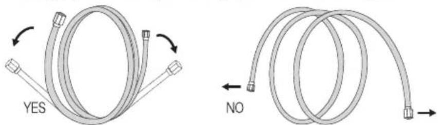
4.3 Take off the plastic cover in the pipe ports and take off the protective cover on the end of piping connectors.
4.4 Check whether there is any sundry on the port of the connecting pipe and make ensure the port is clean.
4.5 After align the center, rotate the nut of the connecting pipe to tighten the nut as tightly as possible by hand.
4.6 Use a torque wrench to tighten it according to the torque values in the torque requirements table; (Refer to the torque requirements table on section INSTALLATION PRECAUTIONS)
4.7 Wrap the joint with the insulation pipe.
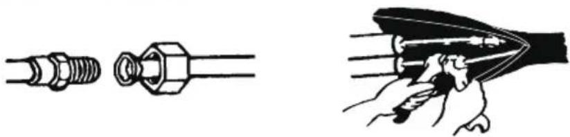

Note: For R32 refrigerant, the connector should be placed outdoors.

6
INDOOR UNIT INSTALLATION
Step5: Connect Drainage Hose
5.1 Adjust the drainage hose (if applicable) In some model, both sides of the indoor unit are provided with drainage ports, you can choose one of them to attach the drainage hose. And plug the unused drain port with the rubber attached in one of the ports.

Drainage ports

Step6: Connect Wiring
6.1 Choose the right cables size determined by the maximum operating current on the nameplate. (Check the cables size refer to section INSTALLATION PRECAUTIONS)
6.2 Open the front panel of indoor unit.
6.3 Use a screwdriver, open the electric control box cover, to reveal the terminal block.
6.4 Unscrew the cable clamp.

5.2 Connect the drainage hose to the drainage port, ensure the joint is firm and the sealing effect is good.
5.3 Wrap the joint firmly with teflon tape to ensure no leaks.

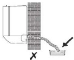
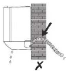
Note: Make sure there is no twists or dents, and the pipes should be placed obliquely downward to avoid blockage, to ensure proper drainage.

6.5 Insert one end of the cable into the position of control box from the back of the right end of the indoor unit.
6.6 Connect the wires to corresponding terminal according to the wiring diagram on the electric control box cover. And make sure that they are well connected.
6.7 Screw the cable clamp to fasten the cables.
6.8 Reinstall the electric control box cover and front panel.

6
INDOOR UNIT INSTALLATION
Step7: Wrap Piping and Cable
After the refrigerant pipes, connecting wires and drainage hose are all installed, in order to save space, protect and insulate them, it must be bundle with insulating tape before passing them through the wall hole.
7.1 Arrange the pipes, cables and drainage hose well as the following picture.


Note:
(I) Make sure the drainage hose is at the bottom.
(II) Avoid crossing and bending of parts.
7.2 Using the insulating tape wrap the refrigerant pipes, connecting wires and drainage hose together tightly.

Step8: Mount Indoor Unit
8.1 Slowly pass the refrigerant pipes, connecting wires and drainage hose wrapped bundle through the wall hole.
8.2 Hook the top of indoor unit on the mounting plate.
8.3 Apply slight pressure to the left and right sides of the indoor unit, make sure the indoor unit is hooked firmly.
8.4 Push down the bottom of indoor unit to let the snaps onto the hooks of the mounting plate, and make sure it is hooked firmly.
Sometimes, if the refrigerant pips were already embedded in the wall, or if you want to connecting the pips and wires on the wall, do as below:
(I) Gab both ends of the bottom plate, apply a little outward force to take off the bottom plate.
(II) Hook the top of the indoor unit on the mounting plate without piping and wiring.
(III) Lift the indoor unit opposite the wall, unfold the bracket on the mounting plate, and use this bracket to prop up the indoor unit, there will be a big space for operation.
(IV) Do the refrigerant piping, wiring, connect drainage hose, and wrap them as Step 4 to 7.
(V) Replace the bracket of mounting plate.
(VI) Push down the bottom of indoor unit to let the snaps onto the bottom hooks of the mounting plate, and make sure it is hooked firmly.
(VII) Replace the bottom plate of the indoor unit.

7 OUTDOOR UNIT INSTALLATION
Step1: Select Installation Location
Select a site that allows for the following:
1.1 Do not install the outdoor unit near sources of heat, steam or flammable gas.
1.2 Do not install the unit in too windy or dusty places.
1.3 Do not install the unit where people often pass. Select a place where the air discharge and operating sound will not disturb the neighbors.
1.4 Avoid installing the unit where it will be exposed to direct sunlight (other wise use a protection, if necessary, that should not interfere with the air flow).
1.5 Reserve the spaces as shown in the picture for the air to circulate freely.
1.6 Install the outdoor unit in a safe and solid place.
1.7 If the outdoor unit is subject to vibration, place rubber blankets onto the feet of the unit.

Step2: Install Drainage Hose
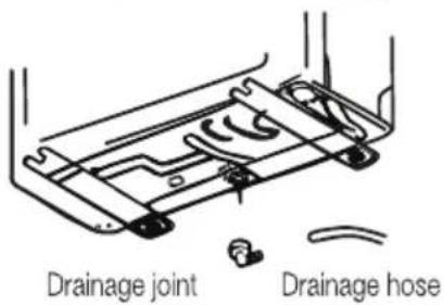
2.1 This step only for heating pump models.
2.2 Insert the drainage joint to the hole at the bottom of the outdoor unit.
2.3 Connect the drainage hose to the joint and make the connection well enough.
Step3: Fix Outdoor Unit
3.1 According to the outdoor unit installation dimensions to mark the installation position for expansion bolts.
3.2 Drill holes and clean the concrete dust and place the bolts.
3.3 If applicable install 4 rubber blankets on the hole before place the outdoor unit (Optional). This will reduce vibrations and noise.
3.4 Place the outdoor unit base on the bolts and pre-drilled holes.
3.5 Use wrench to fix the outdoor unit firmly with bolts.
7 OUTDOOR UNIT INSTALLATION

Install 4 rubber blankets (Optional)

Note: The outdoor unit can be fixed on a wall-mounting bracket.
Follow the instruction of the wall-mounting bracket to fix the wall-mounting bracket on the wall, and then fasten the outdoor unit on it and keep it horizontal.
The wall-mounting bracket must be able to support at least 4 times of the weight of outdoor unit.
Step4: Install Wiring
4.1 Use a phillips screwdriver to unscrew wiring cover, grasp and press it down gently to take it down.
4.2 Unscrew the cable clamp and take it down.
4.3 According to the wiring diagram pasted inside the wiring cover, connect the connecting wires to the corresponding terminals, and ensure all connections are firmly and securely.
4.4 Reinstall the cable clamp and wiring cover.

Note: When connecting the wires of indoor and outdoor units, the power should be cut off.


Wiring diagram
Step5: Connecting Refrigerant Pipe
5.1 Unscrews the valve cover, grasp and press it down gently to take it down (if the valve cover is applicable).
5.2 Remove the protective caps from the end of valves.
5.3 Take off the plastic cover in the pipe ports and check whether there is any sundry on the port of the connecting pipe and make ensure the port is clean.
5.4 After align the center, rotate the flare nut of the connecting pipe to tighten the nut as tightly as possible by hand.
5.5 Use a spanner hold the body of the valve and use a torque wrench to tighten the flare nut according to the torque values in the torque requirements table. (Refer to the torque requirements table on section INSTALLATION PRECAUTIONS)
7 OUTDOOR UNIT INSTALLATION

Take down the valve cover
connection pipes


Step6: Vacuum Pumping
6.1 Use a spanner to take down the protective caps from the service port, low pressure valve and high pressure valve of the outdoor unit.
6.2 Connect the pressure hose of manifold gauge to the service port on the outdoor unit low pressure valve.
6.3 Connect the charge hose from the manifold gauge to the vacuum pump.
6.4 Open the low pressure valve of the manifold gauge and close the high pressure valve.
6.5 Turn on the vacuum pump to vacuum the system.
6.6 The vacuum time should not be less than 15 minutes, or make sure the compound gauge indicates -0.1 MPa (-76 cmHg)
6.7 Close the low pressure valve of the manifold gauge and turn off the vacuum.
6.8 Hold the pressure for 5 minutes, make sure that the rebound of compound gauge pointer does not exceed 0.005 MPa.
6.9 Open the low pressure valve counterclockwise for 1/4 turn with hexagonal wrench to let a little refrigerant fill in the system, and close the low pressure valve after 5 seconds and quickly remove the pressure hose.
6.10 Check all indoor and outdoor joints for leakage with soapy water or leak detector.
6.11 Fully open the low pressure valve and high pressure valve of the outdoor unit with hexagonal wrench.
6.12 Reinstall the protective caps of the service port, low pressure valve and high pressure valve of the outdoor unit.
6.13 Reinstall the valve cover.
7 OUTDOOR UNIT INSTALLATION

8 TEST OPERATION
Inspections Before Test Run
Do the following checks before test run.
| Description | Inspection method |
| Electrical safety inspection | Check whether the power supply voltage complies with specification.Check whether there is any wrong or missing connection between the power lines, signal line and earth wires.Check whether the earth resistance and insulation resistance comply with requirements. |
| Installation safety inspection | Confirm the direction and smoothness of drainage pipe.Confirm that the joint of refrigerant pipe is installed completely.Confirm the safety of outdoor unit, mounting plate and indoor unit installation.Confirm that the valves are fully open.Confirm that there are no foreign objects or tools left inside the unit.Complete installation of indoor unit air inlet grille and panel. |
| Refrigerant leakage detection | The piping joint, the connector of the two valves of the outdoor unit, the valve spool, the welding port, etc., where leakage may occur.Foam detection method:Apply soapy water or foam evenly on the parts where leakage may occur, and observe whether bubbles appear or not, if not, it indicates that the leakage detection result is safe.Leak detector method:Use a professional leak detector and read the instruction of operation, detect at the position where leakage may occur.The duration of leak detection for each position should last for 3 minutes or more;If the test result shows that there is leakage, the nut should be tightened and tested again until there is no leakage;After the leak detection is completed, wrap the exposed pipe connector of indoor unit with thermal insulation material and wrap with insulation tape. |
8 TEST OPERATION
Test Run Instruction
- Turn on the power supply.
- Press the ON/OFF button on the remote controller to turn on the air conditioner.
- Press the Mode button to switch the mode COOL and HEAT.
In each mode set as below:
COOL-Set the lowest temperature
HEAT-Set the highest temperature
- Run about 8 minutes in each mode and check all functions are properly run and respond the remote controller. Functions check as recommended:
4.1 If the outlet air temperature respond the cool and heat mode
4.2 If the water drains properly from the drainage hose
4.3 If the Louver and deflectors (optional) rotate properly
-
Observe the test run state of the air conditioner at least 30 minutes.
-
After the successfully test run, return the normal setting and press ON/OFF button on the remote controller to turn off the unit.
-
Inform the user to read this manual carefully before use, and demonstrate to the user how to use the air conditioner, the necessary knowledge for service and maintenance, and the reminder for storage of accessories.

Note: If the ambient temperature is excess the range refer to section OPERATION INSTRUCTIONS, and it can not run COOL or HEAT mode, lift the front panel and refer to the emergency button operation to run the COOL and HEAT mode.
9
MAINTENANCE
| Warning | When cleaning, you must shut down the machine and cut off the power supply for more than 5 minutes.Under no circumstances should the air conditioner be flushed with water.Volatile liquid (e.g. thinner or gasoline) will damage the air conditioner, so only use soft dry cloth or wet cloth dipped with neutral detergent to clean the air conditioner.Pay attention to cleaning the filter screen regularly to avoid dust covering which will affect the filter screen effect. When the operating environment is dusty, the cleaning frequency should be increased appropriately.After removing the filter screen, do not touch the fins of the indoor unit to avoid scratching. |
| Clean the unit | 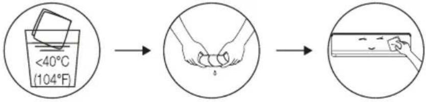 Wring it dryGentle wipe the unit surfaceTip: Wipe frequently to keep air conditioner clean and good appearance. Wring it dryGentle wipe the unit surfaceTip: Wipe frequently to keep air conditioner clean and good appearance. |
| Disassembly and assembly of filter | Grasp the raised handle on the filter by hand, and then pull the filter out in the direction deviating from the unit, so that the upper edge of the filter is separated from the unit.The filter can be removed by lifting the filter upwards.When installing the filter, first insert the lower end of the filter screen into the corresponding position of the unit, and then squeeze the upper end of the filter into the corresponding buckling position of the unit body.Handle |
| Clean the filter |  → →   Take out the filter from the unit Clean the filter with soapy water and air dry it Replace the filterTip: When you find accumulated dust in the filter, please clean the filter in time to ensure the clean, healthy and efficient operation inside the air conditioner. Take out the filter from the unit Clean the filter with soapy water and air dry it Replace the filterTip: When you find accumulated dust in the filter, please clean the filter in time to ensure the clean, healthy and efficient operation inside the air conditioner. |
| Cleaning of inner air duct | First, loosen the knob on the middle of louver and bend the louver outwards to take it out.Then, grasp both sides of bottom plate push downwards to take down the bottom plate.Finally, loosen the buckle of deflector assembly with your thumb and take it out.Wipe the air duct and fan assembly with a clean and wrung wet rag.Clean the removed parts with soapy water and air dry it.After cleaning, restore the removed parts in turn. Deflector assembly Deflector assembly  + +  Bottom plate Bottom plate |
| Service and maintenance | When the air conditioner is not in use for a long time, do the following work: Take out the batteries of the remote controller and disconnect the power supply of the air conditioner.When starting to use after long-term shutdown:Clean the unit and filter screen;Check whether there are obstacles at the air inlet and outlet of indoor and outdoor units;Check whether the drain pipe is unobstructed;Install the batteries of the remote controller and check whether the power is on. |
10 TROUBLESHOOTING
| MALFUNCTION | POSSIBLE CAUSES |
| The appliance does not operate | Power failure/plug pulled out. |
| Damaged indoor/outdoor unit fan motor. | |
| Faulty compressor thermomagnetic circuit breaker. | |
| Faulty protective device or fuses. | |
| Loose connections or plug pulled out. | |
| It sometimes stops operating to protect the appliance. | |
| Voltage higher or lower than the voltage range. | |
| Active TIMER-ON function. | |
| Damaged electronic control board. | |
| Strange odor | Dirty air filter. |
| Noise of running water | Back flow of liquid in the refrigerant circulation. |
| A fine mist comes from the air outlet | This occurs when the air in the room becomes very cold, for example in the “COOLING” or “DEHUMIDIFYING/DRY” modes. |
| A strange noise can be heard | This noise is made by the expansion or contraction of the front panel due to variations in temperature and does not indicate a problem. |
| Insufficient airflow, either hot or cold | Unsuitable temperature setting. |
| Obstructed air conditioner intakes and outlets. | |
| Dirty air filter. | |
| Fan speed set at minimum. | |
| Other sources of heat in the room. | |
| No refrigerant. | |
| The appliance does not respond to commands | Remote control is not close enough to indoor unit. |
| The batteries of remote control need to be replaced. | |
| Obstacles between remote control and signal receiver in indoor unit. | |
| The display is off | Active DISPLAY function. |
| Power failure. | |
| Switch off the air conditioner immediately and cut off the power supply in the event of: | Strange noises during operation. |
| Faulty electronic control board. | |
| Faulty fuses or switches. | |
| Spraying water or objects inside the appliance. | |
| Overheated cables or plugs. | |
| Very strong smells coming from the appliance. |
10 TROUBLESHOOTING
ERROR CODE ON THE DISPLAY
In case of error, the display on the indoor unit shown the following error codes:
| Display | Description of the trouble |
| E1 | Indoor room temperature sensor fault |
| E2 | Indoor pipe temperature sensor fault |
| E3 | Outdoor pipe temperature sensor fault |
| E4 | Refrigerant system leakage or fault |
| E6 | Malfunction of indoor fan motor |
| E7 | Outdoor ambient temperature sensor fault |
| E0 | Indoor and outdoor communication fault |
| E8 | Outdoor discharge temperature sensor fault |
| E9 | Outdoor IPM module fault |
| ER | Outdoor current detect fault |
| EE | Outdoor PCB EEPROM fault |
| EF | Outdoor fan motor fault |
| EH | Outdoor suction temperature sensor fault |
11 European disposal guideline
This appliance contains refrigerant and other potentially hazardous materials. When disposing of this appliance, the law requires special collection and treatment, Do not dispose of this product as household waste or unsorted municipal waste.
When disposing of this appliance, you have the following options:
- Dispose of the appliance at designated municipal electronic waste collection facility.
- When buying a new appliance, the retailer will take back the old appliance free of charge.
- The manufacturer will take back the old appliance free of charge.
- Sell the appliance to certified scrap metal dealers.

Special notice: Disposing of this appliance in the forest or other natural surroundings endangers your health and is bad for the environment. Hazardous substances may leak into the ground water and enter the food chain.
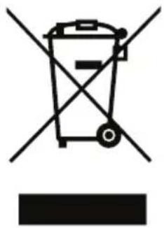
This symbol indicates that this product shall not be disposed with other household wastes at the end of its service life. Used device must be returned to official collection point for recycling of electrical and electronic devices. To find these collection systems please contact to your local authorities or retailer where the product was purchased. Each household performs important role in recovering and recycling of old appliance. Appropriate disposal of used appliance helps prevent potential negative consequences for the environment and human health.
12 Installation instructions
12.1 F-Gas instruction
This product contains fluorinated greenhouse gases.
The fluorinated greenhouse gases are contained in hermetically sealed equipment.
Installs, services, maintains, repairs, checks for leaks or decommissions equipment and product recycling should be carried out by natural persons that hold relevant certificates.
If the system has a leakage detection system installed, leakage checks should be performed at least every 12 months, make sure system operate properly.
If product must be performed leakage checks, it should specify Inspection cycle, establish and save records of leakage checks.

Note: For hermetically sealed equipment, local air conditioner, window air conditioner and dehumidifier, if CO2 equivalent of fluorinated greenhouse gases is less than 10 tonnes, it should not perform leakage checks.
13 Specifications
| Model name | Indoor unit | BAVOT 090 NG BAVOT 120 NG BAVOT 180 NG | BAVOT 240 NG | ||
| Outdoor unit | BAVOT 091 NG BAVOT 121 NG BAVOT 181 NG | BAVOT 241 NG | |||
| Refrigerant | R32 R32 R32 R32 | ||||
| Total Refrigerant Amount (g) | 290 | 400 630 790 | |||
| Anti-Electric | Class I Class I Class I Class I | ||||
| Climate Class | T1 T1 T1 T1 | ||||
| Heating Type | Cooling Only Cooling Only Cooling Only Cooling Only | Only | |||
| Power Supply Connection | Indoor Indoor Indoor Indoor | ||||
| Cooling Capacity (Btu/h) [T1] | 9000 12000 18000 24000 | ||||
| Cooling Capacity (Btu/h) [T3] | / / / / | ||||
| Cooling Capacity (W) [T1] | 2638 35175275 | 7034 | |||
| Cooling Capacity (W) [T3] | / / / / | ||||
| Heating Capacity (Btu/h) | / / / / | ||||
| Heating Capacity (W) | / / / / | ||||
| Energy Efficiency Cooling [T1] | 3.21 | 2.61 3.01 3.21 | |||
| Energy Efficiency Cooling [T3] | / / / / | ||||
| Energy Efficiency Heating (W/W) | / / / / | ||||
| Energy Level-Cooling | / / / / | ||||
| Energy Level-Heating | / / / / | ||||
| Annual Energy Consumption (kwh) | 288 427 613 767 | ||||
| Power of Electric Heater (W) | / / / / | ||||
| Cooling Power Input (W) [T1] | 822 1348 1752 | 2191 | |||
| Cooling Power Input (W) [T3] | / / / / | ||||
| Heating Power Input (W) | / / / / | ||||
| Voltage/Frequency (V/Hz) | 1Ph~ / 220-240V~ / 50Hz | 1Ph~ / 220-240V~ / 50Hz | 1Ph~ / 220-240V~ / 50Hz | 1Ph~ / 220-240V~ / 50Hz | |
| Cooling Running Current (A) [T1] | 3.9 6.2 8.7 10.7 | ||||
| Cooling Running Current (A) [T3] | / / / / | ||||
| Heating Running Current (A) | / / / / | ||||
| Noise Pressure Level - Indoor Unit (dBA) | 50 | 49 | 56 | 59 | |
| Noise Pressure Level - Outdoor Unit (dBA) | 61 | 64 | 63 | 64 | |
| Air flow volume ( m3/h ) | 530 | 450 810 1200 | |||
| Rated Power Input-EN 60335(W) | 1250 | 1500 2300 2650 | |||
| Rated Current Input-EN 60335(A) | 6.0 7.0 12.0 13.0 | ||||
| Indoor unit Resistance Class | / / / / | ||||
| Outdoor unit Resistance Class | IPX4 IPX4 | IPX4 IPX4 | |||
| High Pressure Pipe Diameter (mm) | Φ6 | Φ6 | Φ6 | Φ6 | |
| Low Pressuer Pipe Diameter (mm) | Φ9.52 Φ9.52 | Φ12 Φ12 | |||
| Max. elevation (m) | 5 | 5 | 5 | 5 | |
| Max. pipe length (m) | 15 | 15 | 15 | 15 | |
| Additional Gas Quantity (g/m) | 20 | 20 | 30 | 30 | |
| Power Supply Cord specification (mm2) | 3*1.0 | 3*1.0 | 3*1.5 | 3*1.5 | |
| Indoor & Outdoor Connection Cord (mm2) | 4*1.0 | 4*1.0 | 4*1.5 | 4*1.5 | |
| Indoor Unit (WxHxD) mm | 790×275×192 | 790×275×192 | 920×306×195 | 1100×333×222 | |
| Outdoor Unit (WxHxD) mm | 670×455×230 | 675×455×235 | 740×545×262 | 795×600×295 | |
| Indoor Unit Net Weight (kg) | 8.0 8.5 10.5 14.5 | ||||
| Outdoor Unit Net Weight (kg) | 19.0 | 19.0 25.0 30.0 | |||
Note:
-
Specifications are standard values calculated based on rated operating conditions, They will vary in difference work condition.
-
T1 Rated Cooling value are tested under 27/19 (In.) 35/24 (Out.) condition
-
T3 Rated Cooling value are tested under 29/19 (In.) 46/24 (Out.) condition. (For T3 Climate model only)
-
Rated Heating value are tested under 7/6 (In.) 20/15 (Out.) condition. (For Heat pump model only)
-
Our company has quick technical impairments. There will be prior notice for any change of technical data. Please read nameplate on the air-conditioner.
13 Specifications

Note:
- Specifications are standard values calculated based on rated operating conditions, They will vary in difference work condition.
- Rated cooling values at T1 condition are calculated under 27/19 (In.) 35/24 (Out.) condition
- Rated cooling values at T3 are calculated under 29/19 (In.) 46/24 (Out.) condition.
- Rated heating value are calculated under 7/6 (In.) 20/15 (Out.) condition. (For Heat pump model only)


- Split type air conditioner
- Contents
- Please read this user manual first
- Dear customer
- Meanings of the symbols
- 1 Safety precautions 6
- 2 Name of parts 10
- 3 Remote control 12
- 1 Safety precautions
- Safety rules and recommendations for the installer
- Safety rules and prohibitions
- 2 Name of parts
- Warning
- 3 Remote control
- Remote control display
- Meaning of symbols on the liquid crystal display
- Replacement of batteries
- Note
- 3.1 Cooling mode
- Cool
- 3.2 FAN mode (not fan button)
- Fan
- 3.3 DRY mode
- Dry
- 3.4 Auto mode
- Auto
- 3.5 Heating mode
- Heat
- 3.6 FAN speed function (fan button)
- 3.7 Child-lock function
- 3.8 Timer function - timer on
- 3.9 Turbo function
- Turbo
- 3.10 Swing function
- 3.11 Sleep function
- 3.12 I feel function
- 3.13 ECO function (optional feature)
- Eco
- 3.14 GEN function
- Gen
- 3.15 Display function (indoor display)
- Display
- 3.16 Goclean(optional feature)
- Clean
- 3.17 8°C heating function (optional)
- 3.18 Gentle wind function (optional)
- 3.19 Health function (optional)
- 3.20 Wifi reset (optional)
- 4 Operation instructions
- Characteristics of heating operation (applicable to heating pump)
- Preheating
- Defrosting
- Emergency button
- 5 Installation precautions
- 6 Indoor unit installation
- Step1: select installation location
- Step2: install mounting plate
- 7 Indoor unit installation
- Step3: drill wall hole
- Caution
- Step4: connecting refrigerant pipe
- 6
- Indoor unit installation
- Step5: connect drainage hose
- Step6: connect wiring
- Step7: wrap piping and cable
- Step8: mount indoor unit
- Sometimes, if the refrigerant pips were already embedded in the wall, or if you want to connecting the pips and wires on the wall, do as below
- 7 Outdoor unit installation
- Step2: install drainage hose
- Step3: fix outdoor unit
- Step4: install wiring
- Step5: connecting refrigerant pipe
- Step6: vacuum pumping
- 8 Test operation
- Inspections before test run
- Test run instruction
- 9
- Maintenance
- 10 Troubleshooting
- Error code on the display
- 11 European disposal guideline
- 12 Installation instructions
- 12.1 F-gas instruction
- 13 Specifications
Prekės ženklas : BEKO
Modelis : BAVOT 180 NG
Kategorija : Oro kondicionierius