CS 1SN-RF RGB - Mikrofonas Clockaudio - Nemokama naudojimo instrukcija
Raskite įrenginio instrukciją nemokamai CS 1SN-RF RGB Clockaudio PDF formatu.

Naudotojų klausimai apie CS 1SN-RF RGB Clockaudio
0 klausimas apie šį prietaisą. Atsakykite į tas, kurias žinote, arba užduokite savo.
Užduokite naują klausimą apie šį prietaisą
Atsisiųskite instrukciją savo Mikrofonas PDF formatu nemokamai! Raskite savo instrukciją CS 1SN-RF RGB - Clockaudio ir vėl perimkite savo elektroninį įrenginį. Šiame puslapyje skelbiami visi dokumentai, reikalingi jūsų įrenginio naudojimui. CS 1SN-RF RGB prekės ženklo Clockaudio.
NAUDOJIMO INSTRUKCIJA CS 1SN-RF RGB Clockaudio
The CS 1S-RF is a boundary layer microphone with a half cardioid polar pattern. The microphone is fitted with a RGB electronic capacitive touch sensitive switch designed to be used for remote switching. Available in black Nextel (CS 1S-RF RGB) or satin nickel (CS 1SN-RF RGB).
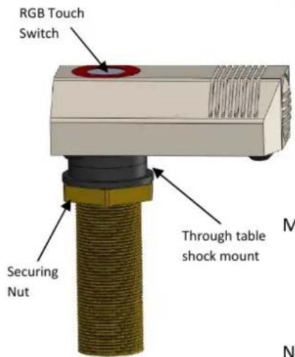
Switch Features
- RGB electronic capacitive touch switch facilitating click/pop free switching.
- Programmable via a DSP to display up to seven colour combinations and operate in PTT, PTM or Latching modes.
- Works only in conjunction with supplied TS-C1 touch switch controller that accepts 6 way colour coded ribbon cable from RGB LEDs, a 2 way phoenix connector for connection to the reed switch and TS-OUT for connection to a DSP via a CAT-5 Ethernet cable.
Microphone features
• Half cardioid polar pattern.
• Balanced output that is immune to RF artifacts.
• Power requirements 9-48V phantom power.
• Cable 2m 2 core + screen.
Note: Microphone muting is controlled via DSP and activation of touch switch.
natural_image
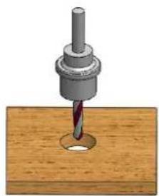
3D illustration of a drill bit on a wooden surface (no text or symbols)Fig A
Installation guide
1) Pre-drill a 24mm/0.94" hole through the table. See fig A.
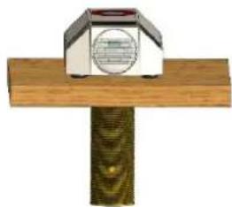
2) After removing the Nut and one shock mount push fit the CS 1S-RF through the table. See fig B.
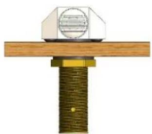
3) Replace shock mount and hand tighten nut to secure the CS 1S-RF onto the table. See fig C.
4) Audio wiring connections:
Red phase +
White phase –
Screen/shield—ground
Note: microphone screen and TS-C1 ground must have a common ground connection.
natural_image
Mechanical assembly diagram showing a bolted joint with a mounted component (no text or symbols visible)Fig C
5) TS-C1's TS-OUT wiring for connection to DSP:
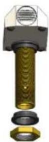
Fig B
| Pin number | Function |
| 1 | Switch (Low indicating contacts closed on RS-IN) |
| 2 | Red LED (pulled low to illuminate) |
| 3 | Ground |
| 4 | +12V DC |
| 5 | Touch Switch Activated |
| 6 | Green LED (pulled low to illuminate) |
| 7 | Blue LED (pulled low to illuminate) |
| 8 | No connection |
natural_image
Simple illustration of a mailbox mounted on a wooden post (no text or symbols visible)6) Affix TS-C1 under table.