700 ABC - Biuro kėdė Eurovema - Nemokama naudojimo instrukcija
Raskite įrenginio instrukciją nemokamai 700 ABC Eurovema PDF formatu.

Naudotojų klausimai apie 700 ABC Eurovema
0 klausimas apie šį prietaisą. Atsakykite į tas, kurias žinote, arba užduokite savo.
Užduokite naują klausimą apie šį prietaisą
Atsisiųskite instrukciją savo Biuro kėdė PDF formatu nemokamai! Raskite savo instrukciją 700 ABC - Eurovema ir vėl perimkite savo elektroninį įrenginį. Šiame puslapyje skelbiami visi dokumentai, reikalingi jūsų įrenginio naudojimui. 700 ABC prekės ženklo Eurovema.
NAUDOJIMO INSTRUKCIJA 700 ABC Eurovema
bruksanvisning / manual

EUROFLEX
700 ABC
natural_image
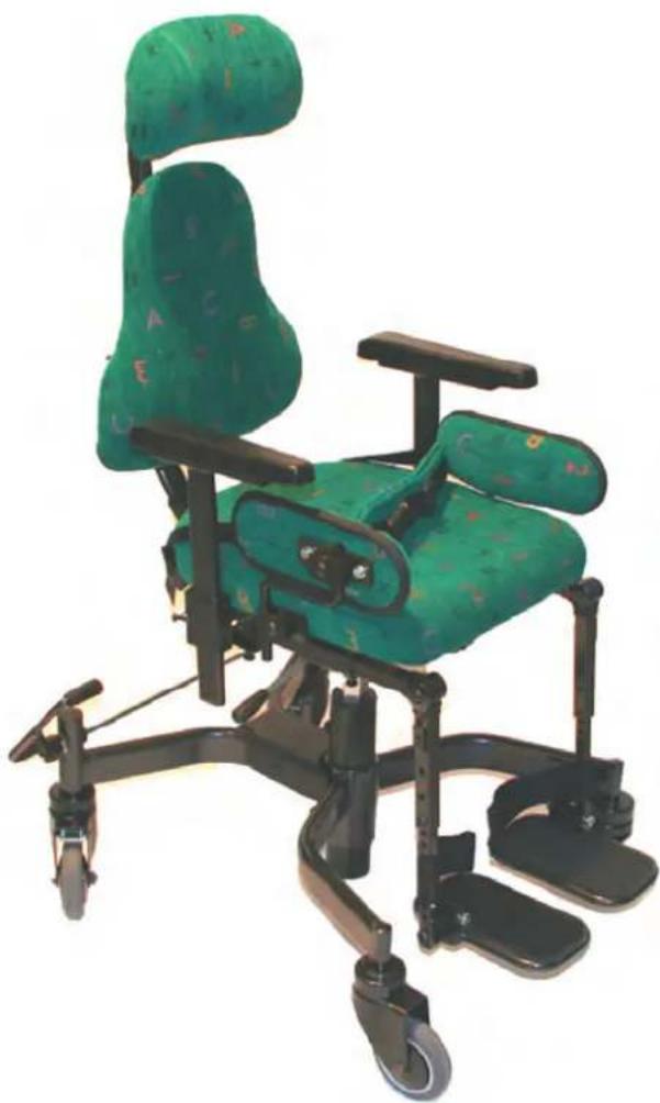
Green and black children's mobility chair with adjustable legs and wheels (no text or symbols visible)CE
Eurovema
Creates mobility and ergonomics.
svenska english
INNEHÅLLSFÖRTECKNING CONTENT
| S. | P. | ||
| Inledning 2 Introduction | 2 | ||
| Kontakt | 2 | Contact | 2 |
| Säkerhetsföreskrifter 3 Safety 3 | |||
| Översikt | 4 Over view | 4 | |
| Broms 4 Brakes | 4 | ||
| Sitsinställningar - manuella 5-10 | Seat adjustments - manual | 5-10 | |
| Sitsinställningar - elektrisk | 10-11 | Seat adjustments - electri | 10-11 |
| Laddning av batterier | 11 | Charging of batteries | 11 |
| Skötselanvisningar | 12 | Maintenance | 12 |
| Service | 13 | Service | 13 |
| Garanti | 13 | Warranty | 13 |
| CE- märkning | 13 | CE - label | 13 |
| Tekniska fakta | 14 | Technical facts | 14 |
svenska english
INLEDNING INTRODUCTION
ABC är ett sittsystem utvecklat för barn som är uppbyggd kring ett fl exibelt byggsystem med ett brett tillbehörsprogram. Sittsytemet kan monteras på olika typer av chassin för olika behov. Som t.ex.700 ABC som är en arbetsstol eller Minifl ex 500 ABC som är en elrullstol för inomhusbruk. Kan även monteras på vår elrullstol Flexmobil 600 eller på inomhusunderredet från Alvema. Läs igenom bruksanvisningen noga för att kunna tillgodogöra er sitsen alla möjligheter. ABC is a seat system developed for children that has been built around a fl exible construction system with a broad accessory programme. The seat system can be fi tted to different types of chassis for different needs. Like the 700 ABC, which is a work chair, or Minifl ex 500 ABC, which is an electric wheelchair for indoor use. It can be also be fi tted to our Flex-mobil 600 electric wheelchair or to the indoor undercarriage from Alvema. Read the manual carefully so you can make the most of all the chairs' possibilities
svenska english
KONTAKT CONTACT
Har ni frågor eller behöver hjälp med er produkt kontaktas i första hand den lokala leverantören (Hjälpmedelscentral).
För att komma i kontakt med tillverkaren se info nedan:
Eurovema AB
Tel: 0371-39 01 00
Fax: 0371-189 82
E-post: info@eurovema.se
Baldersvägen 38
332 35 GISLAVED
Hemsida: www.eurovema.se
If you have questions or need help with your product, please contact the local agent. To get in touch with the manufacturer see info below:
Eurovema AB
Tel:+46-371-39 01 00
Fax: +46-371-189 82
E-mail: info@eurovema.se
Baldersvägen 38
332 35 GISLAVED
SWEDEN
Web: www.eurovema.se
SÄKERHETSFÖRESKRIFTER
- Läs igenom bruksanvisningen noga innan stolen tas i bruk.
- Arbetsstolen är avsedd att användas på plant underlag i ett normalt inomhusklimat.
- Upptäcks skador eller förändringar i stolens funktion ska serviceinstans (hjälpmedelsleverantör) genast kontaktas.
- Används stolen mycket bör den lämnas in till serviceinstans för översyn regelbundet.
- Var noga med att dra åt skruvar, vred och reglage ordetligt efter utförd justering.
- Ge akt på om skruvar eller delar blir lösa eller glappa på rullstolen då det kan påverka säkerheten. Kontakta service instans.
- Service och underhåll bör utföras av utbildad personal.
- Endast originaldelar från Eurovema ska användas vid reparation.
- Överskrid inte angiven max. brukarvikt på stolen.
- Undvik kontakt med skadade eller läckande batterier Uttjänta batterier skall lämnas för återvinninç
SAFETY
- Carefully read the manual before using the wheel chair
- The work chair is designed to be used on even surface in normal indoor climate.
- Immediately contact service if damages or change in function of the chair is discovered.
- If the chair is used frequently it should have service regularly.
- Make sure to tighten all screws, knobs and levers after adjustments..
- Immediately contact service if damages or change in function of the chair is discovered.
- Service and maintenance should be performed by educated staff.
- Use only original parts from Eurovema at repair.
- Do not exceed maximum user weight.
- Avoid contact with a damage or leaking battery. Used batteries should be recycled.
svenska english
4
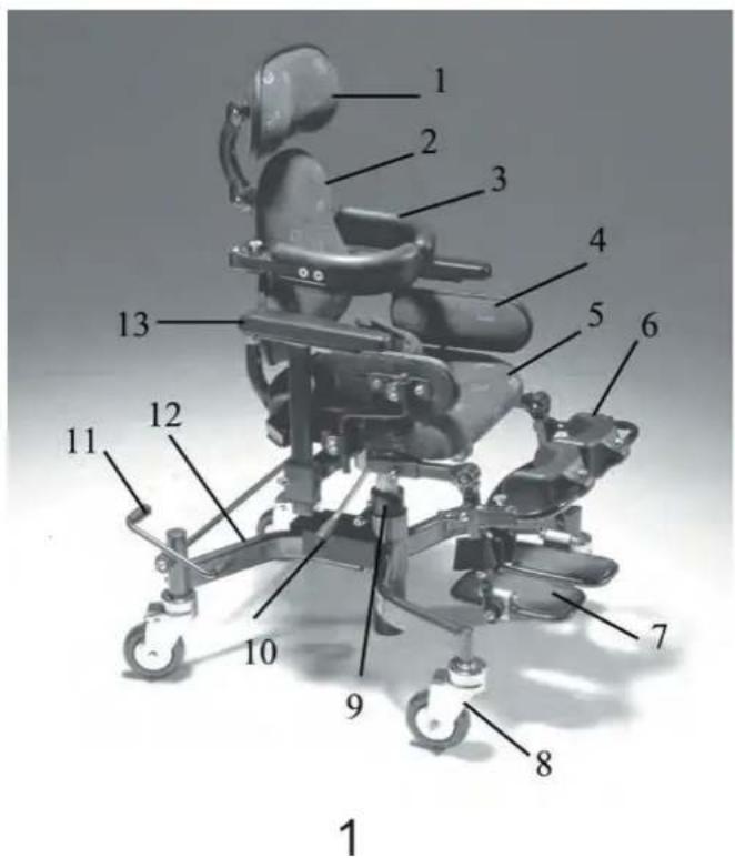
ÖVERSIKT (fi g 1
1) Nackstöd
2) Ryggstöd
3) Bålstöd
4) Sidostöd
5) Sits
6) Knästöd
7) Fotplattor
8) Länkhjul
9) Ställdon för sitslyft. El. eller gas.
10) Spak för justering sitshöjd. Gas.
11) Fotbroms
12) Chassi
svenska english
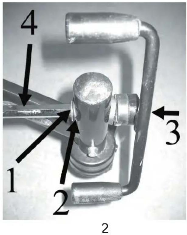
BROMS fig 2
Som standard levereras barnstolen ABC 700 med högermonterad fotbromspedal. Pedalen kan justeras i vinkel genom att lossa skruven (3). Drag åt skruven efteråt. Pedalen kan fl yttas till vänster sida enligt följande: - Lossa och tag bort skruven (3), pedal,bricka,packning. - Tag bort spårryttaren (1) och packningen (2) med kniv eller dyl. - Drag ut hela stängen (4) och sätt in den från andra hålllet.
- Trä på packningen och spärryttaren.- Justera pedalen till onskad vinkel med skruven (3). Verktyg: insexnyckel 5mm, kniv eller tång.
OVER VIEW (fi g 1
1) Neck rest
2) Back rest
3) Torso support
4) Side support
5) Seat
6) Knee rest
7) Foot rests
8) Castor
9) Actuator for seat lift. Electrical or gas.
10) Lever for adjustment of seat height.
11) Foot brake
12) Chassis
BRAKES (fi g 2
As standard the ABC 700 children's chair is delivered with a right-mounted foot brake pedal. The angle of the pedal can be adjusted by loosening the screw (3). Tighten the screw afterwards. The pedal can be moved to the left side as follows: - Unscrew and remove the screw (3), pedal, washer, gasket. - Remove the locking washer (1) and the gasket (2) with a knife or similar. - Pull out the entire rod (4) and insert it from the other side.
- Slip on the gasket and the locking washer - Adjust the pedal to the desired angle with the screw (3). Tools: Allen key 5mm, knife or pliers
4
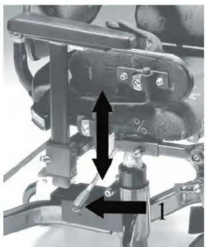
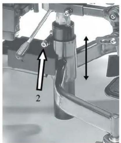
SITTHÖJD - GAS (fig 3-4)
Höjning av sitsen: Belasta ej sitsen. Drag i spaken till gaskolven (1) uppåt. Släpp spaken vid önskad sitthöjd
Sänkning av sitsen: Sitt i stolen eller belasta sitsen. Drag i spaken till gaskolven (1) uppåt. Släpp spaken vid önskad sitthöjd.
Gaskolven är som standard inställd på sitthöjdsintervallet 46 - 60 cm. (14 cm lyftverkan) För att nå lägre sitthöjd, 38 - 46 cm, väljes kort gaskolv. (8 cm lyftverkan). För högre sitthöjd kan gaskolvens läge i chassit ändras uppåt ca: 10 cm. Lossa skruv (2) och lyft hela sittenheten uppåt till önskat läge. Drag åt skruven hårt! Verktyg: insexnyckel 5 mm
svenska english
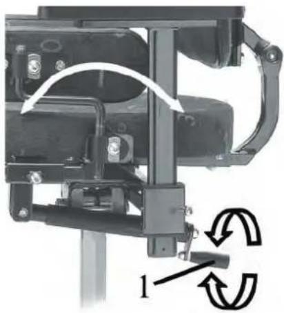
SITSVINKEL (fi g 5
Vinkling framåt:
- Medurs vevrörelse på reglaget (1). Max. 20° framåt.
Vinkling bakåt:
- Moturs vevrörelse på reglaget. (1). Max 20° bakåt.
SEAT HEIGHT - GAS (fi g 3-4
Raising the seat: Keep the seat free of weights. Pull the lever of the gas plunger (1) upwards. Release the lever at the desired seat height.
Lowering the seat: Sit on the seat or weigh it down. Pull the lever of the gas plunger (1) upwards. Release the lever at the desired seat height. The gas plunger is set at a seat height interval of 46 – 60 cm as standard. (14 cm lift action) To obtain a lower seat height, 38 – 46 cm, a short gas plunger is chosen. (8 cm lift action). For higher seat heights, the position of the chassis can be altered upwards approx. 10 cm Loosen the screw (2) and lift the entire seat unit upwards to the desired position. Tighten the screw tightly. Tool: Allen key 5 mm
SEAT ANGLE (fig 5)
Angling forward:
- Turn lever clockwise (1). Max. 20° forward.
Angling backward:
- Turn lever counter clockwise. (1). Max 20° backward.
natural_image
Mechanical assembly diagram showing mechanical components with directional arrows (no text or symbols)3
natural_image
Mechanical assembly diagram showing a valve and shaft with two directional arrows indicating motion (no text or symbols present)4
natural_image
Mechanical assembly diagram showing a frame with rotating components and directional arrows (no text or symbols)5
5
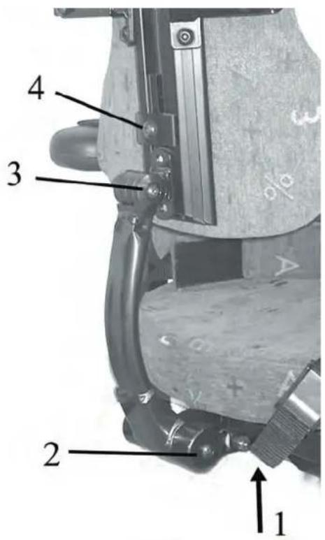
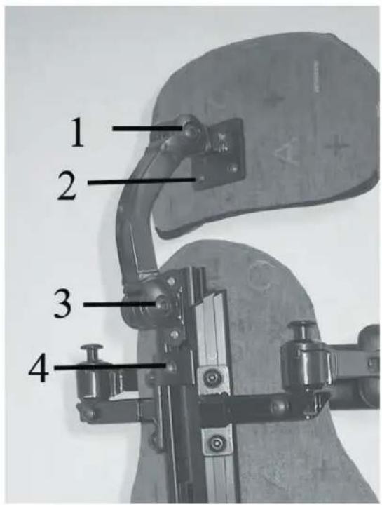
RYGGSTÖD - inställningar (fig 6
Vinkling av ryggen:- Lossa skruven (3). Ställ in önskad vinkel. Drag åt skruven.
Höjdinställning av ryggen: - Lossa skruven (4). Ställ in önskad höjd. Drag åt skruven.
Djupjustering av ryggen: - Grov justera djupet genom att ta bort skruven (1). Välj mellan 4 fasta lägen. - Finjustera djupet genom att lossa skruven (2). Dra åt skruvarna (1 och 2) när önskad vinkel uppnåtts. Skruva fast skruven. Verktyg: insexnyckel 5mm
svenska english
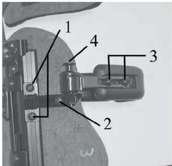
BÅLSTÖD - inställningar (fi g 7
Höjdjustering: Lossa skruvarna (1). Ställ in önskad höjd. Drag åt skruvarna.
Breddjustering: Lossa skruven (2). Ställ in önskad bredd. Drag åt skruven.
Djupjustering: Lossa skruvarna (3). Ställ in önskat djup. Drag åt skruvarna.
Fälla undan: Lyft den rödmarkerade knoppen rakt upp och vrid samtidigt bälstödet åt sidan. Verktyg: insexnyckel 5 mm)
BACK REST - adjustments (fig 6)
Angling of back rest - Loosen screw (3). Set the desired angle. Tighten the screw.
Setting the height of the back rest: - Loosen the screw (4). Set the desired height. Tighten the screw.
Setting the depth of the back rest: - Adjust the depth roughly by removing the screw (1). Choose among 4 fixed positions. - Finely adjust depth by loosening the screw (2). Tighten the screws (1 and 2) when the desired angle has been reached. Tighten the screw
Tool: Allen key 5mm
TORSO SUPPORT - adjustments (fig 7)
Height adjustment: Loosen the screws (1).
Set the desired height. Tighten the screws.
Width adjustment: Loosen the screw (2). Set the desired width. Tighten the screw.
Depth adjustment: Loosen the screws (3). Set the desired depth. Tighten the screws.
Fold back: Lift the knob marked red straight up and turn the torso support at the same time to the side.
Tool: Allen key 5 mm
6
7
NACKSTÖD - inställningar (fi g 8
Vinkel: Lossa skruvarna (1 och 3). Ställ in önskad vinkel. Drag åt skruvarna
Höjd: Lossa skruven (4). Lyft nackstödet till önskad höjd. Drag åt skruven.
Djup: Lossa skruven (3). Justera till önskat djup. Drag åt skruven.
För att justera nackkudden i sidled finns 4 extra islagmuttrar i linje med de synliga skruvarna (2). Verktyg: inexnyckel 5 mm
svenska english
SIDOSTÖD - inställningar (fi g 9
Vinkel och höjd: Lossa skruvarna (1 och 2). Ställ in önskad höjd och vinkel. Drag åt skruvarna.
Ökat stöd framåt: Lossa skruven (2) och lyft av sidostödskudden och vänd det. Skruva åt skruven.
Verktyg: insexnyckel 5 mm.
NECK REST - adjustments (fig 8)
Angle: Loosen the screws (1 and 3). Set the desired angle. Tighten the screws
Height: Loosen the screw (4). Lift the neck rest to the desired height. Tighten the screw.
Depth: Loosen the screw (3). Adjust to the desired depth. Tighten the screw.
To adjust the neck cushion sideways there are 4 extra pronged tee nuts in line with the visible screws (2). Tool: Allen key 5 mm
SIDE SUPPORT - adjustments (fig 9)
Angle and height Loosen the screws (1 and 2). Set the desired height and angle. Tighten the screws.
Added support forward: Loosen the screw (2) and lift off the side support cushion and turn it. Tighten the screw.
Tool: Allen key 5 mm
8
9
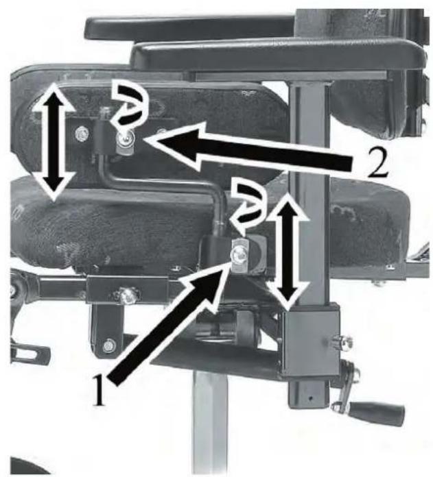
ARMSTÖD – intällningar (fi g 10-11
Höjd: Lossa skruven (1) och ställ in önskad höjd. Drag åt skruven.
Bredd: Lossa skruven (2) och ställ in önskad bredd. Drag åt skruven.
Verktyg: inexxnyckel 5 mm.
svenska english
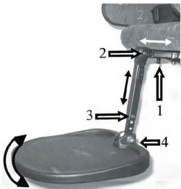
BENSTÖD - delade (fi g 12
Djup (i förhållande till sitsen): Lossa skruven (1). Drag ut benstödet så att dess led (2) motsvarar barnets knäled. Drag åt skruven.
Längd: Tag loss skruven (3) helt. Ställ in önskad benlängd. Drag åt skruven.
Vinkel (benstöd): Lossa skruven (2). Ställ in önskad vinkel på benstödet. Drag åt skruven.
Vinkel (fotplatta): Lossa skruven (4). Ställ in önskad vinkel. Drag åt skruven.
Verktyg: insexnyckel 5

natural_image
Mechanical assembly diagram showing a chair with labeled parts and directional arrows indicating movement (no text or symbols present)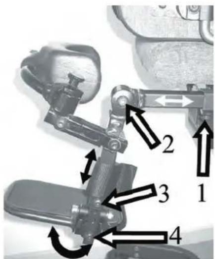
12
ARM REST - adjustments (fi g 10-11
Height: Loosen the screw (1) and set the desired height. Tighten the scre.
Width: Loosen the screw (2) and set the desired width. Tighten the screw
1 ool: insexnyckel 5 mm.
LEG RESTS – divided (fi g 12
Depth (in relation to the seat): Loosen the screw (1). Pull out the leg rest so that its joint (2) corresponds to the child's knee joint. Tighten the screw.
Length: Unscrew the screw (3) entirely. Set the desired leg length. Tighten the screw.
Angle (leg rest): Loosen the screw (2). Set the desired leg rest angle. Tighten the screw.
Angle (foot plate): Loosen the screw (4). Set the desired angle. Tighten the screw.
Tool: Allen key 5 mm
BENSTÖD - hel fotplatta (fi g 13
Djup: Lossa skruven (1). Justera till önskat djup. Drag åt skruven.
Längd: Tag bort skruven (3) helt. Ställ in önskad längd. Sätt tillbaka skruven och drag åt. Vinkel (benstöd): Lossa skruven (2). Ställ in önskad vinkel. Drag åt skruven.
Vinkel ( fotplatta): Skruva skruven (4) medurs för att minska vinkeln, moturs för att öka. Verktyg: insexnyckel 5 mm och 4 mm..
svenska english
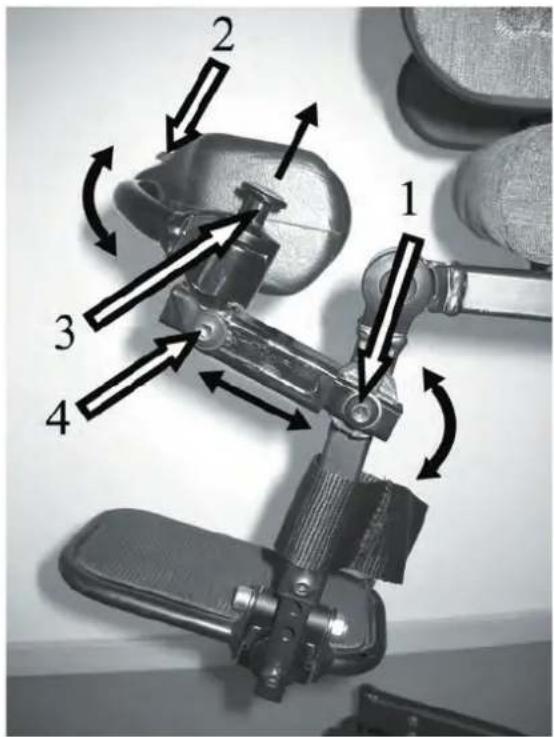
KNÄSTÖD - inställningar (fi g 14
Vinkel: Lossa skruven (1). Justera vinkel. Drag åt skruven.
Bredd och vinkel: Lossa skruven (2). Juster bredd resp. vinkel. Drag åt skruven.
Djup: Lossa skruven (4). Justera djupet. Drag åt skruven.
Fälla ut knästöd: Drag knoppen (3) rakt upp och vrid samtidigt knästödet åt sidan. Verktyg: insexnyckel 5 mm.
LEG RESTS – single foot plate (fig 13)
Depth: Loosen the screw (1). Adjust to the desired depth. Tighten the screw.
Length: Remove the screw (3) entirely. Set the desired length. Replace the screw and tighten.
Angle (leg rest): Loosen the screw (2). Set the desired angle. Tighten the screw.
Angle (foot plate): Turn the scre (4) clockwise to decrease the angle, counter clockwise to increase.
I ool: Allen key 5 mm and 4 mm.
KNEE SUPPORT - adjustments (fi g14
Angle: Loosen the screw (1). Adjust angle. Tighten the screw.
Width and angle: Loosen the screw (2). Adjust width and angle. Tighten the screw.
Depth: Loosen the screw (4). Adjust the depth. Tighten the screw.
Fold out knee rest: Pull the knob (3) straight up and turn the knee rest at the same time to the side.
Tool: Allen key 5 mm
13
14
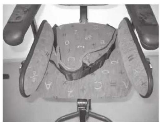
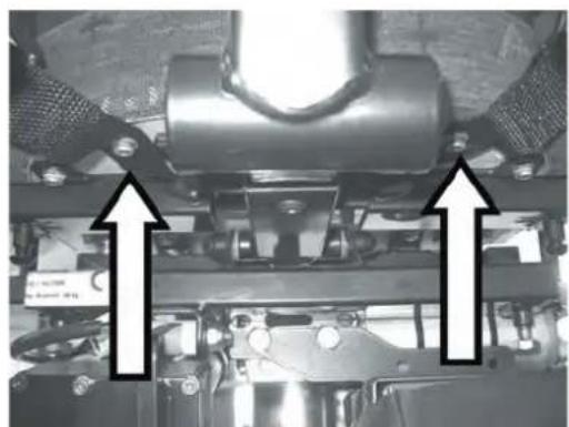
SITSBÄLTE (fi g 15-16
På undersidan av sitsen fi nns två skruvhål för infästning av sitsbälte. Använd två st M6 skruvar för att fästa bältets två delar i var sitt hål, se nedre bild.
SEAT BELT (fig 15-16)
There are two screw holes on the underside of the seat for affi xing a seat belt. Use two M6 screws to fasten the two parts of the belt in its respective hole, see lower picture.
svenska english
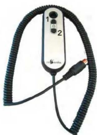
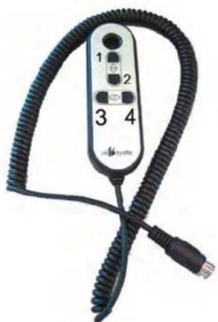
SITTHÖJD - ELEKTRISK (fig 17-18)
Med enbart sitslyft:
Höjning av sitthöjden: Tryck på knapp (1), (fi 17). Släpp knappen när önskad sitthöjd upp-nätts.
Sänkning av sitthöjden: Tryck på knapp (2), (fi g 17). Släpp knappen när önskad sitthöjd uppnätts.
Med sitslyft och sitsvinkling: Höjning och sänkning: Knapp (1), (fi g 18). föres framåt resp bakåt för sitshöjning resp. sitssänkning.
SEAT HEIGHT - ELECTRIC (fi g 17-18
With seat lift only:
Increasing seat height: Push the button (1), (fi g 17). Release the button when the desired seat height is reached.
Decreasing seat height: Push the button (2), (fi g 17). Release the button when the desired seat height is reached.
With seat lift and seat angling: Raising and lowering: Button (1), (fi g 18), is moved forward and backward respectively to raise and lower the seat.
natural_image
Close-up of an office chair seat with patterned cushion and visible letter markings (no readable text or symbols)15
natural_image
Mechanical assembly diagram showing two upward-pointing arrows indicating motion or force directions (no text or symbols present)16
natural_image
Close-up of a black flexible electronic device with two labeled buttons and a USB cable (no visible text or symbols)17
natural_image
Close-up of a black coiled cable with four labeled buttons (1-4), no visible text or symbols on the device itself.18
10
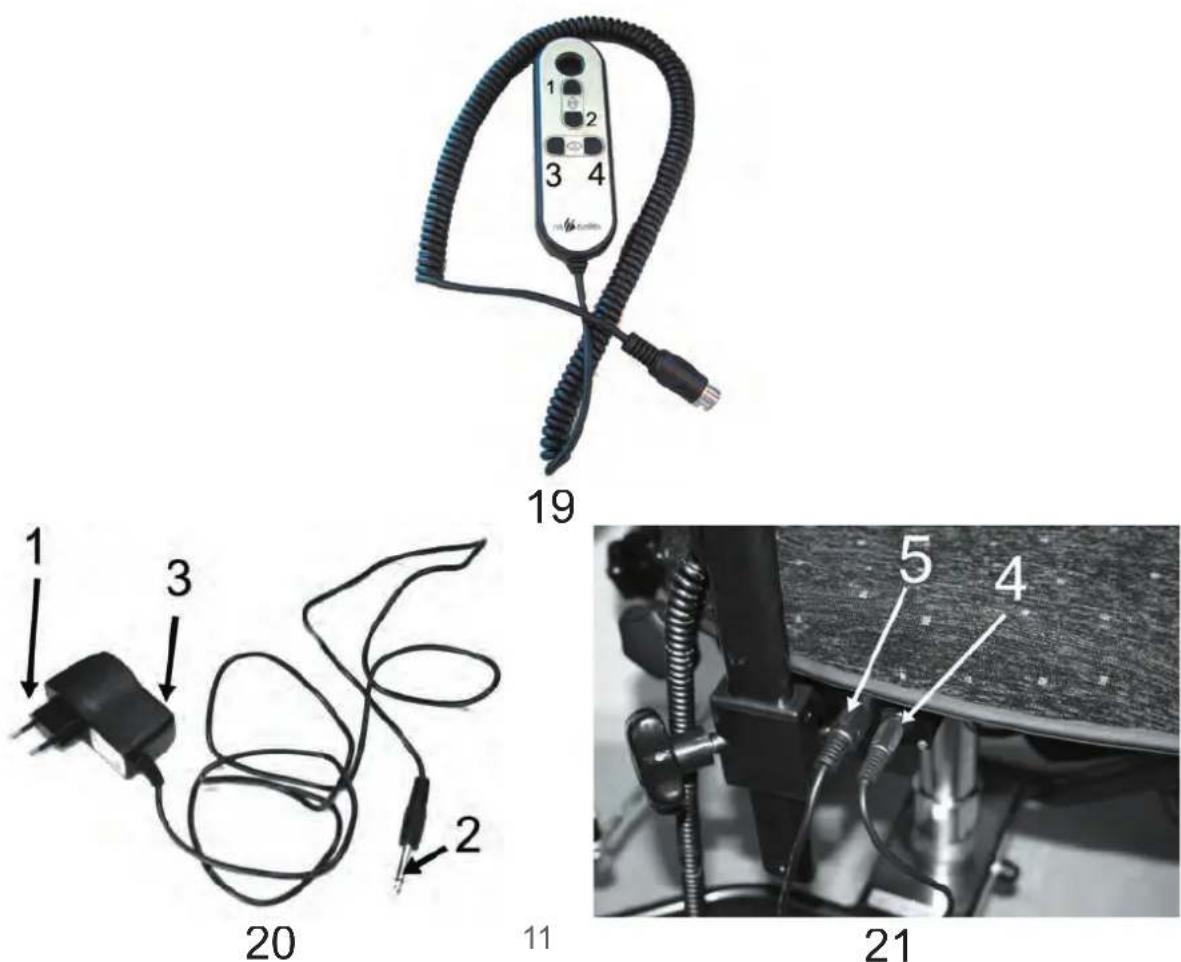
SITSVINKEL - ELEKTRISK (fi g 19
Vinkling framåt: För knapp (2) framåt tills önskad vinkel uppnätts. Släpp knappen.
Vinkling bakåt: För knapp (2) bakåt tills önskad vinkel uppnätts. Släpp knappen.
SEAT ANGLE - ELECTRIC (fi g 19
Angling forward: Move the button (2) forward until the desired angle is reached. Release the button.
Angling backward: Move the button (2) backward until the desired angle is reached. Release the button.
svenska english
LADDNING AV BATTER fig 20-21
- Anslut laddkontakten (2) till uttaget (4) på stolen. Diod (3) lyser grönt
- Anslut laddarens väggkontakt (1) till 220V Diod (3) lyser rött.
- När laddningen är klar lyser diod (3) grönt,
- Tag ur närkontakten (1) först och sen laddkontakt (2) ur uttag (4)
CHARGING THE BATTERY (fi g 20-21
- Connect the charger plug (2) to the socket (4) on the chair. LED (3) lights green.
- Connect the charger (1) to the wall socket. The LED lights red.
- When charging is completet the LED (3) lights green.
- Pull the charger(1) from the wall socket fi rs and then the charger plug (2) from socket (4).
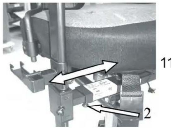
SKÖTSEL (fi g 22-23
Lyftställdon: Gas- och el-höjningens pelare (innerrör) kan börja kärva och gå ryckigt. Höj sitsen till sitt högsta läge och torka av pelaren ordentligt med en trasa. Smörj därefter in den med ett tefl onbaserat fetl
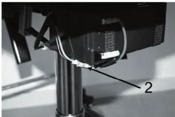
Säkring: Sitter vid batteriet bakom skydds höljet.se nedre bild. Säkringen är på 15A. Om stolen stannar plötsligt kan det bero på att säkringen löst ut. Byt ut säkringen mot en ny.
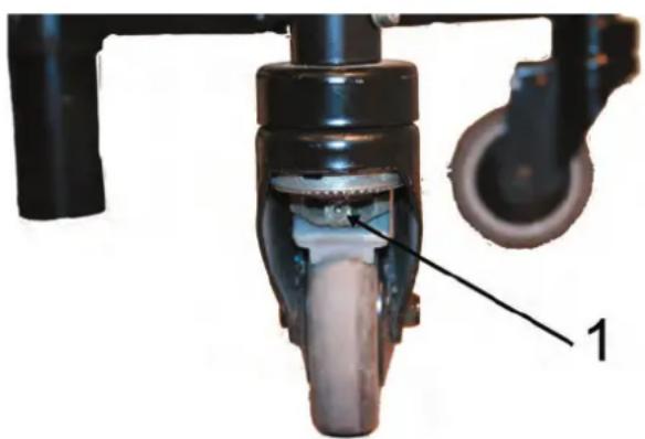
Hjul: De bakre läsbara hjulens polyuretanbanor slits med tiden och för att uppnå full bromsverkan behöver bromsen justeras. Justera bromsklacken med insexnyckel 3mm tills riktig bromsverkan uppnås. se övre bild.
Batteri: Batteriet på elstolen är underhållsfritt. Det ända man bhöver tänka på är att regelbundet ladda batteriet.
Kädsel: Tyget är gjort av Trevira och tål atl spillas på. Det klarar höga temperaturer (40° maskintvätt - överdrag).
Tag bort eventuella fl äckar med varmt tvålvat ten och en fuktig trasa.
OBS! Kontrollera att alla låsrattar och skruvar är ordentligt ätdragna efter att justeringar av stolen ar gjorda.
MAINTENANCE (fi g 22-23
Lift actuator: The gas and electrical lift column (interior tube) can stick and move jerkily. Raise the seat to its highest position and dry off the column properly with a cloth. Then lubricate it with Tefl on-based grease
Fuse: Located next to the battery behind the protective housing see lower picture. The fuse is 15A. If the chair stops suddenly, this can be due to the fuse having blown. Replace the fuse with a new one.
Wheels: The polyurethane rear lockable wheels' tracks become worn with time and to achieve full brake function the brake needs to be adjusted. Adjust the brake shoulder with a 3mm Allen key so that proper brake function is achieved. see upper picture.
Battery: The electrical chair's battery is maintenance-free. The only thing you have to keep in mind is to charge the battery periodically.
Upholstery: The upholstery is made of Trevira and withstands spilling. It withstands high temperatures (40° machine washing – cover).
Remove any spots with warm soapy water and a damp cloth.
NOTE! Ensure that all locking wheels and screws are well tightened when adjustments to the chair have been made.
natural_image
Close-up of a mechanical device with labeled parts, showing internal components and a numbered annotation (1) — no readable text or symbols beyond the label.22
natural_image
Close-up of a mechanical component with wires and a numbered label (2), no readable text or symbols present.23
SERVICE
Om stolen används mycket d.v.s. varje dag bör den lämnas in på service för översyn en gång per år. Detta för att kontrollera att funktionen och säkerheten på rullstolen bibehålls under hela dess livslangd. Vid behov av service kontaktas i första hand den lokala Hjälpmedelscentralen.
svenska english
GARANTI
Vi lämnar 2 års garanti på våra produkter för tillverkningsfel/skada. Undantag för klädsel, hjul och batterier där vi lämnar 1 års garanti. Normalt slitage ligger inte till grund för godkänd garanti. Vi rekommenderar våra kunder att använda produkten i enlighet med bruksanvisningen.
svenska english
CE - märkning
Denna produkt är CE – märkt enligt direktiv 93/42/EEC. CE märket fi nns på etiketten.
SERVICE
If the chair is used frequently, i.e. every day, it ought to have service once a year. This to control that the function and security of the wheel chair is kept through all its lifetime.
If service is needed contact primarily your local dealer.
WARRANTY
We give a 2 year warranty on our products for fabrication fault / damage. Exceptions are fabric, wheels and batteries where we give 1 year warranty. A normal wear and tear is not accepted as a warranty. We urge our customers to use the products according to the manual
CE - label
This product has the CE – mark according to the directive 93/42/EEC. The CE mark is on the label.


TEKNISKA FAKTA TECHNICAL DATA
fakta / data
| ISO 180903 ISO | ||
| Sits, storlekar 32x36, 36x40, 40x40 cm Seat, sizes | ||
| Rygg, storlekar 28x20, 28x33, 32x20, | Back, sizes | |
| 32x35, 32x40 cm | ||
| Sittdjup, ställbart (sits 36x40cm) 17-46cm | Seat depth, adjustable (seat 36x40cm) | |
| Sitthöjd, gaskolv 40-54 cm * Seat height, gas | ||
| Sitthöjd, elställdon kort 40-56 cm * Seat height, electric short | ||
| Sitthöjd, elställdon lång | 45-65 cm *(extra lång 49-74 | Seat height, electric long |
| Rygg, höjd ställbar | 37-54 cm Back, height adjustable | |
| Armstöd, storlek | 30x6 cm | Arm support, size |
| Armstöd, höjd ställbar | 0- 26 cm, | Arm support, height adjustable |
| Sits, tilt manuell -18° - +18° | Seat, tilt, manual | |
| Chassi, längd (flexbase) | 55 cm | Chassis, length (flexbase) |
| Chassi, bredd (flexbase) | 51 cm | Chassis, width (flexbase) |
| Tyg, färger | green ABC, blue ABC, black Dot | Fabric, colors |
| Vikt, totalt | 31 kg | Total weight |
| Brukarvikt, max | 50 kg | Max user weight |
| Batteri - elstol | 12V/7A Battery - electric | |
| * Sitslyftens position i chassit är ställbart i ett bultförband. Detta påverkar högsta och lägsta sitthöjd. | * the seatlifts position in the chassis is adjustable by loosen a screw joint.This affects the highest and lowest seatheight. | |
Eurovema
Creates mobility and ergonomics