
CS-RU12AKD - 8 PANASONIC - Panduan pengguna gratis
Temukan panduan perangkat secara gratis CS-RU12AKD PANASONIC dalam format PDF.


Pertanyaan pengguna tentang CS-RU12AKD PANASONIC
0 pertanyaan tentang perangkat ini. Jawab yang Anda tahu atau ajukan milik Anda sendiri.
Ajukan pertanyaan baru tentang perangkat ini
Unduh instruksi untuk 8 dalam format PDF gratis! Temukan panduan Anda CS-RU12AKD - PANASONIC dan ambil kembali perangkat elektronik Anda. Di halaman ini diterbitkan semua dokumen yang diperlukan untuk penggunaan perangkat Anda. CS-RU12AKD merek PANASONIC.
PANDUAN PENGGUNA CS-RU12AKD PANASONIC
Panasonic®
Operating & Installation Instructions
Air Conditioner
natural_image
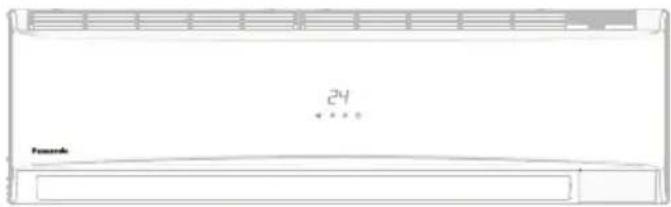
Line drawing of a front-end air conditioner unit with ventilation grille and temperature reading (no text or symbols beyond basic labels)Model No.
Indoor Unit
CS-RU9AKD Series
CS-RU12AKD Series
CS-RU18AKD Series
Outdoor Unit
CU-RU9AKD Series
CU-RU12AKD Series
CU-RU18AKD Series


Installation & Operating Instructions Air Conditioner
Thank you for purchasing Panasonic Air Conditioner. Installation instructions attached.
Before operating the unit, please read these operating instructions thoroughly and keep them for future reference.
Product warranty card including terms & conditions attached.
| WARNING | This symbol shows that this equipment uses a flammable refrigerant. If the refrigerant is leaked, together with an external ignition source, there is a possibility of ignition. | This symbol shows that the Operation Instructions should be read carefully. | |
| This symbol shows that a service personnel should be handling this equipment with reference to the Installation Instructions. | This symbol shows that there is information included in the Operation Instructions and/or Installation Instructions. |
ACI2PR61601-R0
Quick guide
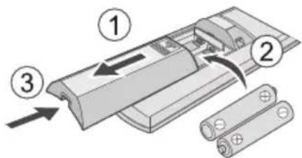


Inserting the batteries
① Pull out the back cover of remote control
② Insert AAA or R03 batteries
③ Close the cover
- Replace the batteries when remote display blinks "Lb" or remote gets off frequently.
Basic operation
① Select the desired mode

② Start/stop the operation

- Please note that the OFF indication is as follows:
To start:
To stop:

③ Select the desired temperature
- Selection range: 16 °C \~ 30 °C.
- Operating the unit at 24^ or higher degrees may save energy.
- Better comfort condition at 24°C or higher degrees.
- Use remote control within 7m from the remote control receiver of the indoor unit.
The illustrations in this manual are for explanation purposes only and may differ from the actual unit. They are subject to change without notice for future improvement.
Table of Contents
Safety precautions 4-9
How to use 10-11
To learn more 12
Cleaning instructions 13
Troubleshooting 14
Notes 15
Installation Instructions
Indoor Unit 16-19
Outdoor Unit 20-23
Safety precautions while installation ..... 24-26
Information ...... Back Cover Page
Accessories
- Remote control
• AAA or R03 batteries × 2 - Remote control holder
- Screws for remote control holder × 2
- PM 0.1 Filter.
Note:
- Unit Display and Remote showing HC, FC, 90, 80, 70, 55 and 40 are step of converti7 function and not Error codes.
- During Converti7, respective step value will be shown in place of set temp.
- In Case of any confusion or to Exit converti7 feature, press converti7 button repeatedly or ON / OFF button from remote.
- For more information on converti7 feature, please refer page no. 12.
Safety precautions
To prevent personal injury, injury to others or property damage, please comply with the following: Incorrect operation due to failure to follow instructions below may cause harm or damage, the seriousness of which is classified as below:

This appliance is filled with R32 (mild flammable refrigerant). If the refrigerant is leaked and exposed to an external ignition source, there is a risk of fire.

WARNING
This sign warns of death or serious injury.
CAUTION
This sign warns of injury or damage to property.
The instructions to be followed are classified by the following symbols:

This symbol denotes an action that is PROHIBITED.


These symbols denote actions COMPULSORY.


flowchart
graph TD
    A["Indoor unit"] --> B["Air outlet"]
    C["Outdoor unit"] --> D["Air outlet"]
    E["Remote control"] --> B
    F["Air inlet"] --> B
    G["Power supply"] --> B
    B --> H["Air inlet"]

WARNING
Indoor unit and outdoor unit

This appliance is not intended for use by persons (including children) with reduced physical, sensory or mental capabilities, or lack of experience and knowledge, unless they have been given supervision or instruction concerning use of the appliance by a person responsible for their safety. Children should be supervised to ensure that they do not play with the appliance.
The appliance shall be installed, and/or operated in a room and keep away from ignition sources, such as heat/sparks/open flame or hazardous areas such as gas appliances, gas cooking, reticulated gas supply systems or electric cooking, appliances, etc.
Be aware that refrigerant may not contain an odour, highly recommended to ensure suitable flammable refrigerant gas detectors are present, operating and able to warn of a leak.
Please consult authorised dealer or specialist to clean the internal parts, repair, install, remove and reinstall the unit. Improper installation and handling will cause leakage, electric shock or fire.
Confirm with authorised dealer or specialist on usage of any specified refrigerant type. Using refrigerant type other than the specified may cause product damage, burst and injury etc.

Do not use means to accelerate the defrosting process or to clean, other than those recommended by manufacturer. Any unfit method or using incompatible material may cause product damage, burst and serious injury.
Do not pierce or burn as the appliance is pressurized. Do not expose the appliance to heat, flame, sparks, or other sources of ignition. Else it may explode and cause injury or death.
Do not install the unit in a potentially explosive or flammable atmosphere. Failure to do so could result in fire.
Do not insert your fingers or other objects into the air conditioner indoor or outdoor unit, rotating parts may cause injury.

Do not touch the outdoor unit during lightning, it may cause electric shock.
Do not expose yourself directly to cold air for a long period to avoid excess cooling.
Do not sit or step on the unit, you may fall down accidentally.

Remote control

Do not allow infants and small children to play with the remote control to prevent them from accidentally swallowing the batteries.
Power supply

Do not use a modified cord, joint cord, extension cord or unspecified cord to prevent overheating and fire.


To prevent overheating, fire or electric shock:
- Do not share the same power outlet with other equipment.
- Do not operate with wet hands.
- Do not over bend the power supply cord.
- Do not operate or stop the unit by inserting or pulling out the power plug.

If the supply cord is damaged, it must be replaced by the manufacturer, service agent or similarly qualified persons in order to avoid a hazard.
It is strongly recommended to be installed with Earth Leakage Circuit Breaker (ELCB) or Residual Current Device (RCD) to prevent electric shock or fire.
To prevent overheating, fire or electric shock:
- Insert the power plug properly.
- Dust on the power plug should be periodically wiped with a dry cloth.
Stop using the product if any abnormality/failure occurs and disconnect the power plug or turn off the power switch and breaker. (Risk of smoke/fire/electric shock) Examples of abnormality/failure
• The ELCB trips frequently.
- Burning smell is observed.
- Abnormal noise or vibration of the unit is observed.
• Water leaks from the indoor unit.
• Power cord or plug becomes abnormally hot.
• Fan speed cannot be controlled.
- The unit stops running immediately even if it is switched on for operation.
- The fan does not stop even if the operation is stopped.
Contact your local dealer immediately for maintenance/repair.

This equipment must be earthed to prevent electrical shock or fire.

Prevent electric shock by switching off the power supply and unplug:
-Before cleaning or servicing,
-When extended non-use, or
-During abnormally strong lightning activity.
Precaution for using R32 refrigerant
The basic installation work procedures are the same as conventional refrigerant (R410A, R22) models.

Since the working pressure is higher than that of refrigerant R22 models, some of the piping and installation and service tools are special.
Especially, when replacing a refrigerant R22 model with a new refrigerant R32 model, always replace the conventional piping and flare nuts with the R32 and R410A piping and flare nuts on the outdoor unit side.
For R32 and R410A, the same flare nut on the outdoor unit side and pipe can be used.
Models that use refrigerant R32 and R410A have a different charging port thread diameter to prevent erroneous charging with refrigerant R22 and for safety.
Therefore, check beforehand. [The charging port thread diameter for R32 and R410A is 1/2 inch.] Be more careful than R22 so that foreign matter (oil, water, etc.) does not enter the piping.
Also, when storing the piping, securely seal the opening by pinching, taping, etc. (Handling of R32 is similar to R410A.)

CAUTION
Indoor unit and outdoor unit

Do not wash the indoor unit with water, benzine, thinner or scouring powder to avoid damage or corrosion at the unit.
Do not use for preservation of precise equipment, food, animals, plants, artwork or other objects. This may cause quality deterioration, etc.
Do not use any combustible equipment in front of the airflow outlet to avoid fire propagation.
Do not expose plants or pet directly to airflow to avoid injury, etc.
Do not touch the sharp aluminium fin, sharp parts may cause injury.

Do not switch ON the indoor unit when waxing the floor. After waxing, aerate the room properly before operating the unit.
Do not install the unit in oily and smoky areas to prevent damage to the unit.
Do not dismantle the unit for cleaning purpose to avoid injury.
Do not step onto an unstable bench when cleaning the unit to avoid injury.
Do not place a vase or water container on the unit. Water may enter the unit and degrade the insulation. This may cause an electric shock.
Do not open window or door for long time during operation, it may lead to inefficient power usage and uncomfortable temperature changes.
Safety precautions

Prevent water leakage by ensuring drainage pipe is:
-Connected properly,
-Kept clear of gutters and containers, or
-Not immersed in water
After a long period of use or use with any combustible equipment, aerate the room regularly.
After a long period of use, make sure the installation rack does not deteriorate to prevent the unit from falling down.
Remote control

Do not use rechargeable (Ni-Cd) batteries. It may damage the remote control.

To prevent malfunction or damage of the remote control:
- Remove the batteries if the unit is not going to be used for a long period of time.
- New batteries of the same type must be inserted following the polarity stated.
Power supply

Do not disconnect the plug by pulling the cord to prevent electric shock.
Precaution for using R32 refrigerant
The basic installation work procedures are the same as conventional refrigerant (R410A, R22) models.

1. Installation (Space)
- Must ensure the installation of pipe-work shall be kept to a minimum. Avoid use dented pipe and do not allow acute bending.
- Must ensure that pipe-work shall be protected from physical damage.
- Must comply with national gas regulations, state municipal rules and legislation. Notify relevant authorities in accordance with all applicable regulations.
- Must ensure mechanical connections be accessible for maintenance purposes.
- In cases that require mechanical ventilation, ventilation openings shall be kept clear of obstruction.
- When disposal of the product, do follow to the precautions in #12 and comply with national regulations.
Always contact to local municipal offices for proper handling.

2. Servicing
2-1. Service personnel
- Any qualified person who is involved with working on or breaking into a refrigerant circuit should hold a current valid certificate from an industry-accredited assessment authority, which authorizes their competence to handle refrigerants safely in accordance with an industry recognised assessment specification.
- Servicing shall only be performed as recommended by the equipment manufacturer. Maintenance and repair requiring the assistance of other skilled personnel shall be carried out under the supervision of the person competent in the use of flammable refrigerants.
• Servicing shall be performed only as recommended by the manufacturer.

2-2. Work
- Prior to beginning work on systems containing flammable refrigerants, safety checks are necessary to ensure that the risk of ignition is minimised.
For repair to the refrigerating system, the precautions in #2-2 to #2-8 must be followed before conducting work on the system.
• Work shall be undertaken under a controlled procedure so as to minimize the risk of a flammable gas or vapour being present while the work is being performed.
- All maintenance staff and others working in the local area shall be instructed and supervised on the nature of work being carried out.
- Avoid working in confined spaces.
- Wear appropriate protective equipment, including respiratory protection, as conditions warrant.
- Ensure that the conditions within the area have been made safe by limit of use of any flammable material. Keep all sources of ignition and hot metal surfaces away.

2-3. Checking for presence of refrigerant
• The area shall be checked with an appropriate refrigerant detector prior to and during work, to ensure the technician is aware of potentially flammable atmospheres.
- Ensure that the leak detection equipment being used is suitable for use with flammable refrigerants, i.e. non sparking, adequately sealed or intrinsically safe.
• In case of leakage/spillage happened, immediately ventilate area and stay upwind and away from spill/release.
- In case of leakage/spillage happened, do notify persons down wind of the leaking/spill, isolate immediate hazard area and keep unauthorized personnel out.

2-4. Presence of fire extinguisher
- If any hot work is to be conducted on the refrigeration equipment or any associated parts, appropriate fire extinguishing equipment shall be available at hand.
- Have a dry powder or CO^2 fire extinguisher adjacent to the charging area.

2-5. No ignition sources
- No person carrying out work in relation to a refrigeration system which involves exposing any pipe work that contains or has contained flammable refrigerant shall use any sources of ignition in such a manner that it may lead to the risk of fire or explosion. He/She must not be smoking when carrying out such work.
- All possible ignition sources, including cigarette smoking, should be kept sufficiently far away from the site of installation, repairing, removing and disposal, during which flammable refrigerant can possibly be released to the surrounding space.
- Prior to work taking place, the area around the equipment is to be surveyed to make sure that there are no flammable hazards or ignition risks.
- "No Smoking" signs shall be displayed.

2-6. Ventilated area
- Ensure that the area is in the open or that it is adequately ventilated before breaking into the system or conducting any hot work.
- A degree of ventilation shall continue during the period that the work is carried out.
- The ventilation should safely disperse any released refrigerant and preferably expel it externally into the atmosphere.

2-7. Checks to the refrigeration equipment
- Where electrical components are being changed, they shall be fit for the purpose and to the correct specification.
- At all times the manufacturer's maintenance and service guidelines shall be followed.
- If in doubt consult the manufacturer's technical department for assistance.
-
The following checks shall be applied to installations using flammable refrigerants.
-
The charge size is in accordance with the room size within which the refrigerant containing parts are installed.
- The ventilation machinery and outlets are operating adequately and are not obstructed.
- If an indirect refrigerating circuit is being used, the secondary circuit shall be checked for the presence of refrigerant.
- Marking to the equipment continues to be visible and legible. Markings and signs that are illegible shall be corrected.
- Refrigeration pipe or components are installed in a position where they are unlikely to be exposed to any substance which may corrode refrigerant containing components, unless the components are constructed of materials which are inherently resistant to being corroded or are properly protected against being so corroded.

2-8. Checks to electrical devices
- Repair and maintenance to electrical components shall include initial safety checks and component inspection procedures.
-
Initial safety checks shall include but not limit to:-
-
That capacitors are discharged: this shall be done in a safe manner to avoid possibility of sparking.
- That there no live electrical components and wiring are exposed while charging, recovering or purging the system.
-
That there is continuity of earth bonding.
-
At all times the manufacturer's maintenance and service guidelines shall be followed.
- If in doubt consult the manufacturer's technical department for assistance.
- If a fault exists that could compromise safety, then no electrical supply shall be connected to the circuit until it is satisfactorily dealt with.
- If the fault cannot be corrected immediately but it is necessary to continue operation, an adequate temporary solution shall be used.
• The owner of the equipment must be informed or reported so all parties are advised thereinafter.

3. Repairs to sealed components
- During repairs to sealed components, all electrical supplies shall be disconnected from the equipment being worked upon prior to any removal of sealed covers, etc.
- If it is absolutely necessary to have an electrical supply to equipment during servicing, then a permanently operating form of leak detection shall be located at the most critical point to warn of a potentially hazardous situation.
• Particular attention shall be paid to the following to ensure that by working on electrical components, the casing is not altered in such a way that the level of protection is affected.
This shall include damage to cables, excessive number of connections, terminals not made to original specifi cation, damage to seals, incorrect fi tting of glands, etc.
- Ensure that apparatus is mounted securely.
- Ensure that seals or sealing materials have not degraded such that they no longer serve the purpose of preventing the ingress of fl ammable atmospheres.
- Replacement parts shall be in accordance with the manufacturer's specifications.
NOTE: The use of silicon sealant may inhibit the effectiveness of some types of leak detection equipment.
Intrinsically safe components do not have to be isolated prior to working on them.
Safety precautions

4. Repair to intrinsically safe components
- Do not apply any permanent inductive or capacitance loads to the circuit without ensuring that this will not exceed the permissible voltage and current permitted for the equipment in use.
- Intrinsically safe components are the only types that can be worked on while live in the presence of a flammable atmosphere.
- The test apparatus shall be at the correct rating.
- Replace components only with parts specified by the manufacturer. Unspecified parts by manufacturer may result ignition of refrigerant in the atmosphere from a leak.

5. Cabling
- Check that cabling will not be subject to wear, corrosion, excessive pressure, vibration, sharp edges or any other adverse environmental effects.
- The check shall also take into account the effects of aging or continual vibration from sources such as compressors or fans.

6. Detection of flammable refrigerants
• Under no circumstances shall potential sources of ignition be used in the searching or detection of refrigerant leaks.
- A halide torch (or any other detector using a naked flame) shall not be used.

7. Leak detection methods
- Electronic leak detectors shall be used to detect flammable refrigerants, but the sensitivity may not be adequate, or may need re-calibration. (Detection equipment shall be calibrated in a refrigerant-free area.)
- Ensure that the detector is not a potential source of ignition and is suitable for the refrigerant used.
- Leak detection equipment shall be set at a percentage of the LFL of the refrigerant and shall be calibrated to the refrigerant employed and the appropriate percentage of gas (25 % maximum) is confirmed.
- Leak detection fluids are suitable for use with most refrigerants but the use of detergents containing chlorine shall be avoided as the chlorine may react with the refrigerant and corrode the copper pipe-work.
- If a leak is suspected, all naked flames shall be removed/extinguished.
- If a leakage of refrigerant is found which requires brazing, all of the refrigerant shall be recovered from the system, or isolated (by means of shut off valves) in a part of the system remote from the leak. Oxygen free nitrogen (OFN) shall then be purged through the system both before and during the brazing process.

8. Removal and evacuation
- When breaking into the refrigerant circuit to make repairs – or for any other purpose – conventional procedures shall be used.
However, it is important that best practice is followed since flammability is a consideration. The following procedure shall be adhered to: remove refrigerant -> purge the circuit with inert gas -> evacuate -> purge again with inert gas -> open the circuit by cutting or brazing - The refrigerant charge shall be recovered into the correct recovery cylinders.
- The system shall be "flushed" with OFN to render the unit safe.
• This process may need to be repeated several times. - Compressed air or oxygen shall not be used for this task.
- Flushing shall be achieved by breaking the vacuum in the system with OFN and continuing to fill until the working pressure is achieved, then venting to atmosphere, and finally pulling down to a vacuum.
- This process shall be repeated until no refrigerant is within the system.
- When the final OFN charge is used, the system shall be vented down to atmospheric pressure to enable work to take place.
• This operation is absolutely vital if brazing operations on the pipe work are to take place. - Ensure that the outlet for the vacuum pump is not close to any ignition sources and there is ventilation available.

9. Charging procedures
• In addition to conventional charging procedures, the following requirements shall be followed.
-Ensure that contamination of different refrigerants does not occur when using charging equipment.
-Hoses or lines shall be as short as possible to minimize the amount of refrigerant contained in them.
-Cylinders shall be kept upright.
-Ensure that the refrigeration system is earthed prior to charging the system with refrigerant.
-Label the system when charging is complete (if not already).
-Extreme care shall be taken not to over fill the refrigeration system.
- Prior to recharging the system it shall be pressure tested with OFN (refer to #7).
- The system shall be leak tested on completion of charging but prior to commissioning.
- A follow up leak test shall be carried out prior to leaving the site.
- Electrostatic charge may accumulate and create a hazardous condition when charging and discharging the refrigerant.
To avoid fire or explosion, dissipate static electricity during transfer by grounding and bonding containers and equipment before charging/discharging.

10. Decommissioning
- Before carrying out this procedure, it is essential that the technician is completely familiar with the equipment and all its details.
- It is recommended good practice that all refrigerants are recovered safely.
- Prior to the task being carried out, an oil and refrigerant sample shall be taken in case analysis is required prior to re-use of reclaimed refrigerant.
- It is essential that electrical power is available before the task is commenced.
a) Become familiar with the equipment and its operation.
b) Isolate system electrically.
c) Before attempting the procedure ensure that:
- mechanical handling equipment is available, if required, for handling refrigerant cylinders;
- all personal protective equipment is available and being used correctly;
- the recovery process is supervised at all times by a competent person;
- recovery equipment and cylinders conform to the appropriate standards.
d) Pump down refrigerant system, if possible.
e) If a vacuum is not possible, make a manifold so that refrigerant can be removed from various parts of the system.
f) Make sure that cylinder is situated on the scales before recovery takes place.
g) Start the recovery machine and operate in accordance with manufacturer's instructions.
h) Do not over fill cylinders. (No more than 80 % volume liquid charge).
i) Do not exceed the maximum working pressure of the cylinder, even temporarily.
j) When the cylinders have been filled correctly and the process completed, make sure that the cylinders and the equipment are removed from site promptly and all isolation valves on the equipment are closed off.
k) Recovered refrigerant shall not be charged into another refrigeration system unless it has been cleaned and checked.
- Electrostatic charge may accumulate and create a hazardous condition when charging or discharging the refrigerant.
To avoid fire or explosion, dissipate static electricity during transfer by grounding and bonding containers and equipment before charging/discharging.

11. Labelling
• Equipment shall be labelled stating that it has been de-commissioned and emptied of refrigerant.
• The label shall be dated and signed.
- Ensure that there are labels on the equipment stating the equipment contains flammable refrigerant.

12. Recovery
- When removing refrigerant from a system, either for servicing or decommissioning, it is recommended good practice that all refrigerants are removed safely.
- When transferring refrigerant into cylinders, ensure that only appropriate refrigerant recovery cylinders are employed.
- Ensure that the correct number of cylinders for holding the total system charge are available.
- All cylinders to be used are designated for the recovered refrigerant and labelled for that refrigerant (i.e. special cylinders for the recovery of refrigerant).
- Cylinders shall be complete with pressure relief valve and associated shut-off valves in good working order.
- Recovery cylinders are evacuated and, if possible, cooled before recovery occurs.
• The recovery equipment shall be in good working order with a set of instructions concerning the equipment that is at hand and shall be suitable for the recovery of flammable refrigerants.
• In addition, a set of calibrated weighing scales shall be available and in good working order. - Hoses shall be complete with leak-free disconnect couplings and in good condition.
- Before using the recovery machine, check that it is in satisfactory working order, has been properly maintained and that any associated electrical components are sealed to prevent ignition in the event of a refrigerant release.
Consult manufacturer if in doubt.
- The recovered refrigerant shall be returned to the refrigerant supplier in the correct recovery cylinder, and the relevant Waste Transfer Note arranged.
- Do not mix refrigerants in recovery units and especially not in cylinders.
- If compressors or compressor oils are to be removed, ensure that they have been evacuated to an acceptable level to make certain that flammable refrigerant does not remain within the lubricant.
• The evacuation process shall be carried out prior to returning the compressor to the suppliers. - Only electric heating to the compressor body shall be employed to accelerate this process.
- When oil is drained from a system, it shall be carried out safely.
How to use
MODE

To select operation mode
AUTO - For your convenience
- Unit run with optimised settings.
- You can change the temperature according to your comfort.
COOL - To enjoy cool air
• To reduce power consumption during COOL mode, use curtains to screen off sunlight and outdoor heat.
DRY - To dehumidify the environment
- Unit automatically operates at Low fan speed to give a gently cooling operation.
FAN - To operate Air-Con in "Fan Only" mode
- Only indoor unit fan operates as per remote settings.
• Outdoor is OFF, so no cooling achieved. - Provides air circulation in the room.
* Indoor unit temp. display will show set temp. for AUTO,COOL & DRY mode and room temp. for FAN mode.
SLEEP

To maximise comfort while sleeping
- This operation provides you with a comfortable environment while sleeping by gradually increase the set temperature 1 °C after every "3" hours operation.
• The unit is turned off after "8" hours automatically. - "SL" will be displayed on Remote.
- Can be cancelled by pressing the respective button again.

*FOR RU SERIES
Remote control receiver and indicator
Remote control display

Press & hold for "5" seconds to turn ON/OFF the hidden display.
Press to restore the remote control to default setting
Press for "5" seconds to lock / unlock remote keypad.
When keypad is locked, remote display will show 'Lo' when any button is pressed or press to set clock.
Not used in normal operations.
To adjust horizontal airflow direction
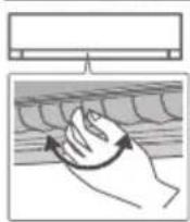
- Manually adjustable.
Auto OFF/ON button

Use when remote control is misplaced or a malfunction occurs. Raise the front panel:
- Press the button to turn on.
- Press the button again to turn off.
How to use (For COOLING Models)
To select fan speed
(Remote control display)

- For AUTO, the indoor fan speed is automatically adjusted according to the operation mode.

To adjust vertical airflow direction
(Remote control display)

- If AUTO is set, the louver swings up/down automatically.
- Do not adjust the louver by hand.

To clean dust on Evap. Coil of the Air-Conditioner Unit
- 'CL' will be displayed on unit and remote controller. ('CL' on unit display is not applicable for LU Models)
- While 'CL' is displayed, all other functions of the remote controller will be disabled, except for ON/OFF button. Applicable for 10 to 15 minutes.
• This feature can only be used in OFF condition.
POWERFUL

To reach temperature quickly

POWERFUL
- This operation is to achieve faster cooling for 1 hour in COOL mode only.
To Select ECO
- Press & hold POWERFUL button for "5" seconds.
- Default temperature is now 26°C.
- Can be used in COOL mode only, to save Energy.
Auto Restart Control
- If power is resumed after a power failure, the operation will restart automatically after a period of time with previous operation mode and airflow direction.
- SLEEP, TIMER etc. functions will not resume after power failure.
- In TIMER set conditions if there is power reset then unit will start in stand by mode.
To set the timer
To turn ON or OFF the unit at a preset time.

① Select ON or OFF timer
- Press the OFF button.
Example: OFF at 14:00


② Set the time
- Press OFF button again to increase timer time in step of "10" minutes.
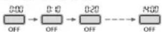
Confirm
- Wait for "3" seconds to set timer.



- To cancel ON or OFF timer, press CANCEL.
- If timer is cancelled manually or due to power failure, you can restore the timer again by pressing ON or OFF then wait for "3" seconds.
- The nearest timer setting will be displayed and will activate in sequence.
- When ON Timer is set, the unit may start earlier (up to "15" minutes) before the actual set time in order to achieve the desired temperature on time.
Operation conditions
Use this air conditioner under the following temperature range.
DBT : Dry bulb temperature
WBT : Wet bulb temperature
| Temperature(°C) | Indoor | Outdoor | |||
| DBT | WBT | DBT | WBT | ||
| COOL | Max. | 35 | 24 | 52 | 30 |
| Min. | 16 | 11 | 16 | 11 | |
To Learn more...
To select different Performance modes

This operation Changes Air Conditioner Performance in COOL Mode only.
- Step 1: "HE" is display on Unit and Remote. Unit will operate in High Capacity Mode.
- Step 2: "FC" is display on Unit and Remote. Unit Input Power will be upto 100% .
- Step 3: "90" is display on Unit and Remote. Unit Input Power will be upto 90%.
- Step 4: "B0" is display on Unit and Remote. Unit Input Power will be upto 80%.
- Step 5: "70" is display on Unit and Remote. Unit Input Power will be upto 70%.
- Step 6: "55" is display on Unit and Remote. Unit Input Power will be upto 55% .
-
Step 7: "40" is display on Unit and Remote. Unit Input Power will be upto 40%.
-
Press "converti7" button again to exit from this feature.
- Set temperature will display about 5 sec. if press fan speed button or change temperature.
- User can select Fan speed as per need.
- Capacity may decrease when "converti7" mode is Selected.
- Capacity measurement is done Under Standard Lab condition and may vary based on Ambient Temperature and Room Size.
- POWERFUL and SLEEP will not work in this mode and vice versa.
Cleaning instructions
To ensure optimal performance of the unit, cleaning has to be carried out at regular intervals. Please consult authorised dealer.
- Switch off the power supply and unplug before cleaning.
- Do not touch the aluminium fin, sharp parts may cause injury.
- Do not use benzine, thinner or scouring powder.
- Use only soap (≈ pH 7) or neutral household detergent.
- Do not use water hotter than 40^ .
Indoor unit
Wipe the unit gently with a soft, dry cloth.

Front panel
Wash gently and dry.
Remove the front panel
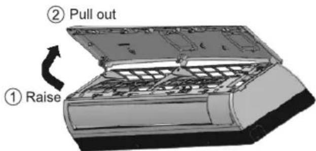
Close it securely
① Insert at both sides

natural_image
Illustration of an open air conditioner unit with a magnified inset showing internal components (no text or symbols)② Close down
③ Press both ends of the front panel
Indoor unit
Front Panel
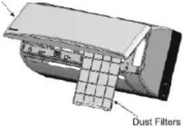
Dust filters
Every 2 weeks
- Wash/rinse the dust filters gently with water to avoid damage to the filter surface.
- Dry the dust filters thoroughly under shade, away from fire or direct sunlight.
- Replace any damaged filters.
- Please remove the PM 0.1 Filter before wash/rinse the dust filter with water.

Remove air filter

natural_image
Illustration of a hand holding a curved panel with a small inset showing a black arrow (no text or symbols)Attach air filter
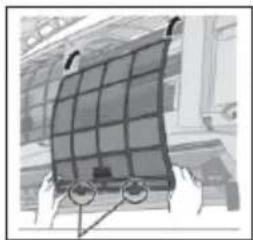
natural_image
Illustration of hands holding a grid-mounted solar panel (no text or symbols visible)Insert into the unit
PM 0.1 filter

- Clean the filter whenever necessary.
- Don't wash/rinse the filter with water.
- The surface of the filter shouldn't be rubbed with any object.
- The filter shouldn't be pulled with strong force as it may get damaged.
For seasonal inspection after extended non-use
- Checking of remote control batteries.
• No obstruction at air inlet and air outlet vents.
• After 15 minutes of operation, it is normal to have the following temperature difference between air inlet and air outlet vents:
$$ \mathrm{COOL}: \geq 8 ^ {\circ} \mathrm{C} $$
For extended non-use
- Turn off the power supply and unplug.
- Remove the remote control batteries.
Troubleshooting
The following symptoms do not indicate malfunction.
| Symptom | Cause |
| Mist emerges from indoor unit. | Condensation effect due to cooling process. |
| Water flowing sound during operation. | Refrigerant flow inside the unit. |
| The room has a peculiar odour. | This may be due to damp smell emitted by the wall, carpet, furniture or clothing. |
| Indoor fan stops occasionally during automatic fan speed setting. | This helps to remove the surrounding odour. |
| Operation is delayed a few minutes after restarting. | The delay is a protection to the unit's compressor. |
| Outdoor unit emits water/steam. | Condensation or evaporation occurs on pipes. |
| TIMER indicator is always on. | The timer setting repeats daily once set. |
| Cracking sound during operation. | Changes of temperature caused the expansion/contraction of the unit. |
| Discoloration of some plastic parts. | Discoloration is subject to material types used in plastic parts, accelerated when exposed to heat, sun light, UV light, or environmental factor. |
| Wi-Fi LED stays ON during unit turn OFF. | Unit's Wi-fi connection with the router is activated. |
| Wi-Fi LED continuously blinking. | Check unit's Wi-Fi connection with router. |
Check the following before calling for servicing.
| Symptom | Check |
| Operation in COOL mode is not working efficiently. | Set the temperature correctly.Close all doors and windows.Clean or replace the filters.Clear any obstruction at the air inlet and air outlet vents. |
| Noisy during operation. | Check if the unit has been installed at an incline.Close the front panel properly. |
| Remote control does not work.(Display is dim or transmission signal is weak.) | Insert the batteries correctly.Replace weak batteries. |
| The unit does not work. | Check if the circuit breaker is tripped.Check if timers have been set. |
| The unit does not receive the signal from the remote control. | Make sure the receiver is not obstructed.Certain fluorescent lights may interfere with signal transmitter. Please consult authorised dealer. |
NON SERVICEABLE CRITERIAS
TURN OFF POWER SUPPLY AND UNPLUG then please consult authorised dealer under the following conditions:
• Abnormal noise during operation.
• Water/foreign particles have entered the remote control.
• Water leaks from Indoor unit.
• Circuit breaker switches off frequently.
• Power cord becomes unnaturally warm.
- Switches or buttons are not functioning properly.
- The unit stops and some alpha-numeric codes appear on IDU display.
Notes
Troubleschooling
English
INDOOR UNIT

SELECT THE BEST LOCATION
(Refer to "Select the best location" section)
HOW TO FIX INSTALLATION PLATE
The mounting wall shall be strong and solid enough to prevent it from vibration.
(A).

| Model | Dimension | ||
| 1 | 2 | ||
| RU9***RU12***RU18*** |  | 50 mm | 82 mm |
The edge of indoor unit should be more than ① at right and left of the wall. The distance from installation plate edge to ceiling should more than ②.
- Mount the installation plate on the wall with 5 screws or more (at least 5 screws). (If mounting the unit on the concrete wall, consider using anchor bolts.)
- Always mount the installation plate horizontally by aligning the marking-off line with the thread and using a level gauge.
- Drill the piping plate hole with 70 mm hole-core drill.
- Putting measuring tape at position as shown in the diagram above. The hole center is obtained by measuring the distance namely 128 mm for left and right hole respectively. Another method is intersection point of arrow mark extension. The meeting point of the extension arrow mark is the hole center position.
- Drill the piping hole at either the right or the left and the hole should be slightly slanting to the outdoor side (refer to step 3)

TO DRILL A HOLE IN THE WALL AND INSTALL A SLEEVE OF PIPING
- Insert the piping sleeve to the hole.
- Fix the bushing to the sleeve.
- Cut the sleeve until it extrudes about 15 mm from the wall.

CAUTION

When the wall is hollow, please be sure to use the sleeve for tube assembly to prevent dangers caused by mice biting the connection cable.
- Finish by sealing the sleeve with putty or caulking compound at the final stage.


INDOOR UNIT INSTALLATION
- Do not turn over the unit without it's shock absorber during pull out the piping. It may cause intake grille damage.
- Use shock absorber during pull out the piping to protect the intake grille from damage.

1. FOR THE RIGHT REAR PIPING
Step-1
Pull out the Indoor piping

Step-2
Install the Indoor Unit

Step-3
Secure the Indoor Unit

Step-4
Insert the power supply cord and connection cable
- Insert the cables from bottom of the unit through the control board hole until terminal board area.
2. FOR THE RIGHT AND RIGHT BOTTOM PIPING
Step-1
Pull out the Indoor piping

Step-2
Install the Indoor Unit

Step-3
Insert the power supply cord and connection cable

- Insert the cables from bottom of the unit through the control board hole until terminal board area.
Step-4
Secure the Indoor Unit
Right Rear piping

How to keep the cover
In case of the cover is cut, keep the cover at the rear of chassis as shown in the illustration for future reinstallation.
(Left, right and 2 bottom covers for piping.)

Right and Right Bottom piping
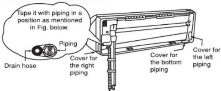
3. FOR THE EMBEDDED PIPING
Step-1 Replace the drain hose

Step-2 Bend the embedded piping

- Use a spring bender or equivalent to bend the piping so that the piping is not crushed.
Step-3 Pull the connection cable into Indoor Unit

- The power supply cord and indoor unit and outdoor unit connection cable can be connected without removing the front grille.
Step-4 Cut and flare the embedded piping

- When determining the dimensions of the piping, slide the unit all the way to the left on the installation plate.
- Refer to the section "Cutting and flaring the piping".
Step-5 Install the Indoor Unit

Step-6 Connect the piping

- Please refer to "Connecting the piping" column in outdoor unit section. (Below steps are done after connecting the outdoor piping and gas-leakage con rmation.)
Step-7 Insulate and nish the piping

- Please refer to "Insulation of piping connection" column as mentioned in indoor/outdoor unit installation.
Step-8 Secure the Indoor Unit
Install the indoor unit
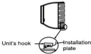
Hook the indoor unit onto the upper portion of installation plate. (Engage the indoor unit with the upper edge of the installation plate). Ensure the hooks are properly seated on the installation plate by moving it in left and right.
Secure the Indoor Unit
Press the lower left and right side of the unit against the installation plate until hooks engages with their slot (sound click).

Insert the connection cable

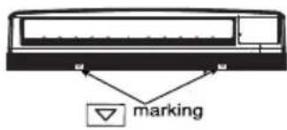
To take out the unit, push the ▼ marking at the bottom unit, and pull it slightly towards you to disengage the hooks from the unit.
(Drain pipe to be assemble on right rear drain position only)
HOW TO DETACH INSTALLATION PLATE
- Before installation insure to remove this screw to detach installation plate from Chassis.

natural_image
Technical line drawing of a car air conditioning unit (no text or symbols)- How to pull the piping and drain hose out, in case of the embedded piping.


5
CONNECT THE CABLE TO THE INDOOR UNIT
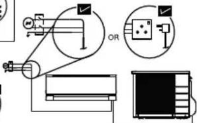
The power supply cord, indoor and outdoor unit connection cable can be connected without removing the front grille.
① Install the indoor unit on the installing holder that mounted on the wall.
② Open the front panel and grille door by loosening the screw.
③ Cable connection to the power supply through Isolating Devices (Disconnecting means).
- Connect the approved polychloroprene sheathed power supply cord 3 x 1.5 mm ^2 (1.5 \~ 2.0 HP) or 3 x 2.5 mm ^2 (2.5 \~ 3.0HP), type designation IS 694 or 60245 IEC 57 or heavier cord to the terminal board, and connect the other end of the cable to Isolating Devices (Disconnecting means).
- Do not use joint power supply cord. Replace the wire if the existing wire (from concealed wiring, or otherwise) is too short.
- In unavoidable case, joining of power supply cord between isolating devices and terminal board of air conditioner shall be done by using approved socket and plug rated 15/16A (1.5HP) or 16A (2.0HP) or 20A (2.5 \~ 3.0HP). Wiring work to both socket and plug must follow to national wiring standard.
④ Bind all the power supply cord lead wire with tape and route the power supply cord via the left escapement.
⑤ Connection cable between indoor unit and outdoor unit shall be approved polychloroprene sheathed 4 x 1.0 mm²(1.5 \~ 1.8HP), 4 x 1.5 mm²(2.0HP) or 4 x 2.5mm²(2.5 \~ 3.0HP) flexible cord, type designation IS 694 or 60245 IEC 57 or heavier cord.
⑥ Bind all the indoor and outdoor connection cable with tape and route the connection cable via the right escapement.
⑦ Remove the tapes and connect the power supply cord and connection cable between indoor unit and outdoor unit according to the diagram below.
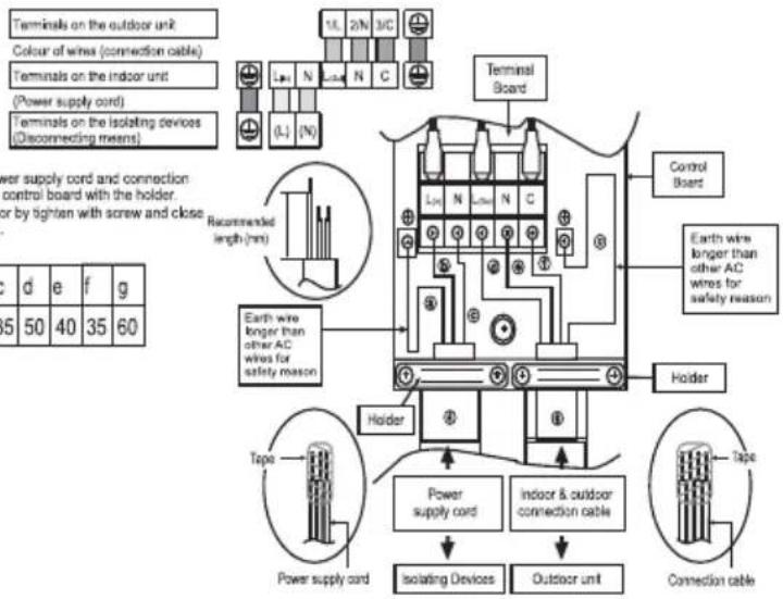
Note:
- Isolating Devices (Disconnecting means) should have minimum 3.0 mm contact gap.
- Ensure the colour of wires of outdoor unit and the terminal Nos. are the same to the indoor's respectively.
- Earth wire shall be Yellow/Green (Y/G) in colour.
WIRE STRIPPING, CONNECTING REQUIREMENT
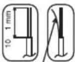
Wire stripping
No loose strand when inserted
Indoor/outdoor connection terminal board
5 mm or more (gap between wires)
Conductor fully inserted
Conductor over inserted

ACCEPT

PROHIBITED
Fork Terminal fully inserted

ACCEPT
Conductor not fully inserted

PROHIBITED

WARNING
RISK OF FIRE
JOINING OF WIRES MAY CAUSE OVERHEATING AND FIRE.


Do not joint wires

flowchart
graph TD
    A["Air Inlet"] --> B["Reactor Unit"]
    B --> C["Control Panel"]
    C --> D["Control Panel with OR"]
    D --> E["Output"]
    style A fill:#f9f,stroke:#333
    style B fill:#ccf,stroke:#333
    style C fill:#cfc,stroke:#333
    style D fill:#fcc,stroke:#333
Use complete wire without joining.
Use approved socket and plug with earth pin.
Wire connection in this area must follow to national wiring rules.
CUTTING AND FLARING THE PIPING
- Please cut using pipe cutter and then remove the burrs.
- Remove the burrs by using reamer. If burrs is not removed, gas leakage may be caused. Turn the piping end down to avoid the metal powder entering the pipe.
- Please make flare after inserting the flare nut onto the copper pipes.

- To cut
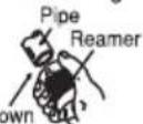
Point down
- To remove burrs

- To flare

Improper aring
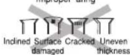
When properly flared, the internal surface of the flare will evenly shine and be of even thickness. Since the flare part comes into contact with the connections, carefully check the flare finish.
OUTDOOR UNIT
1
SELECT THE BEST LOCATION
(Refer to "Select the best location" section)
2
INSTALL THE OUTDOOR UNIT
• After selecting the best location, start installation to Indoor/Outdoor Unit Installation Diagram.
1. Fix the unit on concrete or rigid frame firmly and horizontally by bolt nut (ø10 mm).
2. When installing at roof, please consider strong wind and earthquake.
Please fasten the installation stand firmly with bolt, screws or nails.

| MODEL | A | B | C | D |
| RU9***, RU12*** | 484mm | 100.5mm | 11.5mm | 260mm |
| RU18*** | 513mm | 148mm | 4.5mm | 292mm |
3
CONNECT THE PIPING
Connecting The Piping to Indoor
For connection joint location at outside building :
Please make flare after inserting flare nut (locate at joint portion of tube assembly) onto the copper pipe. (In case of using long piping)
Connect the piping :
- Align the center of piping and sufficiently tighten the flare nut with fingers.
• Further tighten the flare nut with torque wrench in specified torque as stated in the table.

Connecting The Piping to Outdoor
- Decide piping length and then cut by using pipe cutter.
- Remove burrs from cut edge.
- Make flare after inserting the flare nut (locate at valve) onto the copper pipe. Align center of piping to valve and then tighten with torque wrench to the specified torque as stated in the table.
| Do not overtighten, overtightening may cause gas leakage. | |
| Piping size | Torque |
| 6.35 mm (1/4") | [18 N·m (1.8 kgf·m)] |
| 9.52 mm (3/8") | [42 N·m (4.3 kgf·m)] |
| 12.7 mm (1/2") | [55 N·m (5.6 kgf·m)] |
| 15.88 mm (5/8") | [65 N·m (6.6 kgf·m)] |
| 19.05 mm (3/4") | [100 N·m (10.2 kgf·m)] |
WHEN INSTALLING AN AIR CONDITIONER, BE SURE TO EVACUATE THE AIR INSIDE THE INDOOR UNIT AND PIPES in the following procedure.

Do not purge the air with refrigerants but use a vacuum pump to vacuum the installation.

There is no extra refrigerant in the outdoor unit for air purging.
- Connect a charging hose with a push pin to the Low side of a charging set and the service port of the 3-way valve.
- Be sure to connect the end of the charging hose with the push pin to the service port.
- Connect the center hose of the charging set to a vacuum pump.
- Turn on the power switch of the vacuum pump and make sure that the needle in the gauge moves from 0 cmHg (0 MPa) to -76 cmHg (-0.1 MPa). Then evacuate the air approximately ten minutes.
- Close the Low side valve of the charging set and turn off the vacuum pump. Make sure that the needle in the gauge does not move after approximately five minutes. Note : BE SURE TO TAKE THIS PROCEDURE IN ORDER TO AVOID REFRIGERANT GAS LEAKAGE.
- Disconnect the charging hose from the vacuum pump and from the service port of the 3-way valve.
- Tighten the service port caps of the 3-way valve at a torque of 18 N·m with a torque wrench.
- Remove the valve caps of both of the 2-way valve and 3-way valve. Position both of the valves to "OPEN" using a hexagonal wrench (4 mm).
- Mount valve caps onto the 2-way valve and the 3-way valve.
- Be sure to check for gas leakage.
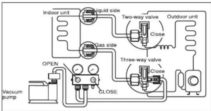
flowchart
graph TD
    A["Indoor unit"] --> B["Liquid side"]
    B --> C["Two-way valve"]
    C --> D["Close"]
    D --> E["Outdoor unit"]
    F["Vacuum pump"] --> G["OPEN"]
    G --> H["CLOSE"]
    H --> I["Three-way valve"]
    I --> J["Close"]
    J --> K["Three-way valve"]
    K --> L["Three-way valve"]
    L --> M["Three-way valve"]
    M --> N["Three-way valve"]
- If gauge needle does not move from 0 cmHg (0 MPa) to -76 cmHg (-0.1 MPa), in step ③ above take the following measure:
- If the leak stops when the piping connections are tightened further, continue working from step ③.
- If the leak does not stop when the connections are retightened, repair location of leak.
- Do not release refrigerant during piping work for installation and reinstallation.
- Take care of the liquid refrigerant, it may cause frostbite.
EVALUATION OF THE PERFORMANCE
- Operate the unit at cooling/heating operation mode for fifteen minutes or more.
• Measure the temperature of the intake and discharge air. - Ensure the difference between the intake temperature and the discharge is more than 8^ C during Cooling operation or more than 14^ C during Heating operation.

Pump Down Method When Reuse Existing Piping (R22 Model) for R32 Model
Compressor oil of R22 model is insoluble in compressor oil of R32 model. The mixing of compressor oil may cause damage of compressor.
Possibility of Mixing
■ Reuse of piping of R22 model is dangerous because of its compressor oil.
■ Reuse the piping of R22 model only when it is unavoidable, eg. concealed piping.
■ When reuse piping of R22 model, pump down must be carried out properly to ensure compressor oil which is remained inside piping is collected away.
To Reuse Old Piping
■ Piping of R22 model can be reused only when air-conditioner is properly pumped down.
■ The purpose of pump down is to collect back the compressor oil (which is mixed with refrigerant and circulating inside refrigeration cycle) properly into the outdoor unit of air conditioner.
Proper Pump Down Method
① Operate air conditioner at cooling mode for 10 \~ 15 minutes.
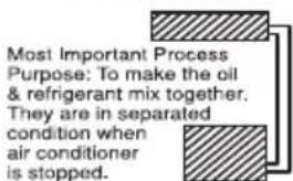
② After 10 \~ 15 minutes of pre operation, close 2 way valve. After 3 minutes, close 3 way valve.

③ Take out air conditioner unit.
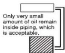
④ Install new refrigerant air conditioner

In case pump down cannot be done. Please flush the piping using R32 refrigerant. Must do re-flare of pipe before connecting to units.
CHECK ITEMS
Is there any gas leakage at flare nut connections?
☐ Has the heat insulation been carried out at flare nut connection?
Is the connection cable being fixed to terminal board firmly?
Is the connection cable being clamped firmly?
Is the drainage ok?
(Refer to "Check the drainage" section)
Is the earth wire connection properly done?
☐ Is the indoor unit properly hooked to the installation plate?
Is the power supply voltage complied with rated value?
□ Is there any abnormal sound?
Is the cooling/heating operation normal?
Is the thermostat operation normal?
Is the remote control's LCD operation normal?
Is the PM 0.1 Filter installed?
5
CONNECT THE CABLE TO THE OUTDOOR UNIT
- Remove the control board cover from the unit by loosening the screw.
- Connection cable between indoor unit and outdoor unit shall be approved polychloroprene sheathed 4 x 1.0 mm² (1.5 \~ 1.8HP), 4 x 1.5 mm² (2.0HP) or 4 x 2.5mm² (2.5 \~ 3.0HP) flexible cord, type designation IS 694 or 60245 IEC 57 or heavier cord. Do not use joint connection cable. Replace the wire if the existing wire (from concealed wiring, or otherwise) is too short.
| Terminals on the outdoor unit | 1/L | 2/N | 3/C |
| Colour of wires | |||
| Terminals on the indoor unit | L | N | C |
-
Secure the cable onto the control board with the holder.
-
Attach the control board cover back to the original position with screw.
-
For wire stripping and connection requirement, refer to instruction ⑤ of indoor unit.

WARNING

This equipment must be properly earthed.
- Earth wire shall be Yellow/Green (Y/G) in colour.
6
PIPING INSULATION
- Please carry out insulation at pipe connection portion as mentioned in Indoor/Outdoor Unit Installation Diagram. Please wrap the insulated piping end to prevent water from going inside the piping.
- If drain hose or connecting piping is in the room (where dew may form), please increase the insulation by using POLY-E FOAM with thickness 6 mm or above.
HOW TO TAKE OUT FRONT GRILLE
(Screw Front Grille with Chassis: 3 screw In case of RU9, RU12 & 4 screw In case of RU18)

Please follow the steps below to take out front grille if necessary such as when servicing.
-
Set the vertical air flow direction louvers to the horizontal position
-
Remove the 2 caps (1.5 \~ 2.0HP) or 3 caps (2.0 \~ 2.5HP) on the front grille as shown in the illustration at top, and then remove the 2 (1.5 \~ 2.0HP) or 4 (2.0 \~ 2.5HP) mounting screws.
-
Pull the lower section of the front grille towards you to remove the front grille.
-
Set the vertical air flow direction louvers to the horizontal position
- Remove the 2 caps (1.5 \~ 2.0HP) or 3 caps (2.0 \~ 2.5HP) on the front grille as shown in the illustration at top, and then remove the 2 (1.5 \~ 2.0HP) or 4 (2.0 \~ 2.5HP) mounting screws.
- Pull the lower section of the front grille towards you to remove the front grille.
When reinstalling the front grille, first set the vertical airflow direction louver to the horizontal position and then carry out above steps 2 -3 in the reverse order.
AUTO SWITCH OPERATION
The below operations will be performed by pressing the "AUTO" switch.
- AUTO OPERATION MODE
The Auto operation will be activated immediately once the Auto Switch is pressed.

natural_image
Technical line drawing of a mechanical assembly with a hand operating a tool (no text or symbols present)CHECK THE DRAINAGE
- Open front panel and remove air filters.
(Drainage checking can be carried out without removing the front grille.) - Pour a glass of water into the drain tray-styrofoam.
- Ensure that water flows out from drain hose of the indoor unit.

natural_image
Diagram of a heating unit with cooling pipes and a hand holding a bottle (no text or labels)Drain tray-styrofoam
INSTALLATION OF PM 0.1 FILTER
- Pull out intake grill in the direction as shown in figure.
- Remove air filter.
- Place PM 0.1 filter as shown in figure.
- Place air filter back to IDU unit.
- Close down flap securely.

Safety Precautions while Installation
SAFETY PRECAUTIONS
- Read the following "SAFETY PRECAUTIONS" carefully before installation.
- Electrical work must be installed by a licensed electrician. Be sure to use the correct rating of the power plug and main circuit for the model to be installed.
- Incorrect installation due to ignoring of the instruction will cause harm or damage, and the seriousness is classified by the following indications.
WARNING
- Do not install outdoor unit near handrail of veranda. When installing air-conditioner unit on veranda of a high rise building, child may climb up to outdoor unit and cross over the handrail causing an accident.
- Do not insert your fingers or other objects into the unit, high speed rotating fan may cause injury.
- Do not sit or step on the unit, you may fall down accidentally.
- Keep plastic bag (packaging material) away from small children, it may cling to nose and mouth and prevent breathing.
- When installing or relocating air conditioner, do not let any substance other than the specified refrigerant, eg. air etc mix
into refrigeration cycle (piping). Mixing of air etc. will cause abnormal high pressure in refrigeration cycle and result in explosion, injury etc. - Do not add or replace refrigerant other than specified type. It may cause product damage, burst and injury etc.
- Do not perform flare connection inside a building or dwelling or room, when joining the heat exchanger of indoor unit with interconnecting piping. Refrigerant connection inside a building or dwelling or room must be made by brazing or welding. Joint connection of indoor unit by flaring method can only be made at outdoor or at outside of a building or dwelling or room. Flare connection may cause gas leak and flammable atmospheres.
- For R32/R410A model, use piping, flare nut and tools which is specified for R32/R410A refrigerant. Using of existing (R22) piping, flare nut and tools may cause abnormally high pressure in the refrigerant cycle (piping), and possibly result in explosion and injury. For R32 and R410A, the same flare nut on the outdoor unit side and pipe can be used.
Since the working pressure for R32/R410A is higher than that of refrigerant R22 model, replacing conventional piping and flare nuts on the outdoor unit side are recommended. - If reuse piping is unavoidable, refer to instruction "IN CASE OF REUSING EXISTING REFRIGERANT PIPING"
• Thickness of copper pipes used with R32/R410A must be more than 0.6 mm. Never use copper pipes thinner than 0.5 mm. - It is desirable that the amount of residual oil less than 40 mg/10 m.
- Engage authorized dealer or specialist for installation. If installation done by the user is incorrect, it will cause water leakage, electrical shock or fire.
- For refrigeration system work, install according to this installation instructions strictly. If installation is defective, it will cause water leakage, electrical shock or fire.
• Use the attached accessories parts and specified parts for installation. Otherwise, it will cause the set to fall, water leakage, fire or electrical shock.
• Install at a strong and firm location which is able to withstand weight of the set. If the strength is not enough or installation is not properly done, the set will drop and cause injury. - For electrical work, follow the national regulation, legislation and this installation instructions. An independent circuit and single outlet must be used. If electrical circuit capacity is not enough or defect found in the electrical work, it will cause electrical shock or fire.
- Do not use joint cable for indoor / outdoor connection cable. Use the specified indoor/outdoor connection cable, refer to instruction ⑤ CONNECT THE CABLE TO THE INDOOR UNIT and connect tightly for indoor/outdoor connection. Clamp the cable so that no external force will have impact on the terminal. If connection or fixing is not perfect, it will cause heat up or fire at the connection.
- Wire routing must be properly arranged so that control board cover is fixed properly. If control board cover is not fixed perfectly, it will cause fire or electrical shock.
- This equipment is strongly recommended to be installed with Earth Leakage Circuit Breaker (ELCB) or Residual Current Device (RCD), with sensitivity of 30mA at 0.1 sec or less. Otherwise, it may cause electrical shock and fire in case of equipment breakdown or insulation breakdown.
- During installation, install the refrigerant piping properly before running the compressor. Operation of compressor without fixing refrigeration piping and valves at opened position will cause suck-in of air, abnormal high pressure in refrigeration cycle and result in explosion, injury etc.
- During pump down operation, stop the compressor before removing the refrigeration piping. Removal of refrigeration piping while compressor is operating and valves are opened will cause suck-in of air, abnormal high pressure in refrigeration cycle and result in explosion, injury etc.
- Tighten the flare nut with torque wrench according to specified method. If the flare nut is over-tightened, after a long period, the flare may break and cause refrigerant gas leakage.
• After completion of installation, confirm there is no leakage of refrigerant gas. It may generate toxic gas when the refrigerant contacts with fire.
• Ventilate if there is refrigerant gas leakage during operation. It may cause toxic gas when the refrigerant contacts with fire. - Be aware that refrigerants may not contain an odour.
CAUTION
- Do not install the unit in a place where leakage of flammable gas may occur. In case gas leaks and accumulates at surrounding of the unit, it may cause fire.
• Prevent liquid or vapor from entering sumps or sewers since vapor is heavier than air and may form suffocating atmospheres.
Do not release refrigerant during piping work for installation, re-installation and during repairing refrigeration parts. Take care of the liquid refrigerant, it may cause frostbite. - Do not install this appliance in a laundry room or other location where water may drip from the ceiling, etc.
- Do not touch the sharp aluminium fin, sharp parts may cause injury.
- Carry out drainage piping as mentioned in installation instructions. If drainage is not perfect, water may enter the room and damage the furniture.
- Select an installation location which is easy for maintenance. Incorrect installation, service or repair of this air conditioner may increase the risk of rupture and this may result in loss damage or injury and/or property.
Power supply connection to the room air conditioner.
Use power supply cord 3 x 1.5 mm² (1.5 \~ 2.0HP), 3 x 2.5 mm² (2.5HP) type designation ISO 694 or 60245 IEC 57 or heavier cord.
Connect the power supply cord of the air conditioner to the mains using one of the following method.
Power supply point should be in easily accessible place for power disconnection in case of emergency.
• In some countries, permanent connection of this air conditioner to the power supply is prohibited.
1) Power supply connection to the receptacle using power plug.
Use an approved 15/16A (1.0 \~ 1.5HP) or 16A (2.0HP) or 20A (2.5HP) power plug with earth pin for the connection to the socket.
2) Power supply connection to a circuit breaker for the permanent connection.
Use an approved 16A (1.0 \~ 2.0HP) or 20A (2.5HP) circuit breaker for the permanent connection. It must be a double pole switch with a minimum 3.0 mm contact gap.
• Installation work. It may need two people to carry out the installation work. - Keep any required ventilation openings clear of obstruction.

Attached accessories
| No. | Accessories part | Qty. | No. | Accessories part | Qty. |
| 1 | Installation plate | 1 | 7 | Power Supply Co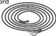 | 1 |
| 2 | Installation plate fixing screw | 6 | |||
| 3 | Remote Cont  | 1 | 8 |  | 4 |
| 4 | Battery 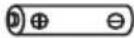 | 2 | 9 | PM 0.1 Filter | 1 |
| 5 | Remote control holder fixing screw  | 2 | |||
| 6 | Remote control holder  | 1 | |||
* For specific model only
| Applicable piping kit | Piping size | |
| Gas | Liquid | |
| CZ-3F5, 7EN | 9.52 mm (3/8") | 6.35 mm (1/4") |
| CZ-4F5, 7, 10AN | 12.7 mm (1/2") | 6.35 mm (1/4") |
| CZ-52F5, 10AN | 15.88 mm (5/8") | 6.35 mm (1/4") |
SELECT THE BEST LOCATION
INDOOR UNIT
☐ Do not install the unit in excessive oil fume area such as kitchen, workshop and etc.
☐ There should not be any heat source or steam near the unit.
There should not be any obstacles blocking the air circulation.
☐ A place where air circulation in the room is good.
☐ A place where drainage can be easily done.
☐ A place where noise prevention is taken into consideration.
☐ Do not install the unit near the door way.
☐ Ensure the spaces indicated by arrows from the wall, ceiling, fence or other obstacles.
☐ Recommended installation height for indoor unit shall be at least 2.5 m.
OUTDOOR UNIT
☐ If an awning is built over the unit to prevent direct sunlight or rain, be careful that heat radiation from the condenser is not obstructed.
☐ There should not be any animal or plant which could be affected by hot air discharged.
☐ Keep the spaces indicated by arrows from wall, ceiling, fence or other obstacles.
☐ Do not place any obstacles which may cause a short circuit of the discharged air.
☐ If piping length is over the [piping length for additional gas), additional refrigerant should be added as shown in the table.
Table A
| Model | Piping Size | *Std Length (m) | Max Elevation (m) | Min Piping Length (m) | Max Piping Length (m) | Additional Refrigerant (g/m) | Piping Length for add. Gas (m) | |
| Gas | Liquid | |||||||
| RU9*** Series RU12*** Series | 9.52mm (3/8") | 6.35mm (1/4") | 5 | 5 | 3 | 10 | 10 | 7.5 |
| RU18*** Series | 12.7mm (1/2") | 6.35mm (1/4") | 10 | 3 | 15 | 15 | 7.5 | |
Example : For RU12***
if the unit is installed at 10m distance, the quantity of additional refrigerant should be 25g..... (10 - 7.5)m x 10g/m = 25g.
Indoor/Outdoor Unit Installation Diagram

Attention not to bend up drain hose

WARNING
Flare connection only at outside of building

| >100% |
English
Information for Users on Collection and Disposal of Old Equipment and used Batteries
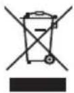
[Information on Disposal in other Countries outside the European Union] These symbols are only valid in the European Union. If you wish to discard these items, please contact your local authorities or dealer and ask for the correct method of disposal.


Note for the battery symbol (bottom two symbol examples):
This symbol might be used in combination with a chemical symbol. In this case it complies with the requirement set by the Directive for the chemical involved.

- Panasonic®
- Operating & Installation Instructions
- Installation & Operating Instructions Air Conditioner
- Quick guide
- Inserting the batteries
- Basic operation
- Table of Contents
- Installation Instructions
- Accessories
- Note:
- Safety precautions
- WARNING
- CAUTION
- Indoor unit and outdoor unit
- Remote control
- Power supply
- Precaution for using R32 refrigerant
- Installation (Space)
- Servicing
- 2-1. Service personnel
- 2-2. Work
- 2-3. Checking for presence of refrigerant
- 2-4. Presence of fire extinguisher
- 2-5. No ignition sources
- 2-6. Ventilated area
- 2-7. Checks to the refrigeration equipment
- 2-8. Checks to electrical devices
- Repairs to sealed components
- Repair to intrinsically safe components
- Cabling
- Detection of flammable refrigerants
- Leak detection methods
- Removal and evacuation
- Charging procedures
- Decommissioning
- Labelling
- Recovery
- How to use
- MODE
- To select operation mode
- AUTO - For your convenience
- COOL - To enjoy cool air
- DRY - To dehumidify the environment
- FAN - To operate Air-Con in "Fan Only" mode
- SLEEP
- To maximise comfort while sleeping
- To adjust horizontal airflow direction
- Auto OFF/ON button
- How to use (For COOLING Models)
- To select fan speed
- To adjust vertical airflow direction
- To clean dust on Evap. Coil of the Air-Conditioner Unit
- To reach temperature quickly
- To Select ECO
- Auto Restart Control
- To set the timer
- Operation conditions
- To Learn more...
- To select different Performance modes
- Cleaning instructions
- Indoor unit
- Front panel
- Dust filters
- Every 2 weeks
- For seasonal inspection after extended non-use
- For extended non-use
- Troubleshooting
- NON SERVICEABLE CRITERIAS
- Notes
- SELECT THE BEST LOCATION
- HOW TO FIX INSTALLATION PLATE
- TO DRILL A HOLE IN THE WALL AND INSTALL A SLEEVE OF PIPING
- INDOOR UNIT INSTALLATION
- FOR THE RIGHT REAR PIPING
- Step-1
- Step-2
- Step-3
- Step-4
- FOR THE RIGHT AND RIGHT BOTTOM PIPING
- Right Rear piping
- Right and Right Bottom piping
- FOR THE EMBEDDED PIPING
- Step-1 Replace the drain hose
- Step-2 Bend the embedded piping
- Step-3 Pull the connection cable into Indoor Unit
- Step-4 Cut and flare the embedded piping
- Step-5 Install the Indoor Unit
- Step-6 Connect the piping
- Step-7 Insulate and nish the piping
- Step-8 Secure the Indoor Unit
- Install the indoor unit
- Secure the Indoor Unit
- Insert the connection cable
- (Drain pipe to be assemble on right rear drain position only)
- HOW TO DETACH INSTALLATION PLATE
- 5
- CONNECT THE CABLE TO THE INDOOR UNIT
- WIRE STRIPPING, CONNECTING REQUIREMENT
- CUTTING AND FLARING THE PIPING
- OUTDOOR UNIT
- 1
- 2
- INSTALL THE OUTDOOR UNIT
- 3
- CONNECT THE PIPING
- Connecting The Piping to Indoor
- Connecting The Piping to Outdoor
- EVALUATION OF THE PERFORMANCE
- Pump Down Method When Reuse Existing Piping (R22 Model) for R32 Model
- Possibility of Mixing
- To Reuse Old Piping
- Proper Pump Down Method
- CHECK ITEMS
- CONNECT THE CABLE TO THE OUTDOOR UNIT
- 6
- PIPING INSULATION
- HOW TO TAKE OUT FRONT GRILLE
- AUTO SWITCH OPERATION
- CHECK THE DRAINAGE
- INSTALLATION OF PM 0.1 FILTER
- Safety Precautions while Installation
- Information for Users on Collection and Disposal of Old Equipment and used Batteries
Merek : PANASONIC
Model : CS-RU12AKD
Kategori : 8