250.2 - 12617 Glemm - Panduan pengguna gratis
Temukan panduan perangkat secara gratis 250.2 Glemm dalam format PDF.

Pertanyaan pengguna tentang 250.2 Glemm
0 pertanyaan tentang perangkat ini. Jawab yang Anda tahu atau ajukan milik Anda sendiri.
Ajukan pertanyaan baru tentang perangkat ini
Unduh instruksi untuk 12617 dalam format PDF gratis! Temukan panduan Anda 250.2 - Glemm dan ambil kembali perangkat elektronik Anda. Di halaman ini diterbitkan semua dokumen yang diperlukan untuk penggunaan perangkat Anda. 250.2 merek Glemm.
PANDUAN PENGGUNA 250.2 Glemm

Without OT series
User's Manual
natural_image
Front view of a black industrial server rack unit with ventilation grilles and indicator lights (no visible text or symbols)125.2
natural_image
Front view of a black industrial rack unit labeled '125.4' with ventilation grilles and branding (no readable text beyond labels)125.4
natural_image
Front view of a black server rack unit labeled '250.2' with ventilation grilles (no readable text beyond branding)250.2
natural_image
Front view of a black industrial server rack unit (no visible text or labels)250.4
SAFETY RELATED SYMBOLS

The symbol is used to indicate that some hazardous live terminals are involved within this apparatus, even under the normal operating conditions.

The symbol is used in the service documentation to indicate that specific component shall be only replaced by the component specified in that Documentation for safety reasons.
Protective grounding terminal.
\~ Alternating current /voltage.
Hazardous live terminal.
ON: Denotes the apparatus turns on.
OFF: Denotes the apparatus turns off, because of using the single pole switch, be sure to unplug the AC power to prevent any electric shock before you proceed your service.
WARNING: Describes precautions that should be observed to prevent the danger of injury or death to the user.

Disposing of this product should not be placed in municipal waste and should be separate collection.
CAUTION: Describes precautions that should be observed to prevent danger of the apparatus.
WARNING
- Power Supply
Ensure the source voltage matches the voltage of the power supply before turning
Unplug this apparatus during lightning storms or when unused for long periods of time.
- External Connection
The external wiring connected to the output hazardous live terminals requires installation by an instructed person, or the use of ready-made leads or cords.
- Do not Remove any Cover
There are maybe some areas with high voltages inside, to reduce the risk of electric shock, do not remove any cover if the power supply is connected.
The cover should be removed by the qualified personnel only.
No user serviceable parts inside.
- Fuse
To prevent a fire, make sure to use fuses with specified standard (current, voltage, type). Do not use a different fuse or short circuit the fuse holder.
Before replacing the fuse, turn OFF the apparatus and disconnected the power source.
- Protective Grounding
Before turning the product ON, make sure that it is connected to Ground. This is to prevent the risk of electric shock. Never cut internal or external Ground wires. Likewise, never remove Ground wiring from the Protective Ground Terminal.
Never cut off the internal or external protective grounding wire or disconnect the wiring of protective grounding terminal.
The apparatus shall be connected to a mains socket outlet with a protective earthing connection.
- Operating Conditions
This apparatus shall not be exposed to dripping or splashing and that no objects filled with liquids, such as vases, shall be placed on this apparatus.
To reduce the risk of fire or electric shock, do not expose this apparatus to rain or moisture.
Do not use this apparatus near water. Install in accordance with the manufacture-r's instructions. Do not install near any heat sources such as radiators, heat registers, stoves, or other apparatus (including amplifiers) that produce heat. Do not block any ventilation openings.
No naked flame sources, such as lighted candles, should be placed on the apparatus.
IMPORTANT SAFETY INSTRUCTIONS
- Read these instructions.
- Follow all instructions.
- Keep these instructions.
- Heed all warnings.
- Only use attachments/accessories specified by the manufacturer.
• Power Cord and Plug
Do not defeat the safety purpose of the polarized or grounding type plug.
The mains plug is used as the disconnecting device, the disconnecting device shall remain readily operable.
A polarized plug has two blades with one wider than the other. A grounding type plug has two blades and a third grounding prong. The wide blade or the third prong are provided for your safety. If the provided plug does not fit into your outlet, consult an electrician for replacement of the obsolete outlet.
Protect the power cord from being walked on or pinched particularly at plugs, convenience receptacles, and the points where they exit from the apparatus.
- Cleaning
When the apparatus needs a cleaning, you can blow off dust from the apparatus with a blower or clean with rag etc.
Don't use solvents such as benzol, alcohol, or other fluids with very strong volatility and flammability for cleaning the apparatus body. Clean only with dry cloth.
- Servicing
Refer all servicing to qualified personnel. To reduce the risk of electric shock, do not perform any servicing other than that contained in the operating instructions unless you are qualified to do so.
Servicing is required when the apparatus has been damaged in any way, such as power supply cord or plug is damaged, liquid has been spilled or objects have fallen into the apparatus, the apparatus has been exposed to rain or moisture, does not operate normally, or has been dropped.
TABLE OF CONTENTS
I.FUNCTIONAL CHARACTERISTICS DESCRIPTION......
2.FRONT PANEL....2
3. REAR PANEL....3
4. TECHNICAL SPECIFICATIONS....4
5. INPUT AND OUTPUT CNNECTION DIAGRAN....5
6.WIRING DIAGRAN 15
I.FUNCTIONAL CHARACTERISTICS DESCRIPTION
Without OT series is pure after level power amplifier, suitable for professional music playing and public address system.
The main function and characteristics:
I, The PA amplifier without output transformer, can output 4 ohm / 70 V / 100 V.
2, 4 ohm / 70 V / 100 V output can be through the selector switch control.
3. Each channel has independent balance input terminal.
4, Each channel has the independence the volume control knob.
5, Input can select MONO or DUAL.
6. Can choose broadband output or L/H CUT.
7, The channel independent SIG, 4 ohm, 70 v, 100 v, PRO instructions.
8, With temperature protection, output overload protection and DC protection function.
9, Have professional sound quality of the power amplifier and PA PA remote transmission function.
10, Concise and beautiful appearance, which can be put in system collocation.
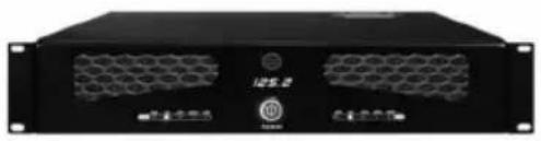
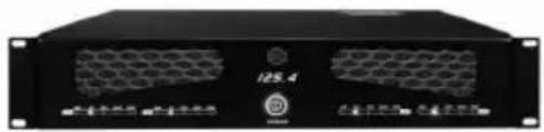
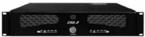
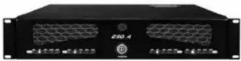
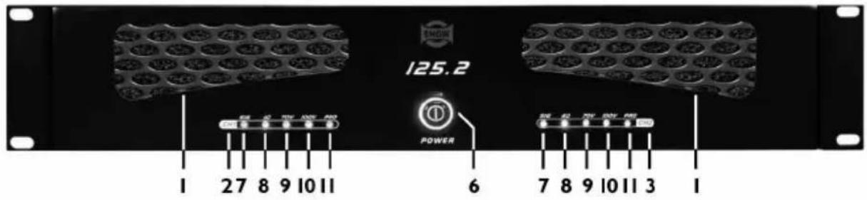
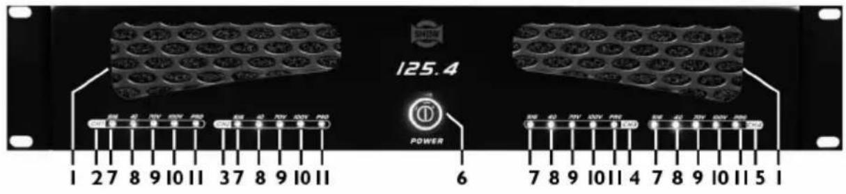
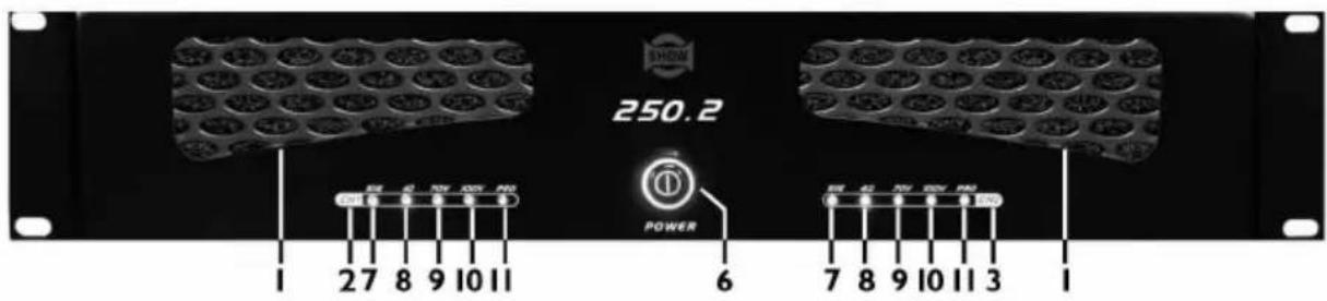
2.FRONT PANEL
1).125.2
2).125.4
3).250.2
4).250.4
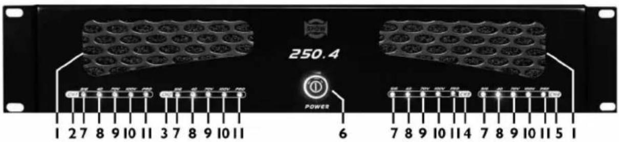
Notice: I.IN THE WIND WINDOW DISPLAY
3.CH2 LED DISPLAY
5.CH4 LED DISPLAY.
7.SIGNAL DISPLAY
9.70V OUTPUT DISPLAY
11.PROTECT DISPLAY
2.CHI LED DISPLAY
4.CH3 LED DISPLAY
- POWER SWITH
8.4Ω OUTPUT DISPLAY
10.100V OUTPUT DISPLAY
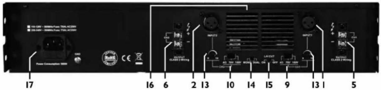
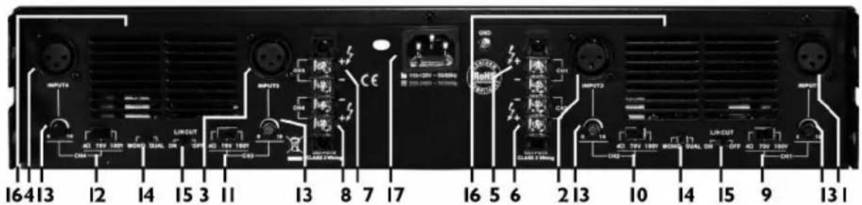
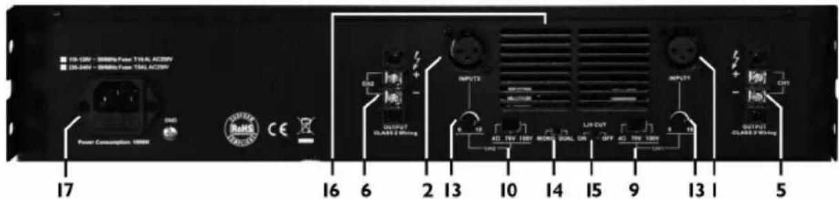
3.REAP PANL
1).125.2
2).125.4
3).250.2
4).250.4
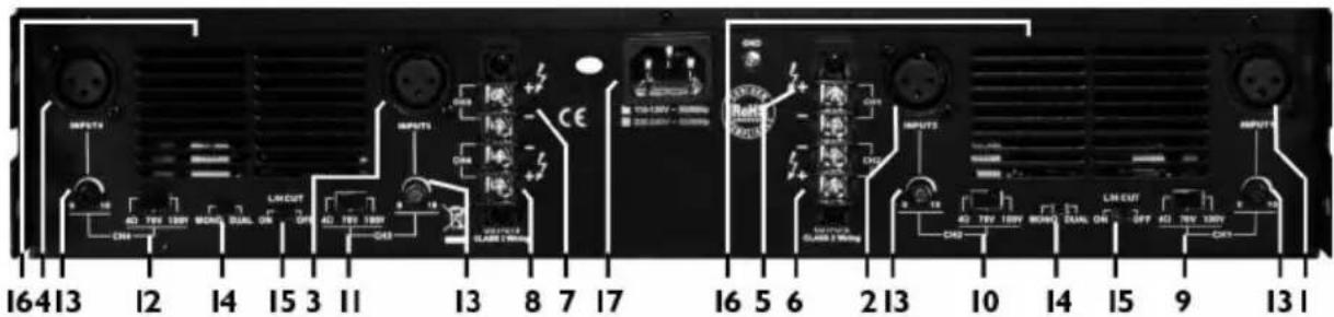
Notice:1.CHI INPUT
3.CH3 INPUT
5.CHI OUTPUT
7.CH3 OUTPUT
9.CHI OUTPUT SELECT(4Ω/70V/100V)
11.CH3 OUTPUT SELECT(4Ω/70V/100V)
13.VOLUME CONTROL(CHI-CH4)
15.L/H CUT(ON/OFF)
17.AC INPUT
2.CH2 INPUT
4.CH4 INPUT
6.CH2 OUTPUT
8.CH4 OUTPUT
10.CH2 OUTPUT SELECT(4Ω/70V/100V)
12.CH4 OUTPUT SELECT(4Ω/70V/100V)
- MONO/DUAL
16.OUT OF THE WIND WINDOW
4.TECHNICAL SPECIFICATIONS
| MODEL | 125.2 / 250.2 | 125.4 / 250.4 |
| Power output (1kHz / 4Ω): | RMS 125W*2 / 250W*2 | RMS 125W*4 / 250W*4 |
| Frequency response: | L/H CUT OFF 20Hz - 20kHz / L/H CUT ON 200Hz - 10kHz (±1dB) | L/H CUT OFF 20Hz - 20kHz / L/H CUT ON 200Hz - 10kHz (±1dB) |
| Power supply : | AC 115V / 230V 50Hz / 60Hz | AC 115V / 230V 50Hz / 60Hz |
| Inputs (balance / 1kHz): | 0 ± 1.5 dBv | 0 ± 1.5 dBv |
| Maximum Input Level (balance / 1kHz) | 20dBv ± 1.5dBv | 20dBv ± 1.5dBv |
| THD+N (1kHz / -3dBv) : | < 0.1% | < 0.1% |
| S / N Ratio: | >95 dB | >95 dB |
| CMRR (balance / 1kHz) : | >60dB | >60dB |
| Crosstalk (1kHz) : | >60dB | >60dB |
| Outputs : | 4Ω/70V / 100V switchable | 4Ω/70V / 100V switchable |
| Dimension (W x D x H) : | 434mm x 353mm x 88.5mm(17.1" x 13.9" x 3.5") | 434mm x 425mm x 88.5mm(17.1" x 16.7" x 3.5") |
| Weight (Approx.) : | 6.9kg (15.2lbs) / 7.5kg (16.53bs) | 9.2kg (20.28bs) / 9.8kg (21.60bs) |
5. INPUT AND OUTPUT CONNECTION DIGGRAN
Figure 1:
CH1/CH2 loaded with 4Ω, dual channel input:
I. Select "MONO/DUAL" at "DUAL" position, dual channel input;
2. CH1/CH2 output select at "4Ω" position, both loaded with 4Ω;
3. Select "L/H CUT" at "OFF" position, for music broadcast to improve quality;

flowchart
graph TD
    A["Power Consumption: 300W"] --> B["Speaker 1"]
    C["Speaker 2"] --> D["Dual Channel Input"]
    E["Speaker 3"] --> D
    B --> F["Output Selection at "4Ω" position"]
    D --> G["Select "L/H CUT" at "OFF" position"]
    D --> H["L/H CUT at "DUAL" position"]
    D --> I["Monohual Dual ON OFF"]
    D --> J["Output Select at "4Ω" position"]
    style A fill:#f9f,stroke:#333
    style C fill:#f9f,stroke:#333
    style E fill:#f9f,stroke:#333
    style B fill:#ccf,stroke:#333
    style D fill:#ccf,stroke:#333
    style F fill:#dfd,stroke:#333
    style G fill:#dfd,stroke:#333
    style H fill:#dfd,stroke:#333
    style I fill:#dfd,stroke:#333
    style J fill:#dfd,stroke:#333
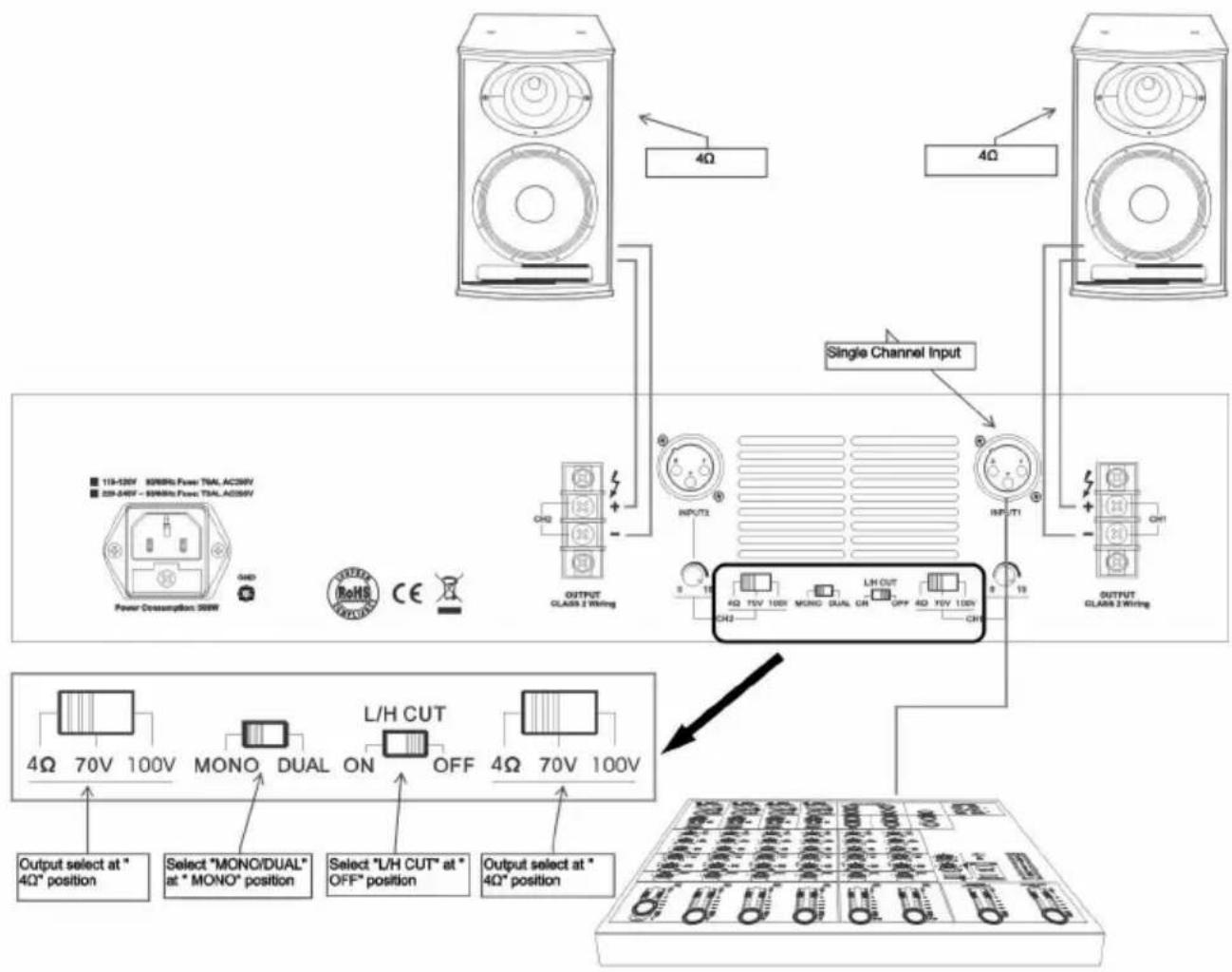
Figure 2:
CH1/CH2 loaded with 4Ω, single channel input:
I. Select "MONO/DUAL" at "MONO" position, single channel input;
2. CHI/CH2 output select at "4Ω" position, both loaded with 4Ω;
3. Select "L/H CUT" at "OFF" position, for music broadcast to improve quality;
flowchart
graph TD
    A["Speaker Units"] -->|4Ω| B["Single Channel Input"]
    C["Speaker Units"] -->|4Ω| B
    D["Power Consumption 200W"] --> E["Output Selection Panel"]
    F["OUTPUT CLASS 2 Wiring"] --> G["L/H CUT"]
    H["INPUT 12"] --> I["4Ω 15V 100V MONO DUAL ON OFF 4Ω 70V 100V"]
    J["CH3"] --> K["Select "MONO/DUAL" at "MONO" position"]
    L["CH3"] --> M["Select "L/H CUT" at "OFF" position"]
    N["CH3"] --> O["Output Select at "4Ω" position"]
    P["4Ω"] --> Q["Output Select at "4Ω" position"]
    R["4Ω"] --> S["Output Select at "4Ω" position"]
Figure 3:
CH1 loaded with 100V, CH2 loaded with 4Ω, dual channel input:
I. Select "MONO/DUAL" at "DUAL" position, dual channel input;
2. CHI output select at "100V" position, loaded with rated 100V speaker; CH2 output select at "4Ω" position, loaded with 4Ω;
- Select "L/H CUT" at "ON" position, to prevent low frequency protection and improve the transmission efficiency. Applicable to Public Address System;
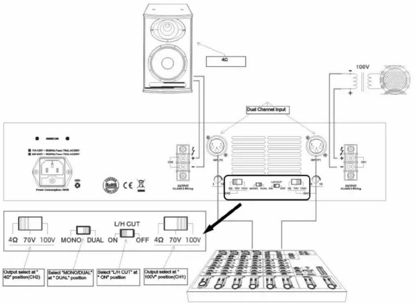
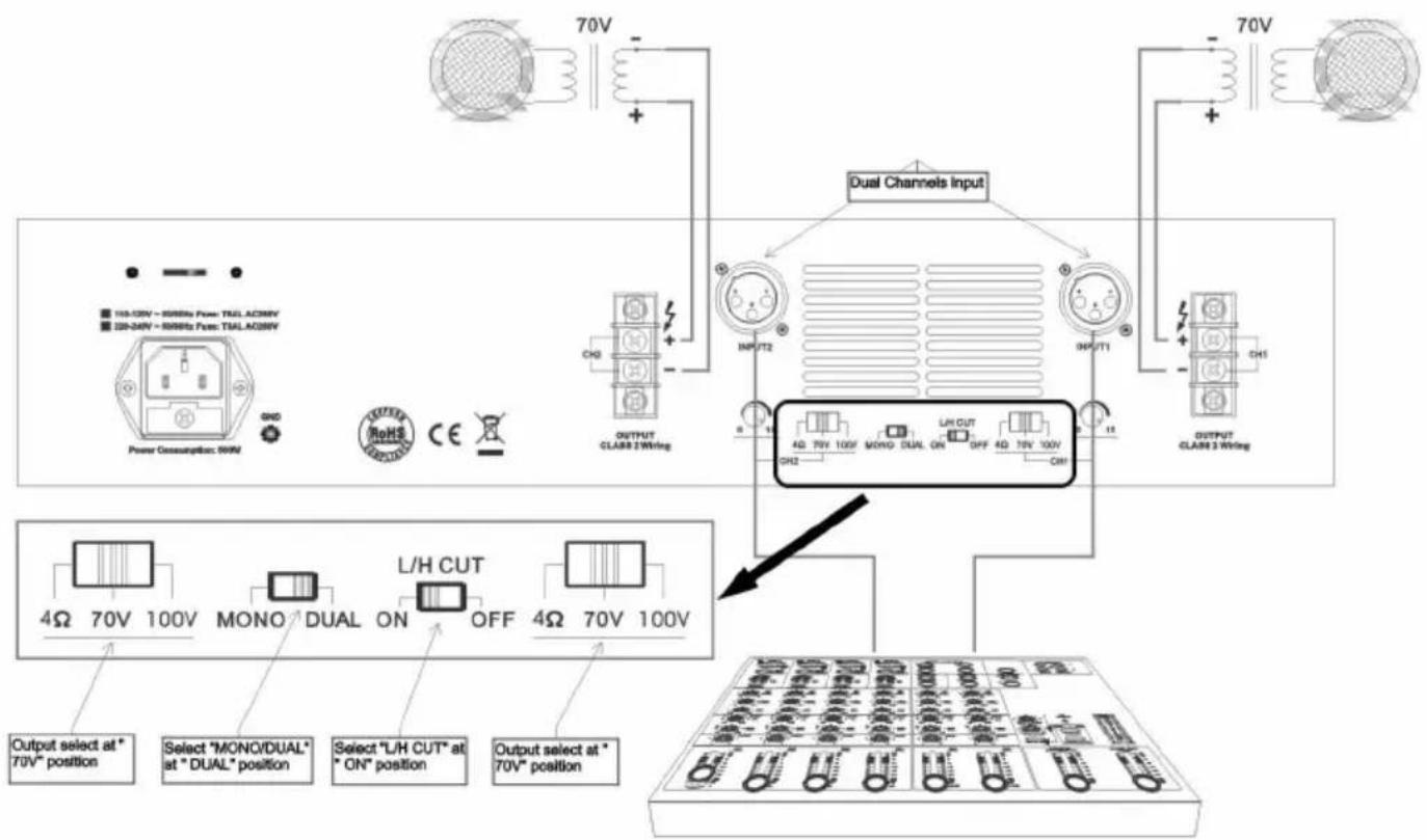
Figure 4:
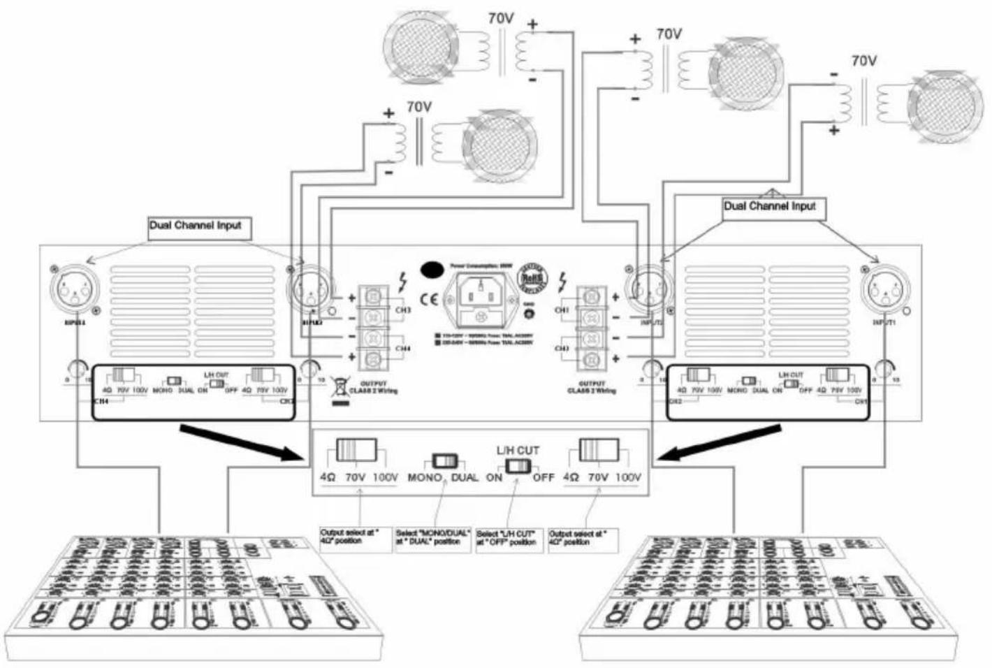
CH1/CH2 loaded with 70V, dual channel input:
I. Select "MONO/DUAL" at "DUAL" position, dual channel input;
-
CH1/CH2 output select at "70V" position, both loaded with rated 70V speaker;
-
Select "L/H CUT" at "ON" position, to prevent low frequency protection and improve the transmission efficiency. Applicable to Public Address System;
flowchart
graph TD
    A["Power Consumption: 50kW"] --> B["70V"]
    B --> C["+"]
    C --> D["Dual Channels Input"]
    D --> E["Output CLABR 2 Wiring"]
    E --> F["70V"]
    F --> G["+"]
    G --> H["Dual Channels Input"]
    H --> I["Output CLABR 3 Wiring"]
    I --> J["70V"]
    J --> K["+"]
    K --> L["Dual Channels Input"]
    L --> M["Output CLABR 2 Wiring"]
    M --> N["70V"]
    N --> O["+"]
    O --> P["Dual Channels Input"]
    P --> Q["Output CLABR 3 Wiring"]
    Q --> R["70V"]
    R --> S["+"]
    S --> T["Dual Channels Input"]
    T --> U["Output CLABR 2 Wiring"]
    U --> V["70V"]
    V --> W["+"]
    W --> X["Dual Channels Input"]
    X --> Y["Output CLABR 3 Wiring"]
    Y --> Z["70V"]
    Z --> AA["+"]
    AA --> AB["Dual Channels Input"]
    AB --> AC["Output CLABR 2 Wiring"]
    AC --> AD["70V"]
    AD --> AE["+"]
    AE --> AF["Dual Channels Input"]
    AF --> AG["Output CLABR 3 Wiring"]
    AG --> AH["70V"]
Figure 5:
CH1/CH2 loaded with 100V, dual channelinput:
I. Select "MONO/DUAL" at "DUAL" position, dual channel input;
2. CHI/CH2 output select at "100V" position, both loaded with rated 100V speaker;
3. Select "L/H CUT" at "ON" position, to prevent low frequency protection and improve the transmission efficiency. Applicable to Public Address System;
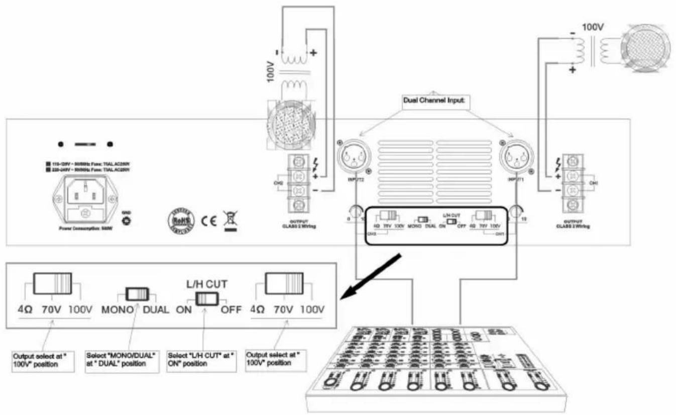
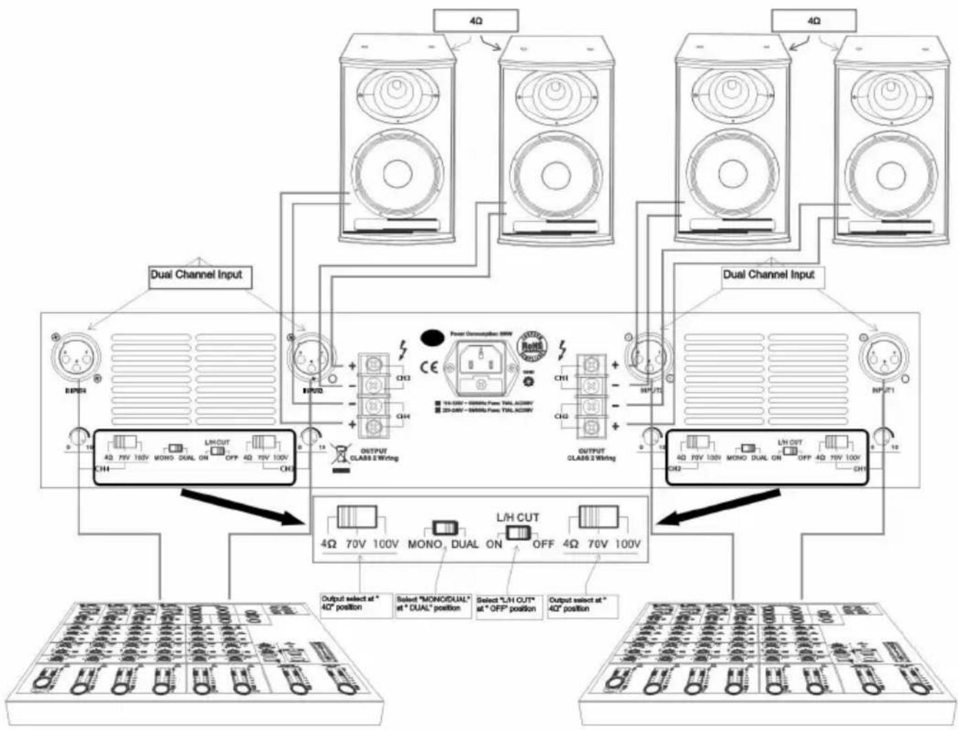
Figure 6:
CH1/CH2/CH3/CH4 loaded with 4Ω, dual channel input:
I. Select "MONO/DUAL" at "DUAL" position, dual channel input;
2. CHI/CH2/CH3/CH4 output select at "4Ω" position, both loaded with 4Ω;
3. Select "L/H CUT" at "OFF" position, for music broadcast to improve quality;
flowchart
graph TD
    A["4Ω"] --> B["Dual Channel Input"]
    C["4Ω"] --> D["Dual Channel Input"]
    E["4Ω"] --> F["Dual Channel Input"]
    G["4Ω"] --> H["Dual Channel Input"]
    I["4Ω"] --> J["Dual Channel Input"]
    K["4Ω"] --> L["Dual Channel Input"]
    M["4Ω"] --> N["Dual Channel Input"]
    O["4Ω"] --> P["Dual Channel Input"]
    Q["4Ω"] --> R["Dual Channel Input"]
    S["4Ω"] --> T["Dual Channel Input"]
    U["4Ω"] --> V["Dual Channel Input"]
    W["4Ω"] --> X["Dual Channel Input"]
    Y["4Ω"] --> Z["Dual Channel Input"]
    AA["4Ω"] --> AB["Dual Channel Input"]
    AC["4Ω"] --> AD["Dual Channel Input"]
    AE["4Ω"] --> AF["Dual Channel Input"]
    AG["4Ω"] --> AH["Dual Channel Input"]
    AI["4Ω"] --> AJ["Dual Channel Input"]
    AK["4Ω"] --> AL["Dual Channel Input"]
    AM["4Ω"] --> AN["Dual Channel Input"]
    AO["4Ω"] --> AP["Dual Channel Input"]
    AQ["4Ω"] --> AR["Dual Channel Input"]
    AS["4Ω"] --> AT["Dual Channel Input"]
    AU["4Ω"] --> AV["Dual Channel Input"]
    AW["4Ω"] --> AX["Dual Channel Input"]
    AY["10V 70V 100V MONO DUAL ON OFF 4Ω 70V 100V CHI"] --> AU
    AX --> AU
    AU --> AV
    AV --> AW
    AW --> AX
    AX --> AU
    style A fill:#f9f,stroke:#333
    style C fill:#f9f,stroke:#333
    style E fill:#f9f,stroke:#333
    style G fill:#f9f,stroke:#333
    style AF fill:#f9f,stroke:#333
    style AG fill:#f9f,stroke:#333
    style AH fill:#f9f,stroke:#333
    style AI fill:#f9f,stroke:#333
    style AJ fill:#f9f,stroke:#333
    style AK fill:#f9f,stroke:#333
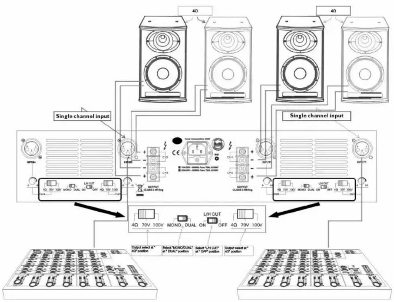
Figure 7:
CH1/CH2 /CH3/CH4 loaded with 4Ω, single channel input:
I. Select "MONO/DUAL" at "MONO" position, single channel input;
2. CH1/CH2/CH3/CH4 output select at "4Ω" position, both loaded with 4Ω;
3. Select "L/H CUT" at "OFF" position, for music broadcast to improve uality;
flowchart
graph TD
    A["Single channel input"] --> B["Ch1"]
    A --> C["Ch2"]
    A --> D["Ch3"]
    E["Output select at 40° position"] --> F["4Ω 70V 100V"]
    G["Select "MOND/DUAL" at 4" DUAL" position"] --> H["4Ω 70V 100V"]
    I["Select "L/H CUT" at 4" OFF" position"] --> J["4Ω 70V 100V"]
    K["Output select at 40° position"] --> L["4Ω 70V 100V"]
    M["Power consumption: 50W"] --> N["CH3"]
    O["Class 3 W/Hing"] --> P["OUTPUT CLASS 3 W/Hing"]
    Q["CH3"] --> R["CH2"]
    S["CH1"] --> T["CH2"]
    U["CH2"] --> V["CH3"]
    W["CH3"] --> X["CH2"]
    Y["CH3"] --> Z["CH2"]
    AA["CH3"] --> AB["CH2"]
    AC["CH3"] --> AD["CH2"]
    AE["CH3"] --> AF["CH2"]
    AG["CH3"] --> AH["CH2"]
    AI["CH3"] --> AJ["CH2"]
    AK["CH3"] --> AL["CH2"]
    AM["CH3"] --> AN["CH2"]
    AO["CH3"] --> AP["CH2"]
    AQ["CH3"] --> AR["CH2"]
    AS["CH3"] --> AT["CH2"]
    AU["CH3"] --> AV["CH2"]
    AW["CH3"] --> AX["CH2"]
    AY["4Ω 70V 100V"] --> Z
    AZ["4Ω 70V 100V"] --> AA
    BA["4Ω 70V 100V"] --> AB
    BB["4Ω 70V 100V"] --> AC
    BC["4Ω 70V 100V"] --> AD
    BE["4Ω 70V 100V"] --> AE
    BF["4Ω 70V 100V"] --> AG
    BH["4Ω 70V 100V"] --> AI
    AJ["4Ω 70V 100V"] --> AK
    AL["4Ω 70V 100V"] --> AM
    AN["4Ω 70V 100V"] --> AU
    AO["4Ω 70V 100V"] --> AV
    AW["4Ω 70V 100V"] --> AX
    AY["4Ω 70V 100V"] --> AZ
    AZ --> BA
    BB --> BB
    AC --> AC
    AD --> AC
    AE --> AE
    AF --> AF
    AG --> AG
    AH --> AH
    AI --> AI
    AJ --> AJ
    AK --> AK
    AL --> AL
    AM --> AL
    AN --> AN
    AO --> AO
    AP --> AP
    AQ --> AQ
    AR --> AR
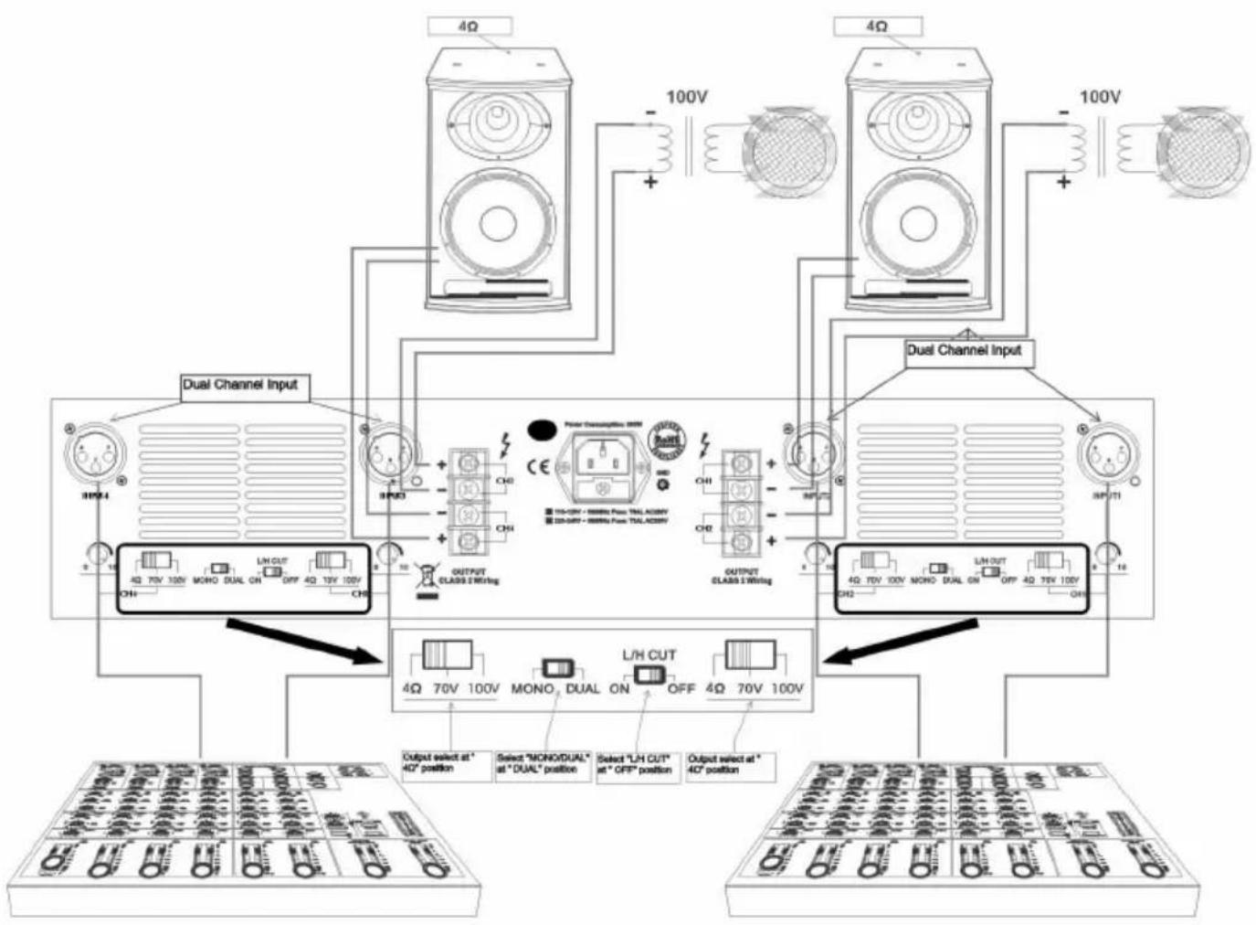
Figure 8:
CH2/CH3 loaded with 100V, CH1/CH4 loaded with 4Ω, dual channel input:
I. Select "MONO/DUAL" at "DUAL" position, dual channel input;
2. CH2/CH3 output select at "100V" position, loaded with rated 100V speaker;
CHI/CH4 output select at "4Ω" position, loaded with 4Ω;
- Select "L/H CUT" at "ON" position, to prevent low frequency protection and improve the transmission efficiency. Applicable to Public Address System;
flowchart
graph TD
    A["4Ω"] --> B["100V"]
    C["4Ω"] --> D["100V"]
    E["Dual Channel Input"] --> F["OUTPUT CLASS I Wiring"]
    F --> G["4Ω 70V 100V MONO DUAL ON OFF 4Q 13V 100V CHI"]
    F --> H["4Ω 70V 100V L/H CUT ON OFF 4Q 70V 100V CHI"]
    I["Dual Channel Input"] --> J["OUTPUT CLASS I Wiring"]
    J --> K["4Ω 70V 100V MONO DUAL ON OFF 4Q 75V 100V CHI"]
    I --> L["4Ω 70V 100V L/H CUT ON OFF 4Q 75V 100V CHI"]
    M["Output select at 40° position"] --> N["Select "MONO/DUAL" at "DUAL" position"]
    M --> O["Select "L/H CUT" at "OFF" position"]
    M --> P["Output select at 40° position"]
Figure 9:
CH1/CH2 /CH3/CH4 loaded with 70V, dual channel input:
I. Select "MONO/DUAL" at "DUAL" position, dual channel input;
2. CH1/CH2/CH3/CH4 output select at "70V" position, both loaded with rated 70V speaker;
3. Select "L/H CUT" at "ON" position, to prevent
low frequency protection and improve the transmission efficiency.
Applicable to Public Address System;
flowchart
graph TD
    A["Dual Channel Input"] --> B["Ch1"]
    A --> C["Ch2"]
    A --> D["Ch3"]
    A --> E["Ch4"]
    A --> F["Output CLAS8 2 Wiring"]
    G["Dual Channel Input"] --> H["Ch1"]
    G --> I["Ch2"]
    G --> J["Ch3"]
    G --> K["Ch4"]
    G --> L["Output CLAS8 2 Wiring"]
    M["Output select at * 4Ω position"] --> N["LH CUT"]
    O["Select "MONO/DUAL" at "DUAL" position"] --> P["LH CUT"]
    Q["Select "LH CUT" at "OFF" position"] --> R["LH CUT"]
    S["Output select at * 4Ω position"] --> T["LH CUT"]
    U["Input 1"] --> V["INFLUT2"]
    V --> W["INFLUT1"]
    X["Input 2"] --> Y["INFLUT1"]
    Z["Input 3"] --> AA["INFLUT1"]
Figure 10:
CH1/CH2/CH3/CH4 loaded with 100V, dual channel input:
I. Select "MONO/DUAL" at "DUAL" position, dual channel input;
2. CH1/CH2/CH3/CH4 output select at "100V" position, both loaded with rated 100V speaker;
3. Select "L/H CUT" at "ON" position, to prevent low frequency protection and improve the transmission efficiency. Applicable to Public Address System;

flowchart
graph TD
    A["Power Connections: 10V"] --> B["Dual Channel Input"]
    B --> C["Output select at 40° position"]
    B --> D["Select "MONO/DUAL" at "DUAL" position"]
    B --> E["Select "LH CUT" at "OFF" position"]
    B --> F["Output select at 40° position"]
    G["CH1"] --> H["Dual Channel Input"]
    I["CH2"] --> J["Dual Channel Input"]
    K["CH3"] --> L["Output Select at 40° position"]
    M["CH4"] --> N["Output Select at 40° position"]
    O["CH5"] --> P["Output Select at 40° position"]
    Q["CH6"] --> R["Output Select at 40° position"]
    S["CH7"] --> T["Output Select at 40° position"]
    U["CH8"] --> V["Output Select at 40° position"]
    W["CH9"] --> X["Output Select at 40° position"]
    Y["CH10"] --> Z["Output Select at 40° position"]
    AA["CH11"] --> AB["Output Select at 40° position"]
    AC["CH12"] --> AD["Output Select at 40° position"]
    AE["CH13"] --> AF["Output Select at 40° position"]
    AG["CH14"] --> AH["Output Select at 40° position"]
    AI["CH15"] --> AJ["Output Select at 40° position"]
    AK["CH16"] --> AL["Output Select at 40° position"]
    AM["CH17"] --> AN["Output Select at 40° position"]
    AO["CH18"] --> AP["Output Select at 40° position"]
    AQ["CH19"] --> AR["Output Select at 40° position"]
    AS["CH20"] --> AT["Output Select at 40° position"]
    AU["CH21"] --> AV["Output Select at 40° position"]
    AW["CH22"] --> AX["Output Select at 40° position"]
    AY["Input"] --> BY["Dual Channel Input"]
    AZ["Dual Channel Input"] --> BA["Dual Channel Input"]
6.WIRING DIAGRAM
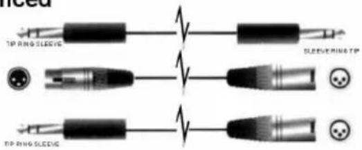
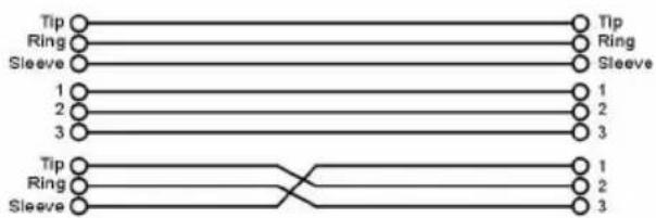
• Balanced
flowchart
graph TD
    A["Tip"] --> B["Ring"]
    B --> C["Sleeve"]
    D["1"] --> E["2"]
    F["3"] --> G["3"]
    H["Tip"] --> I["Ring"]
    I --> J["Sleeve"]
    K["1"] --> L["2"]
    M["3"] --> N["3"]
    O["1"] --> P["2"]
    Q["3"] --> R["3"]
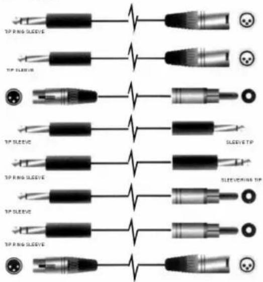
- Unbalanced
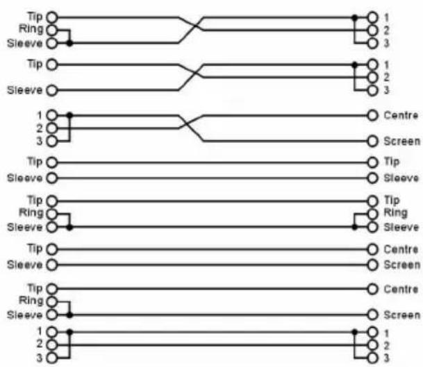
flowchart
graph TD
    A["Tip"] --> B["Ring"]
    A --> C["Sleeve"]
    D["Tip"] --> E["Ring"]
    D --> F["Sleeve"]
    G["1"] --> H["Centre"]
    I["2"] --> J["Screen"]
    K["3"] --> L["Screen"]
    M["Tip"] --> N["Tip"]
    O["Sleeve"] --> P["Sleeve"]
    Q["Tip"] --> R["Ring"]
    S["Sleeve"] --> T["Sleeve"]
    U["Tip"] --> V["Centre"]
    W["Sleeve"] --> X["Screen"]
    Y["Tip"] --> Z["Centre"]
    AA["Sleeve"] --> AB["Screen"]
SEIKAKU TECHNICAL GROUP LIMITED
SEKAKU ELECTRON INDUSTRY (D.G.) CO. LTD.
West City Science Park Heng Li town, Dong Guan City, Guang Dong
Tel:86-0769-3721369 Fax:86-0769-3721330
http://www.show-pa.com.cn e-mail: sekaku@sekaku.com
All rights reserved to SEIKAKU. All features and content might be changed without prior notice. Any photocopy, translation, or reproduction of part of this manual without written permission is forbidden. Copyright © 2005 Seikaku Group