10BHDM384 - 17756 Daytronic - Panduan pengguna gratis
Temukan panduan perangkat secara gratis 10BHDM384 Daytronic dalam format PDF.

Pertanyaan pengguna tentang 10BHDM384 Daytronic
0 pertanyaan tentang perangkat ini. Jawab yang Anda tahu atau ajukan milik Anda sendiri.
Ajukan pertanyaan baru tentang perangkat ini
Unduh instruksi untuk 17756 dalam format PDF gratis! Temukan panduan Anda 10BHDM384 - Daytronic dan ambil kembali perangkat elektronik Anda. Di halaman ini diterbitkan semua dokumen yang diperlukan untuk penggunaan perangkat Anda. 10BHDM384 merek Daytronic.
PANDUAN PENGGUNA 10BHDM384 Daytronic
SYSTEM 10 GUIDEBOOK
SECTION 3.B
SPECIAL "B-CARD" FUNCTIONS
SECTION 3.B.1
"ATTACHING" A DATAPAC COMMAND SOURCE TO A SPECIFIC B CARD: ATT, DET, AND VIA COMMANDS
SECTION 3.B.2
LOGIC AND DIGITAL I/O: MODEL 10BIO-16
SECTION 3.B.3
SATELLITE NETWORK SYSTEMS: MODEL 10BD4 AND MODEL 10BD1
SECTION 3.B.4
DIGITAL "HISTORY" RECORDING AND PLAYBACK: MODEL 10BDR64 AND ACCESSORIES
SECTION 3.B.5
AUXILIARY COMPUTER INTERFACE: MODEL 10BACIA
PLEASE NOTE the following section- and figure-reference corrections for Section 3 of this Guidebook:
When you are You should told to refer to: actually refer to:
Section 1.B Section 1.A.3
Section 1.C Section 4 of the appropriate
"On the Air" Booklet
Section 1.D Section 5 of the appropriate
"On the Air" Booklet
Fig. 1.E.1 (Section 1.E.1) Fig. 1.5 (Section 1.E.1)
Fig. 1.E.2 (Section 1.E.1) Fig. 1.6 (Section 1.E.1)
Section 1.F.1 Section 1.F.2
Section 1.F.2 Section 1.F.3
Section 1.G.2 Section 1.G.1
Section 1.G.7 Section 1.G.6
Appendix B Section 1.B
Section 3.B
Special "B-Card" Functions
The following sections contain instructions for the setup and operation of optional System 10 "B Cards."
Section 3.B.1
"Attaching" a DataPAC
Command Source to a
Specific B Card: ATT, DET,
and VIA Commands

DAYTRONIC
System 10 Guidebook
The Ground Truth image displays a single, solid horizontal line, which is a stylistic or background element (like a ruled paper line or separator), not a placeholder for text. According to Rule 2, such stylistic/background lines must be ignored by the OCR result. The OCR content provided is "", which consists of no characters. This correctly represents the line in the GT by ignoring it entirely. Since the OCR output includes no underscores for this line, this complies with the “Stylistic/Background Lines (Ignore)” rule. Therefore, the OCR result is consistent with the Ground Truth.
The Ground Truth image displays a single, solid horizontal line. According to Rule 2 (UNDERSCORE & LINE RULES), this is a stylistic or background line, not a placeholder underscore. Therefore, the OCR result must ignore it and output nothing or only meaningful text. The provided OCR content is "____", which consists of four underscores. This is an incorrect interpretation of the line as a placeholder, violating the rule that stylistic lines must be ignored. The OCR has hallucinated placeholder underscores where none exist in the GT. Hence, the result is inconsistent with the Ground Truth.
[Non-Text]
[Non-Text]
[Non-Text]
[Non-Text]
[Non-Text]
[Non-Text]
[Non-Text]
[Non-Text]
[Non-Text]
[Non-Text]
[Non-Text]
[Non-Text]
[Non-Text]
[Non-Text]
[Non-Text]
[Non-Text]
[Non-Text]
[Non-Text]
[Non-Text]
[Non-Text]
[Non-Text]
[Non-Text]
[Non-Text]
[Non-Text]
[Non-Text]
[Non-Text]
[Non-Text]
[Non-Text]
[Non-Text]
[Non-Text]
[Non-Text]
[Non-Text]
[Non-Text]
[Non-Text]
[Non-Text]
[Non-Text]
[Non-Text]
[Non-Text]
[Non-Text]
[Non-Text]
[Non-Text]
[Non-Text]
[Non-Text]
[Non-Text]
[Non-Text]
[Non-Text]
[Non-Text]
[Non-Text]
[Non-Text]
[Non-Text]
[Non-Text]
[Non-Text]
[Non-Text]
[Non-Text]
[Non-Text]
[Non-Text]
[Non-Text]
[Non-Text]
[Non-Text]
[Non-Text]
[Non-Text]
[Non-Text]
[Non-Text]
[Non-Text]
[Non-Text]
[Non-Text]
[Non-Text]
[Non-Text]
[Non-Text]
[Non-Text]
[Non-Text]
[Non-Text]
[Non-Text]
[Non-Text]
[Non-Text]
[Non-Text]
[Non-Text]
[Non-Text]
[Non-Text]
[Non-Text]
[Non-Text]
[Non-Text]
[Non-Text]
[Non-Text]
[Non-Text]
[Non-Text]
[Non-Text]
[Non-Text]
[Non-Text]
[Non-Text]
[Non-Text]
[Non-Text]
[Non-Text]
[Non-Text]
[Non-Text]
[Non-Text]
[Non-Text]
[Non-Text]
[Non-Text]
[Non-Text]
[Non-Text]
[Non-Text]
[Non-Text]
[Non-Text]
[Non-Text]
[Non-Text]
[Non-Text]
[Non-Text]
[Non-Text]
[Non-Text]
[Non-Text]
[Non-Text]
[Non-Text]
[Non-Text]
[Non-Text]
[Non-Text]
[Non-Text]
[Non-Text]
[Non-Text]
[Non-Text]
[Non-Text]
[Non-Text]
[Non-Text]
[Non-Text]
[Non-Text]
[Non-Text]
[Non-Text]
[Non-Text]
[Non-Text]
[Non-Text]
[Non-Text]
[Non-Text]
[Non-Text]
[Non-Text]
[Non-Text]
[Non-Text]
[Non-Text]
[Non-Text]
[Non-Text]
[Non-Text]
[Non-Text]
[Non-Text]
[Non-Text]
[Non-Text]
[Non-Text]
[Non-Text]
[Non-Text]
[Non-Text]
[Non-Text]
[Non-Text]
[Non-Text]
[Non-Text]
[Non-Text]
[Non-Text]
[Non-Text]
[Non-Text]
[Non-Text]
[Non-Text]
[Non-Text]
[Non-Text]
[Non-Text]
[Non-Text]
[Non-Text]
[Non-Text]
[Non-Text]
[Non-Text]
[Non-Text]
[Non-Text]
[Non-Text]
[Non-Text]
[Non-Text]
[Non-Text]
[Non-Text]
[Non-Text]
[Non-Text]
[Non-Text]
[Non-Text]
[Non-Text]
[Non-Text]
[Non-Text]
[Non-Text]
[Non-Text]
[Non-Text]
[Non-Text]
[Non-Text]
[Non-Text]
[Non-Text]
[Non-Text]
[Non-Text]
[Non-Text]
[Non-Text]
[Non-Text]
[Non-Text]
[Non-Text]
[Non-Text]
[Non-Text]
[Non-Text]
[Non-Text]
[Non-Text]
[Non-Text]
[Non-Text]
[Non-Text]
[Non-Text]
[Non-Text]
[Non-Text]
[Non-Text]
[Non-Text]
[Non-Text]
[Non-Text]
[Non-Text]
[Non-Text]
[Non-Text]
[Non-Text]
[Non-Text]
[Non-Text]
[Non-Text]
[Non-Text]
[Non-Text]
[Non-Text]
[Non-Text]
[Non-Text]
[Non-Text]
[Non-Text]
[Non-Text]
[Non-Text]
[Non-Text]
[Non-Text]
[Non-Text]
[Non-Text]
[Non-Text]
[Non-Text]
[Non-Text]
[Non-Text]
[Non-Text]
[Non-Text]
[Non-Text]
[Non-Text]
[Non-Text]
[Non-Text]
[Non-Text]
[Non-Text]
[Non-Text]
[Non-Text]
[Non-Text]
[Non-Text]
[Non-Text]
[Non-Text]
[Non-Text]
[Non-Text]
[Non-Text]
[Non-Text]
[Non-Text]
[Non-Text]
[Non-Text]
[Non-Text]
[Non-Text]
[Non-Text]
[Non-Text]
[Non-Text]
[Non-Text]
[Non-Text]
[Non-Text]
[Non-Text]
[Non-Text]
[Non-Text]
[Non-Text]
[Non-Text]
[Non-Text]
[Non-Text]
[Non-Text]
[Non-Text]
[Non-Text]
[Non-Text]
[Non-Text]
[Non-Text]
[Non-Text]
[Non-Text]
[Non-Text]
[Non-Text]
[Non-Text]
[Non-Text]
[Non-Text]
[Non-Text]
[Non-Text]
[Non-Text]
[Non-Text]
[Non-Text]
[Non-Text]
[Non-Text]
[Non-Text]
[Non-Text]
[Non-Text]
[Non-Text]
[Non-Text]
[Non-Text]
[Non-Text]
[Non-Text]
[Non-Text]
[Non-Text]
[Non-Text]
[Non-Text]
[Non-Text]
[Non-Text]
[Non-Text]
[Non-Text]
[Non-Text]
[Non-Text]
The ATTACH (ATT) command lets you communicate one or a series of mnemonic commands exclusively to a single specified B CARD.
Directly "attaching" one of the DataPAC's two standard "command sources" (i.e., plug-in keyboard or COMPUTER INTERFACE PORT) to an INTERFACE PORT associated with a given B CARD, ATTACH (ATT) is principally used during setup of an AUXILIARY COMPUTER INTERFACE furnished by the Model 10BACI. See Section 3.B.5(c) for specific details and examples.
The general form of the ATTACH (ATT) command is
$$ \mathbf {A T T} = \mathbf {s} [ \mathbf {C R} ] $$
where "s" is the number of the SLOT occupied by the B CARD to be "attached" either to the DataPAC's keyboard or to its COMPUTER INTERFACE PORT.
If the above command is entered via the DataPAC's plug-in keyboard, then the card in B SLOT No. s will be exclusively "attached" to the keyboard. That is, all subsequent keyboard-entered MNEMONIC COMMANDS will be received only by this card, and will be ignored by all other cards. Commands entered via the COMPUTER INTERFACE PORT, however, will in this case continue to be received by all cards.
If the above command is entered via the COMPUTER INTERFACE PORT, then the card in B SLOT No. s will be exclusively "attached" to the COMPUTER INTERFACE PORT. Commands entered via the keyboard, however, will in this case continue to be received by all cards.
Note that ATTACH (ATT) is a "RUN-TIME" COMMAND, and may therefore be applied at any time during normal operation.
The DETACH (DET) command serves to cancel the ATTACH (ATT) command. Thus, to "detach" the B CARD presently "attached" to either the DataPAC's plug-in keyboard or its COMPUTER INTERFACE PORT, command, via the keyboard or COMPUTER INTERFACE PORT, respectively
DET [CR]
Prior to the first ATT command—or following a DET command—an interrogation of ATT [CR] will return an answer of "0" (zero), indicating that no B SLOT is currently "attached" to the command source from which the interrogation originates.
The VIA (VIA) command serves as a "one-line" ATTACH (ATT) command. Thus, by commanding
VIA s, \$ [CR]
you can route a single standard MNEMONIC COMMAND "\$" directly and exclusively to the B CARD occupying B SLOT No. s, without having first to "attach" that SLOT to the keyboard or COMPUTER INTERFACE PORT by means of an ATTACH (ATT) command. VIA is used principally to route individual commands to an AUXILIARY COMPUTER INTERFACE PORT (see Section 3.B.5(d.2)).
Section 3.B.2
Logic and Digital I/O:
Model 10BIO-16
Universal Logic I/O Card

DAYTRONIC
System 10 Guidebook
(1) 2017年,公司与关联方发生的交易金额为人民币4,500万元。
[Non-Text]
[Non-Text]
[Non-Text]
[Non-Text]
[Non-Text]
[Non-Text]
[Non-Text]
[Non-Text]
[Non-Text]
[Non-Text]
[Non-Text]
[Non-Text]
[Non-Text]
[Non-Text]
[Non-Text]
[Non-Text]
[Non-Text]
[Non-Text]
[Non-Text]
[Non-Text]
[Non-Text]
[Non-Text]
[Non-Text]
[Non-Text]
[Non-Text]
[Non-Text]
[Non-Text]
[Non-Text]
[Non-Text]
[Non-Text]
[Non-Text]
[Non-Text]
[Non-Text]
[Non-Text]
[Non-Text]
[Non-Text]
[Non-Text]
[Non-Text]
[Non-Text]
[Non-Text]
[Non-Text]
[Non-Text]
[Non-Text]
[Non-Text]
[Non-Text]
[Non-Text]
[Non-Text]
[Non-Text]
[Non-Text]
[Non-Text]
[Non-Text]
[Non-Text]
[Non-Text]
[Non-Text]
[Non-Text]
[Non-Text]
[Non-Text]
[Non-Text]
[Non-Text]
[Non-Text]
[Non-Text]
[Non-Text]
[Non-Text]
[Non-Text]
[Non-Text]
[Non-Text]
[Non-Text]
[Non-Text]
[Non-Text]
[Non-Text]
[Non-Text]
[Non-Text]
[Non-Text]
[Non-Text]
[Non-Text]
[Non-Text]
[Non-Text]
[Non-Text]
[Non-Text]
[Non-Text]
[Non-Text]
[Non-Text]
[Non-Text]
[Non-Text]
[Non-Text]
[Non-Text]
[Non-Text]
[Non-Text]
[Non-Text]
[Non-Text]
[Non-Text]
[Non-Text]
[Non-Text]
[Non-Text]
[Non-Text]
[Non-Text]
[Non-Text]
[Non-Text]
[Non-Text]
[Non-Text]
[Non-Text]
[Non-Text]
[Non-Text]
[Non-Text]
[Non-Text]
[Non-Text]
[Non-Text]
[Non-Text]
[Non-Text]
[Non-Text]
[Non-Text]
[Non-Text]
[Non-Text]
[Non-Text]
[Non-Text]
[Non-Text]
[Non-Text]
[Non-Text]
[Non-Text]
[Non-Text]
[Non-Text]
[Non-Text]
[Non-Text]
[Non-Text]
[Non-Text]
[Non-Text]
[Non-Text]
[Non-Text]
[Non-Text]
[Non-Text]
[Non-Text]
[Non-Text]
[Non-Text]
[Non-Text]
[Non-Text]
[Non-Text]
[Non-Text]
[Non-Text]
[Non-Text]
[Non-Text]
[Non-Text]
[Non-Text]
[Non-Text]
[Non-Text]
[Non-Text]
[Non-Text]
[Non-Text]
[Non-Text]
[Non-Text]
[Non-Text]
[Non-Text]
[Non-Text]
[Non-Text]
[Non-Text]
[Non-Text]
[Non-Text]
[Non-Text]
[Non-Text]
[Non-Text]
[Non-Text]
[Non-Text]
[Non-Text]
[Non-Text]
[Non-Text]
[Non-Text]
[Non-Text]
[Non-Text]
[Non-Text]
[Non-Text]
[Non-Text]
[Non-Text]
[Non-Text]
[Non-Text]
[Non-Text]
[Non-Text]
[Non-Text]
[Non-Text]
[Non-Text]
[Non-Text]
[Non-Text]
[Non-Text]
[Non-Text]
[Non-Text]
[Non-Text]
[Non-Text]
[Non-Text]
[Non-Text]
[Non-Text]
[Non-Text]
[Non-Text]
[Non-Text]
[Non-Text]
[Non-Text]
[Non-Text]
[Non-Text]
[Non-Text]
[Non-Text]
[Non-Text]
[Non-Text]
[Non-Text]
[Non-Text]
[Non-Text]
[Non-Text]
[Non-Text]
[Non-Text]
[Non-Text]
[Non-Text]
[Non-Text]
[Non-Text]
[Non-Text]
[Non-Text]
[Non-Text]
[Non-Text]
[Non-Text]
[Non-Text]
[Non-Text]
[Non-Text]
[Non-Text]
[Non-Text]
[Non-Text]
[Non-Text]
[Non-Text]
[Non-Text]
[Non-Text]
[Non-Text]
[Non-Text]
[Non-Text]
[Non-Text]
[Non-Text]
[Non-Text]
[Non-Text]
[Non-Text]
[Non-Text]
[Non-Text]
[Non-Text]
[Non-Text]
[Non-Text]
[Non-Text]
[Non-Text]
[Non-Text]
[Non-Text]
[Non-Text]
[Non-Text]
[Non-Text]
[Non-Text]
[Non-Text]
[Non-Text]
[Non-Text]
[Non-Text]
[Non-Text]
[Non-Text]
[Non-Text]
[Non-Text]
[Non-Text]
[Non-Text]
[Non-Text]
[Non-Text]
[Non-Text]
[Non-Text]
[Non-Text]
[Non-Text]
[Non-Text]
[Non-Text]
[Non-Text]
[Non-Text]
[Non-Text]
[Non-Text]
[Non-Text]
[Non-Text]
[Non-Text]
[Non-Text]
[Non-Text]
[Non-Text]
[Non-Text]
[Non-Text]
[Non-Text]
[Non-Text]
[Non-Text]
[Non-Text]
[Non-Text]
[Non-Text]
[Non-Text]
[Non-Text]
[Non-Text]
[Non-Text]
[Non-Text]
[Non-Text]
[Non-Text]
[Non-Text]
[Non-Text]
[Non-Text]
[Non-Text]
[Non-Text]
[Non-Text]
[Non-Text]
[Non-Text]
[Non-Text]
[Non-Text]
[Non-Text]
[Non-Text]
[Non-Text]
[Non-Text]
[Non-Text]
[Non-Text]
[Non-Text]
[Non-Text]
[Non-Text]
[Non-Text]
The Model 10BIO-16 Universal Logic I/O Card provides sixteen optically isolated LOGIC I/O PORTS. Each LOGIC I/O PORT can be designated as either INPUT or OUTPUT. INPUT and OUTPUT ports may be intermixed as desired.
Logic INPUTS are accepted by the 10BIO-16 directly from dry contacts (switches, relays, etc.). INPUTS and OUTPUTS are compatible with TTL and other solid-state logic systems. Note that all OUTPUT levels are negative true (i.e., GROUND when at Logic 1 ("VCC"); +5 V-DC when at Logic 0).
Logic I/O Interface Specifications:
General: Optically isolated logic; isolated +5 V Reference Power Supply provided; maximum current is 200 mA, total; external reference supply may be used; allowable VCC range is +5 to +15 V
As Input: CMOS-device input with internal 100-kilohm pull-up to VCC ("Logic 1"); may be driven by TTL, LSTTL, CMOS (+5 V), or through dry contacts to Isolated Common
As Output: Open-collector current sink with internal 100-kilohm pull-up to VCC; maximum sink current is 50 mA per output
The Model 10BIO-16 uses the 18-terminal LOGIC I/O CONNECTOR shown in Fig. 3.B.2.1(a) (this is Daytronic Connector No. 65284.1). It provides screw terminals for direct connection to process logic devices.
Above the terminal block are two pins which, when connected by a jumper supplied with the 10BIO-16, cause the card's INTERNAL ISOLATED 5-VOLT DC supply to be applied to the "VCC" input. When the jumper is absent, you must supply your own EXTERNAL POWER SUPPLY (+5 to +24 V-DC) to the "VCC" terminal.
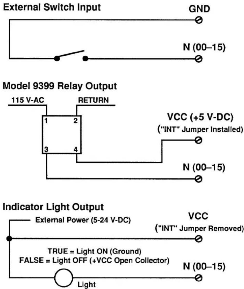
Typical logic connections are shown in Fig. 3.B.2.1(b).
Note that ALL UNUSED LOGIC INPUTS SHOULD BE "DESENSITIZED" BY TYING THEM ALL TO COMMON (GROUND). Otherwise, the logic-activity indicator lights for these lines could blink during normal operation, from pickup of stray voltages.
Fig. 3.B.2.1(a) 18-Terminal Logic I/O Connector (No. 65284.1)
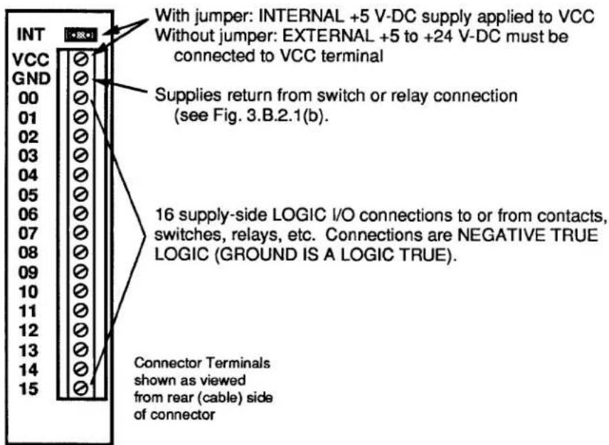
Fig. 3.B.2.1(b) Typical 10BIO-16 Logic Connections
flowchart
graph TD
A["External Switch Input"] --> B["GND"]
B --> C["N (00-15)"]
D["Model 9399 Relay Output"] --> E["115 V-AC"]
E --> F["RETURN"]
F --> G["1"]
F --> H["2"]
F --> I["3"]
F --> J["4"]
G --> K["VCC (+5 V-DC)<br>("INT" Jumper Installed)"]
H --> L["N (00-15)"]
I --> M["N (00-15)"]
N["Indicator Light Output"] --> O["External Power (5-24 V-DC)"]
O --> P["VCC<br>("INT" Jumper Removed)"]
Q["TRUE = Light ON (Ground)<br>FALSE = Light OFF (+VCC Open Collector)"] --> R["N (00-15)"]
S["Light"] --> T["Ground"]
1. 10BIO-16 INITIALIZATION: BSL COMMAND
Before you can specify which of the 10BIO-16's LOGIC I/O PORTS are to be INPUTS and which are to be OUTPUTS, you must first "initialize" the 10BIO-16 Card. You will use the B SLOT (BSL) command to establish a one-to-one correspondence between the 10BIO-16's sixteen LOGIC I/O PORTS and the sixteen members of a particular system BIT GROUP (for an explanation of BIT GROUPS and their "RANK" numbers, see Section 2.H.1).
The general form of the BSL command is
$$ \mathbf {B S L} \mathbf {s} = 1, \mathbf {k} [ \mathbf {C R} ] ^ {*} $$
The effect of this command is to assign to the Model 10BIO-16 occupying B SLOT No. "s" both a B-CARD "TYPE" code of "1" and the sixteen bits of the BIT GROUP of RANK No. "k." (All B CARDS other than the Model 10BIO-16 are automatically "typed" by the system.)
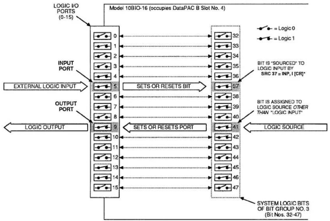
For example, to assign BIT GROUP No. 3 (i.e., Bit Nos. 32 through 47) to the LOGIC I/O PORTS of the 10BIO-16 occupying B SLOT No. 4, you would command
$$ \text { BSL } 4 = 1, 3 [ \mathrm{CR} ] ^ {*} $$
Bit No. 32 will now correspond to the 10BIO-16's LOGIC I/O PORT No. 0, Bit No. 33 to Port No. 1, Bit No. 34 to Port No. 2, etc. The situation is illustrated in Fig. 3.B.2.2. Note that in this figure the 10BIO-16's LOGIC I/O PORTS are numbered 0 through 15. These are not necessarily the numbers which appear on the 10BIO-16's LED indicator film. The card's front-edge indicator numbers will in most cases correspond to the 16 internal LOGIC BITS assigned to the card (see Section d, below).
Note also that if two or more Model 10BIO-16 Cards are present, they need not be assigned to contiguous BIT GROUPS. That is, one card might have a RANK of "1" (Bit Nos. 0-15), while a second might be ranked "4" (Bit Nos. 48-63), and a third be ranked "10" (Bit Nos. 144-159).
Fig. 3.B.2.2 Correspondence of Logic I/O Ports and System Bits
flowchart
graph TD
    A["LOGIC I/O PORTS (0-15)"] --> B["0"]
    A --> C["1"]
    A --> D["2"]
    A --> E["3"]
    A --> F["4"]
    G["INPUT PORT"] --> H["5"]
    G --> I["6"]
    G --> J["7"]
    G --> K["8"]
    L["EXTERNAL LOGIC INPUT"] --> M["5"]
    L --> N["6"]
    L --> O["7"]
    L --> P["8"]
    Q["OUTPUT PORT"] --> R["9"]
    Q --> S["10"]
    Q --> T["11"]
    Q --> U["12"]
    Q --> V["13"]
    Q --> W["14"]
    Q --> X["15"]
    Y["SETS OR RESETS BIT"] --> Z["32"]
    Y --> AA["33"]
    Y --> AB["34"]
    Y --> AC["35"]
    Y --> AD["36"]
    AE["BIT IS "SOURCED" TO LOGIC INPUT BY SRC 37 = INP, I [CR"]*] --> AF["37"]
    AG["BIT IS ASSIGNED TO LOGIC SOURCE OTHER THAN "LOGIC INPUT""] --> AH["38"]
    AG --> AI["39"]
    AG --> AJ["40"]
    AK["LOGIC OUTPUT"] --> AL["9"]
    AK --> AM["10"]
    AK --> AN["11"]
    AK --> AO["12"]
    AK --> AP["13"]
    AK --> AQ["14"]
    AK --> AR["15"]
    AS["SYSTEM LOGIC BITS OF BIT GROUP NO. 3 (Bit Nos. 32-47)"] --> AT["41"]
    AS --> AU["42"]
    AS --> AV["43"]
    AS --> AW["44"]
    AS --> AX["45"]
    AS --> AY["46"]
    AS --> AZ["47"]
3.B.2 Logic and Digital I/O
To cancel the current BIT-GROUP assignment for the 10BIO-16 occupying B SLOT No. s, command
$$ \mathbf {B S L} \mathbf {x} = 2 5 5 [ \mathbf {C R} ] ^ {*} $$
2. SPECIFYING LOGIC INPUTS: SRC COMMAND
When a given LOGIC I/O PORT is designated to be a logic input, its existing logic state will at all times directly control the state of the system LOGIC BIT that corresponds to that port—so long as no other (overriding) LOGIC SOURCE is currently in effect for that bit. See, for example, Port No. 5 in Fig. 3.B.2.2. The assignment of LOGIC SOURCES is explained in detail in Section 2.H.
To designate as a logic input the LOGIC I/O PORT corresponding to Bit No. r, thereby placing Bit No. r under direct control of any external logic signal received at that port, command
$$ \mathbf {S R C} \mathbf {r} = \text { INP }, \mathbf {I} [ \mathbf {C R} ] ^ {*} $$
where "I" is a three-letter mnemonic indicating the desired "LATCH MODE" for Bit No. r: either LAT (for latching) or NON (for nonlatching).
To designate as logic inputs the LOGIC I/O PORTS corresponding to Bit Nos. r through q, command
$$ \text { SRC } \mathbf {r} \text { TO } \mathbf {q} = \text { INP }, \text { I } [ \text { CR } ] ^ {*} $$
Returning to the example illustrated in Fig. 3.B.2.2, if a command of
$$ \text { SRC 37 } = \text { INP }, \text { NON [CR] } ^ {*} $$
has been entered, then the state of Bit No. 37 will be continuously determined by the external logic input received at LOGIC I/O PORT No. 5. If, however, the command is
$$ \text { SRC 37 } = \text { INP }, \text { LAT [CR] } ^ {*} $$
then, following the receipt of a Logic 1 at Port No. 5, Bit No. 37 will remain "latched" at Logic 1 until "unlatched" by a RELEASE (RLS) command (see Section 2.H.4)—regardless of the subsequent activity of Port No. 5.
3. SPECIFYING LOGIC OUTPUTS
When a given LOGIC I/O PORT is designated to be a logic output, its logic state (and consequently the logic level it transmits to an external device) is at any time directly controlled by the existing state of the system LOGIC BIT that corresponds to that port. See, for example, Port No. 9 in Fig. 3.B.2.2.
THERE IS NO SPECIFIC COMMAND FOR DESIGNATING A LOGIC OUTPUT. ANY LOGIC I/O PORT TO WHOSE CORRESPONDING SYSTEM LOGIC BIT A COMMAND OF
$$ \text { SRC } r = \text { INP }, I [ \text { CR } ] ^ {*} $$
HAS NOT BEEN APPLIED WILL BE AUTOMATICALLY DESIGNATED AS AN OUTPUT PORT.
Returning again to the example shown in Fig. 3.B.2.2, we see that if Bit No. 41 has been assigned any LOGIC SOURCE other than "LOGIC INPUT," then its corresponding LOGIC I/O PORT (No. 9) will produce a logic output that continuously reflects the state of Bit No. 41, regardless of the actual LOGIC SOURCE presently in control of that bit.
IMPORTANT
REMEMBER THAT ALL LOGIC OUTPUTS ARE NEGATIVE TRUE (Logic 1 = GROUND; Logic 0 = +5 V-DC). Always check connections to the logic device receiving each output, to make sure that the correct polarity is observed.
On the front edge of the Model 10BIO-16 is an LED logic-state indicator for each of the card's sixteen LOGIC I/O PORTS. This indicator will light to indicate a Logic 1 level at the respective port.
NOTE: Before a Model 10BIO-16 is shipped, a film strip is usually mounted on the indicator array, in order to number the indicators in terms of the sixteen bits of the specific system BIT GROUP associated with that card. Thus, if the 10BIO-16 LOGIC I/O PORTS are to correspond to the BIT GROUP of "RANK" No. 1, its indicators will be numbered 0 through 15; if the ports are to correspond to the BIT GROUP No. 2, the indicators will be numbered 16 through 31; etc.
PROCEDURES DISCUSSED IN THIS SECTION APPLY EQUALLY TO BOTH THE MODEL 10AIO-16 AND 10BIO-16 UNIVERSAL LOGIC I/O CARDS.
1. BINARY OUTPUT: BIN, HEX, AND CCH COMMANDS
To arrange for a Universal Logic I/O Card to output in BINARY form either a constant numerical value or the current (analog) data value of a given system DATA CHANNEL No. x, you should first
- MAKE SURE THAT THE CARD HAS BEEN PROPERLY "INITIALIZED"—THAT IS, THAT A ONE-TO-ONE CORRESPONDENCE HAS BEEN ESTABLISHED BETWEEN ITS SIXTEEN LOGIC I/O PORTS AND THE SIXTEEN MEMBERS OF A SPECIFIC SYSTEM BIT GROUP OF RANK NO. "k" (see Section c.1, above)—AND ALSO
- MAKE SURE THAT EACH OF THE CARD'S SIXTEEN LOGIC I/O PORTS HAS BEEN SPECIFIED TO BE A LOGIC OUTPUT (see Section c.3, above).
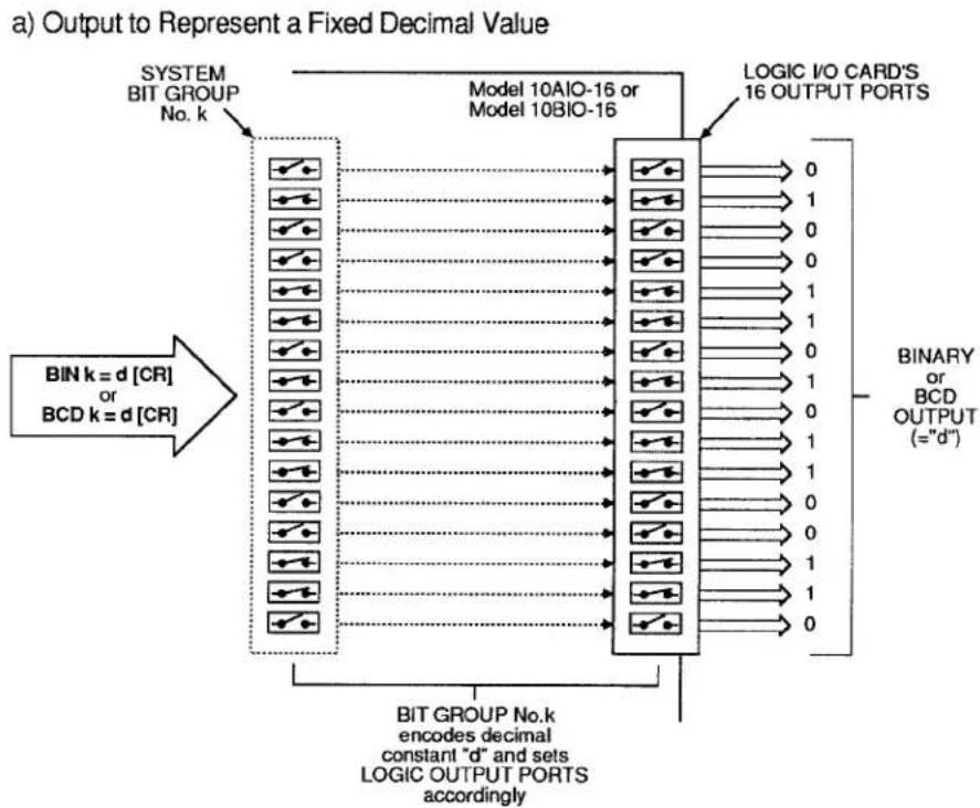
Fig. 3.B.2.3 BINARY or BCD Output from a Logic I/O Card
flowchart
graph TD
    A["BIT GROUP No.k encodes decimal constant "d" and sets LOGIC OUTPUT PORTS accordingly"] --> B["BIT k = d [CR"] or BCD k = d["CR"]]
    B --> C["Model 10AIO-16 or Model 10BIO-16"]
    C --> D["LOGIC I/O CARD'S 16 OUTPUT PORTS"]
    D --> E["Output:= "d""]
    style A fill:#f9f,stroke:#333
    style E fill:#ccf,stroke:#333
b) Output to Represent Variable Analog Data Via Analog-to-Digital Conversion Channel
flowchart
graph LR
    A["SYSTEM DATA CHANNEL No. x"] -->|ANALOG DATA| B["CONVERSION CHANNEL No. c"]
    B -->|DIGITAL DATA 0100110101100110| C["LOGIC I/O CARD'S 16 OUTPUT PORTS"]
    C --> D["BIT GROUP No. k"]
    D --> E["SET UP CONVERSION CHANNEL No. c by a command of BIN k = CHN c [CR"]* or BCD k = CHN_c["CR"]*]
    E --> F["① Set up CONVERSION CHANNEL No. c by a command of CCH c = x [CR"]*]
    F --> G["② Assign DATA CHANNEL No. x to CONVERSION CHANNEL No. c by a command of CCH c = x [CR"]*]
    G --> H["SYSTEM BIT GROUP No. k"]
    H --> I["LOGIC I/O CARD'S 16 OUTPUT PORTS"]
    I --> J["BIT GROUP No. k sets LOGIC OUTPUTS for continuous BINARY or BCD representation of DATA CHANNEL No. x."]
a. BINARY OUTPUT TO REPRESENT A FIXED DECIMAL VALUE
If you wish the Logic I/O Card dedicated to BIT GROUP No. "K" to output in BINARY form a fixed decimal value "d," you may enter a BINARY (BIN) command of the form
$$ \text { BIN } k = d [ \text { CR } ] $$
where "d" is a decimal integer from -32000 to 32000. This "RUN-TIME" COMMAND configures BIT GROUP No. "K" to represent, in BINARY form, the entered decimal value "d"—a configuration which is reflected, in turn, by the Logic I/O Card's sixteen output ports. See Fig. 3.B.2.3(a).
NOTE: Following a command of the above form, an interrogation of BIN k [CR] will yield the fixed decimal value "d" to which BIT GROUP No. k has been set.
b. BINARY OUTPUT TO REPRESENT A FIXED HEXADECIMAL VALUE
Similarly, to represent a fixed hexadecimal value "h" by the output configuration of the Logic I/O Card dedicated to BIT GROUP No. "k," you may enter a HEXADECIMAL (HEX) command of the form
$$ \text { HEX } k = h [ \text { CR } ] $$
where "h" is any four-character hexadecimal word. See Table 2.H.2, Section 2.H.2, for "Binary-Hexadecimal Equivalents." Like BINARY (BIN), the HEX command is a "RUN-TIME" COMMAND.
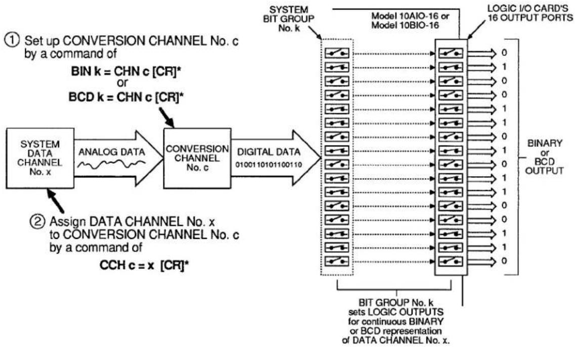
C. BINARY OUTPUT TO REPRESENT THE VALUE OF A DATA CHANNEL
If you wish the Logic I/O Card dedicated to BIT GROUP No. "k" to output in BINARY form the current analog data reading of a given system DATA CHANNEL, you should do the following (Fig. 3.B.2.3(b) summarizes the procedure):
1. SET UP CONVERSION CHANNEL FOR ANALOG-TO-DIGITAL TRANSLATION
A "CONVERSION CHANNEL" is a special system DATA CHANNEL used to mediate the translation of internal analog data into BINARY or BINARY CODED DECIMAL (BCD) output.
To set up a CONVERSION CHANNEL No. "c" for BINARY translation of internal analog data, you must first enter a BINARY (BIN) command of
$$ \text { BIN } k = \text { CHN } c [ \text { CR } ] ^ {*} $$
The number "c" can be any presently unused Channel Number in the system. This command assigns Channel No. c a "TYPE" code of B1 and causes BIT GROUP No. k to receive digitally converted data from that CONVERSION CHANNEL.
2. ESTABLISH CHANNEL NO. x AS THE "DATA SOURCE" FOR CONVERSION CHANNEL NO. c
Enter a CONVERSION CHANNEL (CCH) command of
$$ \mathbf {C C H} \mathbf {c} = \mathbf {x} [ \mathbf {C R} ] ^ {*} $$
Channel No. x may be any DATA CHANNEL ("REAL" or "PSEUDO"). This step is required in order that Channel No. x's analog data be continuously available to the system during the time taken for analog-to-digital translation.
Note that if you wish to cancel the above CCH command, you should enter a RESET (RST) command of
RST c [CR] \*
This will reset the "TYPE" code for Channel No. c to "D0" (VOLATILE DOWNLOAD PSEUDOCHANNEL). A subsequent interrogation of CCH c [CR] will receive an answer of N/A.
As illustrated in Fig. 2.B.2.3(b), the effect of the above BIN and CCH commands is to set the output configuration of the Logic I/O Card assigned to BIT GROUP No. k to represent, in BINARY form, the current value of DATA CHANNEL No. x. NOTE, HOWEVER, THAT ANY DECIMAL POINT IN THE DATA READING FOR CHANNEL NO. x WILL BE IGNORED.
ALSO NOTE: Following a BIN command of the above form, an interrogation of BIN k [CR] will not yield a decimal value corresponding to the present binary configuration of BIT GROUP k, but rather the "path of conversion" presently applying to that BIT GROUP-i.e., CHN c.
d. CANCELLING THE BIN COMMAND: BIT COMMAND
Either form of the BINARY (BIN) command has the effect of assigning to every member of BIT GROUP No. k a LOGIC SOURCE of "EXTERNAL CONTROL" (for a complete discussion of LOGIC SOURCES, see Section 2.H of this Guidebook). The BIN command will therefore override any existing LOGIC-SOURCE designation for each and every bit in the BIT GROUP.
To cancel a BINARY (BIN) command, you will have to enter a SET BIT (BIT) command that returns the 16 bits in question to their former (EEPROM-stored) LOGIC SOURCE assignments. This command will have the form
$$ \text { BIT r TO q } = \text { INT [CR] } ^ {*} $$
where "r TO q" defines the range of bits comprising the BIT GROUP to which the BIN command was applied (for "Returning to Previous Logic Source," see Section 2.H.2(c.2)).
3.B.2 Logic and Digital I/O
2. BINARY INPUT: "CHN=" AND HEX COMMANDS
To arrange for a Universal Logic I/O Card to read a BINARY input received at its LOGIC I/O PORTS, you should first
- MAKE SURE THAT THE CARD HAS BEEN PROPERLY "INITIALIZED"—THAT IS, THAT A ONE-TO-ONE CORRESPONDENCE HAS BEEN ESTABLISHED BETWEEN ITS SIXTEEN LOGIC I/O PORTS AND THE SIXTEEN MEMBERS OF A SPECIFIC SYSTEM BIT GROUP OF RANK NO. "k" (see Section c.1, above)—AND ALSO
- MAKE SURE THAT EACH OF THE CARD'S SIXTEEN LOGIC I/O PORTS HAS BEEN SPECIFIED TO BE A NONLATCHING LOGIC INPUT BY A COMMAND OF
$$ \text { SRC } \mathbf {r} \text { TO } \mathbf {q} = \text { INP }, \text { NON } [ \text { CR } ] ^ {*} $$
where "r TO q" defines the range of bits comprising BIT GROUP No. k (see Section c.2, above).
a. READING THE DECIMAL VALUE OF A BINARY INPUT
1. SET UP A "REAL" DATA CHANNEL FOR DIGITAL-TO-ANALOG TRANSLATION
To establish a "REAL" CHANNEL No. x for reading the BINARY input received by the Logic I/O Card corresponding to the system BIT GROUP of RANK No. "k," enter the following CHANNEL (CHN) command:
$$ \mathbf {C H N} \mathbf {x} = \mathbf {B I N} \mathbf {k} [ \mathbf {C R} ] ^ {*} $$
Application of this command automatically assigns to Channel No. x a "TYPE" code of B4 and a "LOCATION" designation of BIN k. It is a "SETUP" COMMAND, requiring that the EEPROM Switch be ON.
2. INTERROGATE FOR DIGITAL-INPUT CHANNEL READING
You may now use the "READ" form of the CHANNEL (CHN) command (see Section 1.H.2) to interrogate for the current reading of Channel No. x. This reading is the decimal equivalent of the BINARY value represented by the present configuration of BIT GROUP No. k-a configuration that reflects the BINARY input received by the Logic I/O Card associated with that BIT GROUP (see Fig. 3.B.2.4). Thus, depending on its mode of entry, a command of
$$ \mathrm{CHN} \times [ \mathrm{CR} ] $$
will produce either an output of this decimal value from the DataPAC's COMPUTER INTERFACE PORT or its display on the BILLBOARD; it will not return an answer of BIN k.
b. READING THE HEXADECIMAL VALUE OF A BINARY INPUT
A command of
HEX k [CR]
lets you read the hexadecimal value currently represented by the configuration of BIT GROUP No. "k"—a configuration that reflects the HEXADECIMAL value of the BINARY input received by the Logic I/O Card associated with that BIT GROUP. Depending on its mode of entry, this command will produce either an output of the appropriate four-character hexadecimal value "h" from the DataPAC's COMPUTER INTERFACE PORT or its display on the BILLBOARD (see also Section 2.H.2(c)).
Fig. 3.B.2.4 Binary or BCD Input
![Daytronic 10BHDM384 - HEX k [CR] - 1](/content/2026/05/1108709/images/00e8e4220d48015b6e6cb693043aa1227ce9bbd55b9b71f1fdcb7231dbffbddc.jpg)
flowchart
graph TD
    A["LOGIC I/O CARD'S 16 INPUT PORTS"] --> B["0"]
    A --> C["1"]
    A --> D["0"]
    A --> E["0"]
    A --> F["1"]
    A --> G["1"]
    A --> H["0"]
    A --> I["1"]
    A --> J["0"]
    A --> K["1"]
    A --> L["0"]
    A --> M["1"]
    A --> N["1"]
    A --> O["1"]
    A --> P["1"]
    A --> Q["1"]
    A --> R["1"]
    A --> S["1"]
    A --> T["1"]
    A --> U["1"]
    A --> V["1"]
    A --> W["1"]
    A --> X["1"]
    A --> Y["1"]
    A --> Z["1"]
    A --> AA["1"]
    A --> AB["1"]
    A --> AC["1"]
    A --> AD["1"]
    A --> AE["1"]
    A --> AF["1"]
    A --> AG["1"]
    A --> AH["1"]
    A --> AI["1"]
    A --> AJ["1"]
    A --> AK["1"]
    A --> AL["1"]
    A --> AM["1"]
    A --> AN["1"]
    A --> AO["1"]
    A --> AP["1"]
    A --> AQ["1"]
    A --> AR["1"]
    A --> AS["1"]
    A --> AT["1"]
    A --> AU["1"]
    A --> AV["1"]
    A --> AW["1"]
    A --> AX["1"]
    A --> AY["1"]
    A --> AZ["1"]
    A --> BA["1"]
    A --> BB["1"]
    A --> BC["1"]
    A --> BD["1"]
    A --> BE["1"]
    A --> BF["1"]
    A --> BG["1"]
    A --> BH["1"]
    A --> BI["1"]
    A --> BJ["1"]
    A --> BK["1"]
    A --> BL["1"]
    A --> BM["1"]
    A --> BN["1"]
    A --> BO["1"]
    A --> BP["1"]
    A --> BQ["1"]
    A --> BR["1"]
    A --> BS["1"]
    A --> BT["1"]
    A --> BU["1"]
    A --> BV["1"]
    A --> BW["1"]
    A --> BX["1"]
    A --> BY["1"]
    A --> BZ["1"]
    A --> CA["1"]
    A --> CB["1"]
    A --> CC["1"]
    A --> CD["1"]
    A --> CE["1"]
    A --> CF["1"]
    A --> CG["1"]
    A --> CH["1"]
    A --> CI["1"]
    A --> CJ["1"]
    A --> CK["1"]
    A --> CL["1"]
    A --> CM["1"]
    A --> CN["1"]
    A --> CO["1"]
    A --> CP["1"]
    A --> CQ["1"]
    A --> CR["1"]
    A --> CS["1"]
    A --> CT["1"]
    A --> CU["1"]
    A --> CV["1"]
    A --> CW["1"]
    A --> CX["1"]
    A --> CY["1"]
    A --> CZ["1"]
    A --> DA["1"]
    A --> DB["1"]
    A --> DC["1"]
    A --> DV["1"]
    A --> DW["1"]
    A --> DX["1"]
    A --> DXB["1"]
    B --> DB
    B --> CX
    B --> CY
    B --> CZ
    B --> CX
    B --> CY
    B --> CXB
    B --> CYB
    B --> CX
    B --> CY
    B --> CXB
    B --> CYB
    B --> CX
    B --> CY
3. BCD OUTPUT: BCD AND CCH COMMANDS
See the procedures for the setting up of fixed and variable BINARY output, Sections e.1(a) and e.1(c), above. The procedures for the setting up of output in BCD form from a Universal Logic I/O Card is strictly analogous, except that here you will use the BINARY CODED DECIMAL (BCD) command instead of the BINARY (BIN) command.
a. BCD OUTPUT TO REPRESENT A FIXED DECIMAL VALUE
Here you will enter a command of
$$ \mathbf {B C D} \mathbf {k} = \mathbf {d} [ \mathbf {C R} ] $$
where the entered decimal value "d" is an integer from -7999 to 7999.
b. BCD OUTPUT TO REPRESENT THE VALUE OF A DATA CHANNEL
1. SET UP CONVERSION CHANNEL FOR ANALOG-TO-DIGITAL TRANSLATION
To set up a CONVERSION CHANNEL No. "c" for BCD translation of internal analog data, you must enter a BINARY CODED DECIMAL (BCD) command of
$$ \mathbf {B C D} \mathbf {k} = \mathbf {C H N} \mathbf {c} [ \mathbf {C R} ] ^ {*} $$
The command assigns Channel No. c a "TYPE" code of B2 and causes BIT GROUP No. k to receive digitally converted data from that CONVERSION CHANNEL.
2. ESTABLISH DATA CHANNEL NO. x AS THE "DATA SOURCE" FOR CONVERSION CHANNEL NO. c
3.B.2 Logic and Digital I/O
As with BINARY output (Section e.1), you will enter a CONVERSION CHANNEL (CCH) command of
$$ \mathbf {C C H} \mathbf {c} = \mathbf {x} [ \mathbf {C R} ] ^ {*} $$
Again as with BINARY output, ANY DECIMAL POINT IN THE DATA READING FOR CHANNEL NO. x WILL BE IGNORED.
C. CANCELLING THE BCD COMMAND: BIT COMMAND
You will use a SET BIT (BIT) command of
$$ \text { BIT } \mathbf {r} \text { TO } \mathbf {q} = \text { INT } [ \mathbf {C R} ] ^ {*} $$
as explained in Section e.1(d), above.
4. BCD INPUT: "CHN=" COMMAND
See the procedure for the reading of BINARY input, Section e.2(a), above. The procedure for the reading of a BCD input received by a Universal Logic I/O Card is strictly analogous.
a. SET UP A "REAL" DATA CHANNEL FOR DIGITAL-TO-ANALOG TRANSLATION
To establish a "REAL" CHANNEL No. x for reading the BCD input received by the Logic I/O Card corresponding to the system BIT GROUP of RANK No. "k," command
$$ \mathbf {C H N} \mathbf {x} = \mathbf {B C D} \mathbf {k} [ \mathbf {C R} ] ^ {*} $$
Application of this "SETUP" COMMAND automatically assigns to Channel No. x a "TYPE" code of B3 and a "LOCATION" designation of BCD k.
b. INTERROGATE FOR DIGITAL-INPUT CHANNEL READING
As with BINARY input (Section e.2(a)), you may use a command of
$$ \mathbf {C H N} \times [ \mathbf {C R} ] $$
to interrogate for the decimal equivalent of the BCD value represented by the present configuration of BIT GROUP No. k-a configuration that reflects the BCD input received by the Logic I/O Card associated with that BIT GROUP (see again Fig. 3.B.2.4). Note that the above interrogation will not return an answer of BCD k.
Section 3.B.3
Satellite Network Systems:
Model 10BD4
Satellite Interface Card and
Model 10BD1
Satellite Slave Card

DAYTRONIC
System 10 Guidebook
The Ground Truth image displays a single, solid horizontal line, which is a stylistic or background element (like a ruled paper line or separator), not a placeholder for text. According to Rule 2, such stylistic/background lines must be ignored by the OCR result. The OCR content provided is "", which consists of no characters. This correctly represents the line in the GT by ignoring it entirely. Since the OCR output includes no underscores for this line, this complies with the “Stylistic/Background Lines (Ignore)” rule. Therefore, the OCR result is consistent with the Ground Truth.
1. THE SATELLITE NETWORK
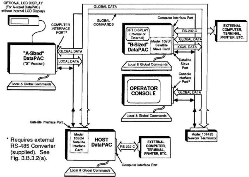
When equipped with an optional Model 10BD4 Satellite Interface Card, any "B-sized" DataPAC can become a central "master" or "HOST" unit for a Local Area Network consisting of one or more Daytronic "SATELLITE" units. Any "B-sized" DataPAC may function as a SATELLITE (Model 10K6, 10K7, 10K8, etc.). An "A-sized" DataPAC may function as a SATELLITE only if it is a special "S" version of that DataPAC model (i.e., Model 10KUS, 10K1S, 10K2S, 10K4S, 10K4DS, etc.). A Model 10CON or 10CCON Operator Console can also serve as a SATELLITE unit. All in all, such SATELLITES can provide complete remote-site data acquisition, data display, process control, or entry of "GLOBAL" system commands.
While responding instantly and "transparently" to interrogation by the HOST DataPAC, each SATELLITE DataPAC remains independently responsible for all data collection, control, and/or display functions relating to those DATA CHANNELS and LOGIC BITS for which it serves as a unique "local" origin. These functions may include cross-channel calculations, analog peak capture, logic and analog control I/O, automatic command "executes," maintenance of "live" LCD or CRT display, digital "history" recording, etc.
Fig. 3.B.3.1 shows a generalized SATELLITE system. Specific connections are described in Section b.3, below. HOST-SATELLITE and SATELLITE-SATELLITE interchanges are achieved via RS-485 serial interface of fixed protocol, which allows up to 31 SATELLITES on a twisted-pair ring of up to 1 km (3279 ft.) in total length. Note, however, that optional provisions are available for handling up to 99 SATELLITES in all.
Fig. 3.B.3.1 Generalized Satellite Network
flowchart
graph TD
    A[""A-Sized" DataPAC ("S" Version)"] -->|GLOBAL DATA| B["HOST DataPAC"]
    B -->|Model 10BD4 Satellite Interface Card| C["Local & Global Commands"]
    B -->|RS-232-C| D["External Computer, Terminal, Printer, ETC."]
    B -->|Computer Interface Port| E["Model 10T485 Network Terminator"]
    B -->|Satellite Interface Port| F["OPERATOR CONSOLE"]
    F -->|Model 10BD1 Satellite Slave Card| G["Model 10B1 Satellite"]
    G -->|RS-232-C| H["External Computer, Terminal, Printer, ETC."]
    G -->|Global Data| I["External Computer, Terminal, Printer, ETC."]
    J["OPTIONAL LCD DISPLAY (For A-sized DataPACs without internal LCD Display)"] --> A
    K["COMPUTER INTERFACE PORT*"] --> A
    L["LOCAL DATA"] --> B
    M["GLOBAL DATA"] --> B
    N["GLOBAL COMMANDS"] --> B
    O["RS-232-C"] --> P["EXTERNAL COMPUTER, TERMINAL, PRINTER, ETC."]
    Q["GLOBAL DATA"] --> R["EXTERNAL COMPUTER, TERMINAL, PRINTER, ETC."]
    S["Model 10BD1 Satellite Slave Card"] --> T["Model 10BD1 Satellite Slave Card"]
    U["Model 10BD1 Satellite Slave Card"] --> V["Model 10BD1 Satellite Slave Card"]
    W["Model 10BD1 Satellite Slave Card"] --> X["Model 10BD1 Satellite Slave Card"]
    Y["Model 10BD1 Satellite Slave Card"] --> Z["Model 10BD1 Satellite Slave Card"]
    AA["Model 10BD1 Satellite Slave Card"] --> AB["Model 10BD1 Satellite Slave Card"]
    AC["Model 10BD1 Satellite Slave Card"] --> AD["Model 10BD1 Satellite Slave Card"]
    AE["Model 10BD1 Satellite Slave Card"] --> AF["Model 10BD1 Satellite Slave Card"]
    AG["Model 10BD1 Satellite Slave Card"] --> AH["Model 10BD1 Satellite Slave Card"]
    AI["External Computer Interface Port"] --> AJ["External Computer, TERMINAL, PRINTER, ETC."]
    AK["External Computer Interface Port"] --> AL["External Computer, TERMINAL, PRINTER, ETC."]
    AM["External Computer Interface Port"] --> AN["External Computer, TERMINAL, PRINTER, ETC."]
    AO["External Computer Interface Port"] --> AP["External Computer, TERMINAL, PRINTER, ETC."]
    AQ["External Computer Interface Port"] --> AR["External Computer, TERMINAL, PRINTER, ETC."]
    AS["External Computer Interface Port"] --> AT["External Computer, TERMINAL, PRINTER, ETC."]
    AU["External Computer Interface Port"] --> AV["External Computer, TERMINAL, PRINTER, ETC."]
    AW["External Computer Interface Port"] --> AX["External Computer, TERMINAL, PRINTER, ETC."]
    AY["Satellite Interface Port"] --> BZ["Satellite Interface Port"]
    AZ["* Requires external RS-485 Converter (supplied). See Fig. 3.B.3.2(a)."] --> BA["Satellite Interface Port"]
The Daytronic SATELLITE NETWORK is a form of "packet network." This means that it provides for the sequential delivery of discrete "data packets" from each SATELLITE to the HOST and from each SATELLITE (or HOST) to every "B-sized" SATELLITE in the network. It also provides for the sequential delivery of discrete "message packets" from each SATELLITE to the HOST. Each message packet contains any standard MNEMONIC COMMANDS that have been entered at the SATELLITE location, but which are intended for delivery to some other member or members of the network.
In setting up the network, you will first assign a unique identifying SATELLITE NUMBER to each SATELLITE. You may then dedicate to the HOST DataPAC and to each DataPAC SATELLITE in the network a selected range of "GLOBAL" DATA CHANNELS and a selected range of "GLOBAL" BIT GROUPS ("global" here means that such a DATA CHANNEL or BIT GROUP may be read and/or displayed, if desired, by any member of the SATELLITE NETWORK).
Each DataPAC will now serve as the unique "data origin" for its specified channels and bits. The dedication of "GLOBAL" channels and bits to network DataPACs is done via the SATELLITE (SAT) and SATELLITE SYSTEM BITS (SSB) commands, respectively. GLOBAL DATA CHANNEL No. 1 must always be dedicated to the HOST.
PLEASE NOTE
In the "simplified" setup procedures discussed in this section, it is convenient to consider all active DATA CHANNELS and all active LOGIC BITS to be "GLOBAL," regardless of whether they originate from a SATELLITE DataPAC or from the HOST. Concerning "GLOBAL" data, you should note that
- "GLOBAL" CHANNELS AND BITS ARE SIMULTANEOUSLY AVAILABLE TO THE HOST AND TO EVERY SATELLITE IN THE NETWORK.
- As explained in Sections b.5(b) and b.6(a), below, EACH "GLOBAL" CHANNEL OR BIT MAY BE DEDICATED TO ANY DATAPAC IN THE NETWORK (HOST OR SATELLITE)-BUT ONLY TO THAT SINGLE DATAPAC. IT MAY BE "READ" (OR "HEARD"), HOWEVER, BY EVERY OTHER NETWORK MEMBER (see Sections b.5(c,d) and b.6(b,c).
After the network has been fully set up, the Model 10BD4 will automatically interrogate each SATELLITE in turn, according to the predesignated SATELLITE-NUMBER sequence, having first interrogated the HOST DataPAC. The 10BD4 operates on a scan cycle which is independent of that of the HOST'S CENTRAL PROCESSOR.
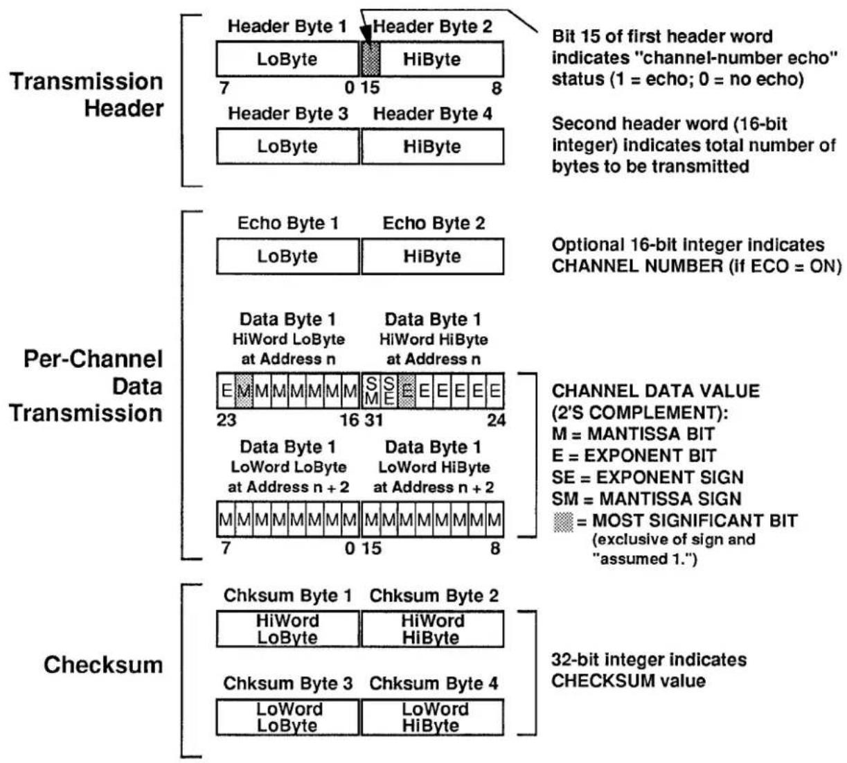
When interrogated, each network DataPAC (HOST or SATELLITE) will transmit a "data packet" to the Model 10BD4. That is, it will send to the 10BD4, in sequence, the numeric data values and logic states currently in its DATA RAM for all GLOBAL DATA CHANNELS and GLOBAL BIT GROUPS that have been specifically dedicated to that DataPAC. Following each data packet, the interrogated DataPAC will also transmit a "CHECKSUM" number. This is simply the numeric summation of the data that has just been transmitted. The 10BD4 will perform a similar summation for each data packet it receives, and will compare its own "CHECKSUM" with that reported by the transmitting DataPAC. This procedure allows detection of faulty data transfer from SATELLITE (or HOST) to the Model 10BD4 (for the monitoring of transmission errors, see Section c.6, below).
With each of its own scan cycles, the HOST DataPAC's CENTRAL PROCESSOR interrogates the Model 10BD4 for all current data in the 10BD4's DATA RAM, as collected from all DataPAC SATELLITES in the network. The HOST then updates its own DATA RAM accordingly, publishing all network-collected data to any and all of its "COPROCESSOR" CARDS (i.e., to every Model 10BDR64 History Card, Model 10BACI Auxiliary Computer Interface Card, etc., contained in the HOST DataPAC).
At the same time that it is transmitted to the Satellite Interface Card, a given data packet is transmitted to every "B-sized" SATELLITE in the network. This same data is further available to every "A-sized" satellite that has been configured to receive it, through the HOST. After receiving data from another SATELLITE or from the HOST, a SATELLITE will accordingly update the corresponding DATA CHANNELS and LOGIC BITS in its own DATA RAM, and also any "local" LCD or CRT display of any of these channels and bits for which it is responsible.
The network also allows any SATELLITE to issue commands to any other SATELLITE or to the HOST. Every interrogation by the 10BD4 for SATELLITE data will be accompanied by an interrogation for a "message packet"-i.e., for any MNEMONIC COMMANDS that may be currently awaiting delivery from the SATELLITE in question to some other member of the network. On receipt by the 10BD4, all such "GLOBAL" COMMANDS are immediately sent to the HOST'S CENTRAL PROCESSOR. From there each command is routed directly to the individual network unit to which it is "implicitly" addressed by virtue of the GLOBAL DATA CHANNEL(S) or GLOBAL LOGIC BIT(S) referred to by the command itself, or to which it has been "explicitly" addressed by means of an OPEN (OPN) or NODE (NOD) command (see Sections c.1 and c.5, below). Because of this GLOBAL COMMAND capability, the total system can accommodate more than one observation station throughout the network.
In contrast to a "GLOBAL" COMMAND, which may be entered through the keyboard, COMPUTER INTERFACE PORT, or optional AUXILIARY COMPUTER INTERFACE (ACI) PORT of any member of the network in order to be sent to any other member, a "LOCAL" COMMAND can only be "heard" and acted upon by the unit whose keyboard, COMPUTER INTERFACE PORT, or ACI PORT has been used to enter that command.
When interrogated by the 10BD4, each OPERATOR CONSOLE SATELLITE will only transmit its current message packet (these units do not transmit data; they only receive it for purposes of "local" display, printout, recording, etc.). GLOBAL COMMANDS MAY BE RECEIVED OR ISSUED BY AN OPERATOR CONSOLE SATELLITE ONLY THROUGH THE OPEN (OPN) COMMAND.
2. TYPES OF SATELLITES
a. "A-SIZED" DATAPAC ("S" VERSION)
TO INTERACT PROPERLY WITH THE SATELLITE NETWORK, AN "A-SIZED" DATAPAC SATELLITE MUST BE A SPECIAL "S" VERSION OF THAT DATAPAC MODEL.* All "S"-version DataPACs have limited bidirectionality. They are also provided with a capacity of 1000 DATA CHANNELS and with a PLUG-IN KEYBOARD CONNECTOR, thereby permitting the direct keyboard entry of MNEMONIC COMMANDS, both "LOCAL" and "GLOBAL." Such a SATELLITE cannot receive "LOCAL" COMMANDS through its COMPUTER INTERFACE PORT, which is necessarily dedicated to the network (see Fig. 3.B.3.1).
Note that with certain "A-sized" DataPAC SATELLITES, the immediate review and verification of keyboard command entries is not possible, because an internal LCD display is not present. "A-sized" SATELLITES without LCD display include the Models 10KUS, 10K1S, and 10K4TS. It is therefore recommended that any system employing such a SATELLITE also include a Model 10LCD12A Display Option, which provides a remote 12-line LCD display and a Model 10P80A Extended Keyboard.
b. "B-SIZED" DATAPAC WITH MODEL 10BD1 SATELLITE SLAVE
Every "B-sized" DataPAC SATELLITE must have a capacity of 1000 DATA CHANNELS. It also requires a Model 10BD1 Satellite Slave Card in order to issue its own locally acquired data to the network and to receive GLOBAL DATA from the network for local display, printout, etc. Such a SATELLITE can receive commands "locally" through its plug-in keyboard, through its COMPUTER INTERFACE PORT (which in this case is not dedicated to the network), or through the AUXILIARY COMPUTER INTERFACE PORT supplied by an optional Model 10BACI (see Section 3.B.5 of this Guidebook).
C. OPERATOR CONSOLE (MODEL 10CON OR 10CCON)
An OPERATOR CONSOLE can only receive GLOBAL DATA from the network.
However, it can both issue and receive GLOBAL COMMANDS via the OPEN (OPN) command, just like an "A-sized" or "B-sized" DataPAC SATELLITE. Like an "A-sized" DataPAC SATELLITE, it can receive LOCAL COMMANDS through its plug-in keyboard (only). For more information on the Models 10CON and 10CCON, see Section 2.O of the Guidebook.
3. SYNOPSIS OF SATELLITE SETUP PROCEDURE
In general, the setup of a System 10 SATELLITE NETWORK will involve the following steps, in the order given. Each step is discussed in detail in the sections that follow.
PLEASE NOTE
In order that you may set up your SATELLITE NETWORK as quickly and easily as possible, the following procedure is offered as the simplest and most straightforward method. You should know, however, that more complicated setup techniques are possible, some of which may, under certain circumstances, increase overall system speed.
- Make sure that each "A-sized" DataPAC SATELLITE in the system is set for a COMMAND TERMINATOR of CARRIAGE RETURN [CR].
- Make sure that the HOST DataPAC has been assigned a SATELLITE NUMBER of "0" (zero), via an ASSIGN SATELLITE NUMBER (ASN) command applied to the HOST.
- Assign a unique nonzero SATELLITE NUMBER to each SATELLITE in the network, via an ASN command applied to the SATELLITE.
- Establish proper CABLE CONNECTIONS between adjacent SATELLITES and between the "first" SATELLITE and the HOST DataPAC's SATELLITE INTERFACE PORT.
- Make sure that the following RS-232-C protocol is observed by every "A-sized" DataPAC SATELLITE at its COMPUTER INTERFACE PORT, by setting the DataPAC's Protocol Switches accordingly:
153.6K BAUD, 8 DATA BITS, 2 STOP BITS, ODD PARITY
-
Set the HOST DataPAC's TERMINATOR CHANNEL, via the TERMINATOR (TER) command, so that the HOST will scan all active GLOBAL DATA CHANNELS.
-
Use the TERMINATOR (TER) or SCAN (SCN) command to set for each DataPAC SATELLITE a SCAN RANGE that contains all channels to be "heard" by that SATELLITE; this includes all channels to be dedicated to the SATELLITE in Step 8.
-
Apply a SATELLITE (SAT) command to the HOST DataPAC for each DataPAC SATELLITE that is to serve as the "data origin" for one or a range of GLOBAL DATA CHANNELS.
-
If you wish an "A-sized" DataPAC SATELLITE to be able to read and/or display one or more GLOBAL DATA CHANNELS which have not been dedicated to that SATELLITE in Step 8, first apply a DOWNLOAD CHANNELS (DLC) command to the HOST DataPAC, specifying the GLOBAL DATA CHANNEL(S) to be downloaded to every "A-sized" DataPAC SATELLITE in the network with each 10BD4 scan cycle.
-
Then apply one or more TYPE (TYP) commands to the "A-sized" DataPAC in question, to assign a local "TYPE" code of "D4" to each 10BD4-downloaded channel the DataPAC is to read and/or display.
3.B.3 Satellite Network Systems
- If you wish a "B-sized" DataPAC SATELLITE to be able to read and/or display one or more GLOBAL DATA CHANNELS which have not been dedicated to that SATELLITE in Step 8, apply the special "B-SLOT" form of the LOCATE (LCT) command to that DataPAC to locally "locate" each such channel to the SATELLITE'S 10BD1 card.
- Apply a SATELLITE SYSTEM BITS (SSB) command to the HOST DataPAC for each DataPAC SATELLITE that is to serve as the "data origin" for one or a range of GLOBAL BIT GROUPS.
- If you wish an "A-sized" DataPAC SATELLITE to be able to read one or more GLOBAL LOGIC BITS which have not been dedicated to that SATELLITE in Step 12, first apply a DOWNLOAD BITS (DLB) command to the HOST DataPAC, specifying the GLOBAL BIT GROUP(S) to be downloaded to every "A-sized" DataPAC SATELLITE in the network with each 10BD4 scan cycle.
- Then apply one or more LOGIC SOURCE (SRC) commands to the "A-sized" DataPAC in question, to assign a local LOGIC SOURCE of "SAT" to each 10BD4-downloaded bit the DataPAC is to read.
- If you wish a "B-sized" DataPAC SATELLITE to be able to read and/or display one or more GLOBAL LOGIC BITS which have not been dedicated to that SATELLITE in Step 12, apply the special "B-SLOT" form of the LOGIC SOURCE (SRC) command to that DataPAC to locally "source" each such bit to the SATELLITE'S 10BD1 card.
- Using the standard procedures given in Sections 1 and 2 of this Guidebook, set up the DATA CHANNELS of each DataPAC SATELLITE that are to be used for the "local" acquisition of numeric data—i.e., that have been specifically dedicated to that SATELLITE via a SATELLITE (SAT) command applied to the HOST (Step 8). Also set up all HOST channels that are to be so used.
- Again using standard procedures, set up the BIT GROUPS of each DataPAC SATELLITE that have been specifically dedicated to that SATELLITE via a SATELLITE SYSTEM BITS (SSB) command applied to the HOST (Step 12). Also set up all HOST BIT GROUPS that are to be so used.
- Apply a command of SAT n = CON [CR]* to the HOST DataPAC for each OPERATOR CONSOLE SATELLITE (No. "n") in the network.
- Perform all necessary VIDEO SETUP for each SATELLITE with LCD or CRT "video capability," and also for the HOST DataPAC.
- Use the EXECUTE BASE GROUP (XBG) command to set appropriate EXECUTE BASE GROUPS for any SATELLITES to be loaded with EXECUTE (EXU) statements.
For "Considerations for Altering an Existing Satellite Network," see the Appendix at the end of this Guidebook section.
4. SATELLITE CARD STATUS INDICATORS
The Satellite Card has nine front-panel STATUS INDICATORS. The top four lights are red, to indicate "ERROR" or "ALERT" conditions. The remaining lights are green.
DTR
When this light is ON, it means that the 10BD4 is not asserting DATA TERMINAL READY. The 10BD4 input buffer is full, and it is therefore NOT READY TO RECEIVE DATA from the network.
RTS
When this light is ON, it means that the 10BD4 is prevented from transmitting to the SATELLITE network because one or more SATELLITES are not asserting "DATA TERMINAL READY."
TMOE
When this light is ON, it means that a TIMEOUT ERROR has been detected—that is, that a SATELLITE is not answering an interrogation by the 10BD4. For the "logging" of TIMEOUT ERRORS, see the SATELLITE ERROR LOG (SEL) command, Section c.6(a), below. "TMOE" indication is not exercised on the Model 10BD1 Satellite Slave Card.
CSUM
When this light is ON, it indicates a CHECKSUM ERROR with respect to a SATELLITE'S data transmission to the 10BD4. Again, see the SEL command, Section c.6(a). "CSUM" indication is not exercised on the Model 10BD1 Satellite Slave Card.
CHR
When this light is ON, it means that the 10BD4 has received a valid ASCII CHARACTER.
MNE
When this light is ON, it means that the HOST DataPAC has received through its COMPUTER INTERFACE PORT a valid MNEMONIC COMMAND relating to the Satellite Interface Card.
RET
When this light is ON, it means that the last character received by the 10BD4 was a CARRIAGE RETURN ([CR]).
XMT
When this light is ON, it means that there is presently some activity on the 10BD4's data-transmission line.
RCV
When this light is ON, it means that there is presently some activity on the 10BD4's data-reception line.
3.B.3 Satellite Network Systems
1. SETTING COMMAND TERMINATOR FOR "A-SIZED" DATAPAC SATELLITES: CMT COMMAND
Every "A-sized" DataPAC SATELLITE must be set to recognize a "standard" COMMAND TERMINATOR of CARRIAGE RETURN ([CR]).
Note that the HOST DataPAC, all "B-SIZED" DataPAC SATELLITES, and all OPERATOR CONSOLE SATELLITES are preset to recognize this COMMAND TERMINATOR at the respective ports through which they interface with the network. FOR EACH SUCH UNIT, THE COMPUTER INTERFACE PORT NEED NOT BE SET TO RECOGNIZE A COMMAND TERMINATOR OF [CR].
Unless otherwise specified, every "A-sized" DataPAC will have been factory-set, prior to shipment, to recognize a "standard" command termination of [CR]. If for some reason a different COMMAND TERMINATOR has been previously designated for the DataPAC, then it will have to be reset by turning ON the DataPAC's EEPROM Write Protect Switch and entering a command of the form
$$ \mathbf {C M T} = [ \mathbf {0 D} ] [ \mathbf {C R} ] ^ {*} $$
via the DataPAC's keyboard. For full details on the COMMAND TERMINATOR (CMT) command, see Section 2.B.5 of this Guidebook.
2. ASSIGNING SATELLITE NUMBERS: ASN COMMAND
a. ASSIGNING SATELLITE NUMBER TO THE HOST
IN ORDER FOR IT TO OPERATE AS THE NETWORK "MASTER" UNIT, THE HOST DATAPAC MUST BE ASSIGNED A "SATELLITE NUMBER" OF "0" (ZERO). Note that all DataPACs are factory-set, prior to shipment, to this SATELLITE NUMBER.
To make sure, however, that your HOST is properly set, turn ON its EEPROM Write Protect Switch and enter the following ASSIGN SATELLITE NUMBER (ASN) command, via the HOST'S plug-in keyboard:
$$ \mathbf {A S N} = \mathbf {0} [ \mathbf {C R} ] ^ {*} $$
The effect of this command is to place the HOST DataPAC's CENTRAL PROCESSOR in the "master" mode.
b. ASSIGNING SATELLITE NUMBERS TO SATELLITES
EVERY SATELLITE IN THE SYSTEM MUST BE ASSIGNED A UNIQUE, NONZERO "SATELLITE NUMBER." Without this identifying number, no data or command interchanges can take place between the HOST and the SATELLITE or between the SATELLITE and other SATELLITES.
NOTE
IT IS RECOMMENDED THAT, IF POSSIBLE, YOU ASSIGN TO EACH SATELLITE ITS RESPECTIVE SATELLITE NUMBER BEFORE CONNECTING THAT SATELLITE TO THE NETWORK.
The following ASSIGN SATELLITE NUMBER (ASN) command should be issued directly to each SATELLITE via that SATELLITE'S own keyboard, after the SATELLITE'S EEPROM Write Protect Switch has been turned ON:
$$ \mathbf {A S N} = \mathbf {n} [ \mathbf {C R} ] ^ {*} $$
where "n" is the unique SATELLITE NUMBER whereby the given SATELLITE (alone) is to be identified (1 ≤ n ≤ 99).
The effect of this command is to place the SATELLITE'S CENTRAL PROCESSOR in the "slave" mode and to give it a unique "address" within the network.*
3. NETWORK INTERCONNECTIONS
Consisting of three shielded twisted pairs wired pin-to-pin between identical 9-pin connectors, the network's "RS-485" linkage allows the daisy-chaining of SATELLITES in a ring of up to 1 km (3279 ft.) in total length. A single Model 10BD4 Satellite Interface Card can normally accommodate up to 31 SATELLITES, although optional provisions permit the linkage of up to 99 SATELLITE units to a single HOST DataPAC (contact the factory for details).
The 10BD4's SATELLITE INTERFACE PORT furnishes two separate 9-pin RS-485 SATELLITE INTERFACE CONNECTORS. For convenience, you may use either or both of these connectors in constructing your network, depending on the physical placement of the HOST with respect to other network members.
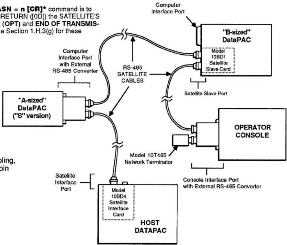
Fig. 3.B.3.2(a) shows a ring of three SATELLITES, corresponding to the three basic types of SATELLITES discussed in Section a.2, above. In this case, only one of the 10BD4's 9-pin SATELLITE INTERFACE CONNECTORS is used.
In Fig. 3.B.3.2(b), both of the 10BD4's 9-pin connectors are used, since the HOST is situated midway between the extreme members of the network. NOTE THAT ALTHOUGH TWO SEPARATE SATELLITE CHAINS ARE HERE SHOWN, EACH WITH ITS OWN NETWORK TERMINATOR, THERE IS STILL ONLY ONE BASIC SATELLITE NETWORK.
* Another important effect of the ASN = n [CR]* command is to automatically set to CARRIAGE RETURN ([OD]) the SATELLITE'S current OUTPUT TERMINATOR (OPT) and END OF TRANSMISSION TERMINATOR (EOT)—see Section 1.H.3(g) for these parameters.
flowchart
graph TD
    A["HOST DATAPAC"] --> B[""A-sized" DataPAC ("S" version)"]
    B --> C["Computer Interface Port with External RS-485 Converter"]
    C --> D["RS-485 SATELLITE CABLES"]
    D --> E["Model 10BD1 Satellite Slave Card"]
    E --> F[""B-sized" DataPAC"]
    F --> G["Satellite Slave Port"]
    G --> H["OPERATOR CONSOLE"]
    H --> I["Console Interface Port with External RS-485 Converter"]
    I --> J["Model 10T485 Network Terminator"]
    J --> K["Satellite Interface Port"]
    K --> L["Computer Interface Port"]
    L --> M["B-sized" DataPAC"]
    M --> N["Model 10BD1 Satellite Slave Card"]
    N --> O["Satellite Slave Port"]
    O --> P["Operator CONSOLE"]
    P --> Q["Console Interface Port with External RS-485 Converter"]
    Q --> R["Model 10BD4 Satellite Interface Card"]
    R --> S["Satellite Interface Port"]
Fig. 3.B.3.2(a) Satellite Network Cabling, Using One 10BD4 9-pin Interface Connector
3.B.3 Satellite Network Systems

flowchart
graph TD
    A["Satellite Interface Port"] --> B["Model 10BD4 Satellite Interface Card"]
    B --> C["Model 10T485 Network Terminator"]
    C --> D["Host DATAPAC"]
    D --> E["Satellite Interface Port"]
    E --> F["Satellite Interface Port"]
    F --> G["Model 10BD4 Satellite Interface Card"]
    G --> H["Satellite Interface Port"]
    H --> I["Satellite Interface Port"]
    I --> J["Satellite Interface Port"]
    J --> K["Satellite Interface Port"]
    K --> L["Satellite Interface Port"]
    L --> M["Satellite Interface Port"]
    M --> N["Satellite Interface Port"]
    N --> O["Satellite Interface Port"]
    O --> P["Satellite Interface Port"]
    P --> Q["Satellite Interface Port"]
    Q --> R["Satellite Interface Port"]
    R --> S["Satellite Interface Port"]
    S --> T["Satellite Interface Port"]
    T --> U["Satellite Interface Port"]
    U --> V["Satellite Interface Port"]
    V --> W["Satellite Interface Port"]
    W --> X["Satellite Interface Port"]
    X --> Y["Satellite Interface Port"]
    Y --> Z["Satellite Interface Port"]
    Z --> AA["Satellite Interface Port"]
    AA --> AB["Satellite Interface Port"]
    AB --> AC["Satellite Interface Port"]
    AC --> AD["Satellite Interface Port"]
    AD --> AE["Satellite Interface Port"]
    AE --> AF["Satellite Interface Port"]
    AF --> AG["Satellite Interface Port"]
    AG --> AH["Satellite Interface Port"]
    AH --> AI["Satellite Interface Port"]
    AI --> AJ["Satellite Interface Port"]
    AJ --> AK["Satellite Interface Port"]
    AK --> AL["Satellite Interface Port"]
    AL --> AM["Satellite Interface Port"]
    AM --> AN["Satellite Interface Port"]
    AN --> AO["Satellite Interface Port"]
    AO --> AP["Satellite Interface Port"]
    AP --> AQ["Satellite Interface Port"]
    AQ --> AR["Satellite Interface Port"]
    AR --> AS["Satellite Interface Port"]
    AS --> AT["Satellite Interface Port"]
    AT --> AU["Satellite Interface Port"]
    AU --> AV["Satellite Interface Port"]
    AV --> AW["Satellite Interface Port"]
    AW --> AX["Satellite Interface Port"]
    AX --> AY["Satellite Interface Port"]
    AY --> AZ["Satellite Interface Port"]
    AZ --> BA["Satellite Interface Port"]
    BA --> BB["Satellite Interface Port"]
    BB --> BC["Satellite Interface Port"]
    BC --> BD["Satellite Interface Port"]
    BD --> BE["Satellite Interface Port"]
    BE --> BF["Satellite Interface Port"]
    BF --> BG["Satellite Interface Port"]
    BG --> BH["Satellite Interface Port"]
    BH --> BI["Satellite Interface Port"]
    BI --> BJ["Satellite Interface Port"]
    BJ --> BK["Satellite Interface Port"]
    BK --> BL["Satellite Interface Port"]
    BL --> BM["Satellite Interface Port"]
    BM --> BN["Satellite Interface Port"]
    BN --> BO["Satellite Interface Port"]
    BO --> BP["Satellite Interface Port"]
    BP --> BQ["Satellite Interface Port"]
A sufficient number of RS-485 SATELLITE CABLES are supplied with every ordered SATELLITE NETWORK system. These cables establish all network data and command interchanges by connecting consecutive network members in daisy-chain fashion. Each individual SATELLITE CABLE may be of indefinite length, so long as the total length of the SATELLITE ring does not exceed 1 km (3279 ft.).
As shown in Fig. 3.B.3.2(a), an external RS-485 converter connector is mounted on the rear panel of every "A-sized" DataPAC SATELLITE. This is required to convert the standard RS-232-C line configuration of the DataPAC's COMPUTER INTERFACE PORT to the pin-to-pin RS-485 configuration shown in Fig. 3.B.3.3. Attaching directly to the DataPAC's 25-pin COMPUTER INTERFACE CONNECTOR, the converter furnishes two 9-pin RS-485 connectors for connection either of two SATELLITE CABLES or of one SATELLITE CABLE and one NETWORK TERMINATOR.
For a "B-sized" DataPAC SATELLITE, a Model 10BD1 Satellite Slave Card is always used in place of the DataPAC's COMPUTER INTERFACE PORT to link the DataPAC to the network. This frees the COMPUTER INTERFACE PORT for connection to a computer, printer, or other external RS-232-C device. Like the 10BD4, the Model 10BD1 supplies two 9-pin RS-485 connectors for connection either of two SATELLITE CABLES or of one SATELLITE CABLE and one NETWORK TERMINATOR.
For an OPERATOR CONSOLE SATELLITE, the CONSOLE INTERFACE PORT is used to link the CONSOLE to the network. A "video" RS-485 converter connector is mounted on the rear of each Model 10CON or 10CCON. Attaching directly to the 25-pin CONSOLE INTERFACE PORT, this converter also furnishes two 9-pin SATELLITE INTERFACE CONNECTORS.
As shown in Fig. 3.B.3.2, a Model 10T485 Network Terminator should only be attached to one of the 9-pin connectors of the last SATELLITE INTERFACE in a given SATELLITE chain.
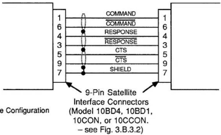
Fig. 3.B.3.3 RS-485 Satellite Cable Configuration
4. SETTING INTERFACE PROTOCOL FOR "A-SIZED" DATAPAC SATELLITES
The SATELLITE INTERFACE PORT furnished by the HOST DataPAC's Model 10BD4 is preset at the factory to recognize the following serial-ASCII interface protocol values, for both transmission and reception of data:
153.6K BAUD, 8 DATA BITS, 2 STOP BITS, ODD PARITY
(for an explanation of data-transfer "protocol," see Section 2.B.2 of this Guidebook).
Every SATELLITE SLAVE PORT (Model 10BD1) and CONSOLE INTERFACE PORT (Model 10CON or 10CCON) is also preset to recognize these same protocol values.
However, since every "A-SIZED" DataPAC SATELLITE connects to the network via its COMPUTER INTERFACE PORT, YOU MUST MAKE SURE THAT EACH SUCH INTERFACE IS SET TO RECOGNIZE THE ABOVE PROTOCOL VALUES. THIS IS ABSOLUTELY NECESSARY IN ORDER FOR PROPER DATA AND COMMAND INTERCHANGES BETWEEN THE DATAPAC AND THE SATELLITE NETWORK TO OCCUR.
You must therefore set the "A-sized" DataPAC's PROTOCOL SWITCHES to match the above (required) protocol. Consult Section 2.B.2(b) of this Guidebook for full instructions (remember that the BAUD RATE (BAU) command WILL NOT WORK WITH "A-SIZED" DATAPACS).
---- PLEASE NOTE ----
As explained in the Appendix to this Guidebook section, it is not an easy matter to change the network GLOBAL-CHANNEL and/or GLOBAL-BIT-GROUP assignments once these have been originally set up. In fact, the channel-range procedure involves the COMPLETE RECONFIGURATION (INCLUDING RECALIBRATION) OF ALL ORIGINALLY ASSIGNED DATA CHANNELS FOR THE HOST DATAPAC AND ALL "B-SIZED" DATAPAC SATELLITES. CAREFUL PLANNING PRIOR TO SETUP OF THE SATELLITE NETWORK CAN REDUCE THE PROBABILITY THAT A CHANGE OF THIS TYPE WILL BE NEEDED.
In particular, you may wish, during initial setup, to add a number of DOWNLOAD PSEUDOCHANNELS ("TYPE D0") to the end of each SATELLITE SCAN RANGE. This will allow for future expansion within each SATELLITE DataPAC and will reduce the likelihood of losing vital system calibration due to reconfiguration.
3.B.3 Satellite Network Systems
5. SETTING UP "GLOBAL" DATA CHANNELS
a. SETTING HOST AND SATELLITE SCAN RANGES: TER AND SCN COMMANDS
PLEASE NOTE
As mentioned in Section a.3, above, the procedures here given have been somewhat simplified for the sake of ease of setup. MORE COMPLEX TECHNIQUES INVOLVING RUN-TIME MODIFICATION OF SATELLITE SCAN RANGES FOR THE PURPOSE OF SPEED ENHANCEMENT ARE GIVEN IN APPENDIX K OF THIS GUIDEBOOK.
NOTE ALSO THAT OPERATOR CONSOLE SATELLITES DO NOT REQUIRE SCAN RANGE SETTINGS.
1. SETTING HOST SCAN RANGE
Set the HOST DataPAC to scan all active GLOBAL DATA CHANNELS by turning ON its EEPROM Switch and applying a TERMINATOR (TER) command of
$$ \mathbf {T E R} = \mathbf {x} [ \mathbf {C R} ] ^ {*} $$
where "x" is a Channel Number equal to that of the highest-numbered GLOBAL DATA CHANNEL to be dedicated to any DataPAC SATELLITE in the network. This command specifies a powerup-default SCAN RANGE from Channel No. 1 to and including Channel No. x.
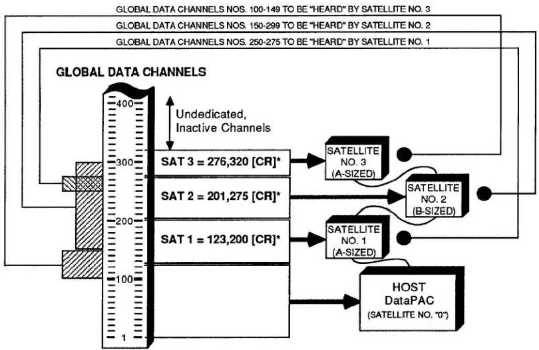
For the simple network shown in Fig. 3.B.3.4, for example, you would set the HOST'S SCAN RANGE by designating Channel No. 320 (the network's highest active GLOBAL DATA CHANNEL) to be the TERMINATOR CHANNEL, via a command of
$$ \mathrm{TER} = 3 2 0 [ \mathrm{CR} ] ^ {*} $$
2. SETTING THE SCAN RANGE FOR EACH DATAPAC SATELLITE
For each DataPAC SATELLITE in the network, you should set a SCAN RANGE that contains all GLOBAL DATA CHANNELS to be "heard" by that SATELLITE-i.e., all channels you wish the SATELLITE to be able to read and/or display. For an "A-sized" DataPAC SATELLITE, this normally includes all channels dedicated to the SATELLITE via the SATELLITE (SAT) command (Section b.5(b), below), plus all 10BD4-downloaded channels that have been given a local "TYPE" code of "D4" (see Section b.5(c)). For a "B-sized" DataPAC SATELLITE, it normally includes all channels dedicated to the SATELLITE via the SAT command, plus all channels that have been locally "located" to the SATELLITE'S Model 10BD1 Satellite Slave Card (see Section b.5(d)).
If the lowest-numbered GLOBAL DATA CHANNEL to be "heard" by the SATELLITE in question is GLOBAL DATA CHANNEL No. 1, you may set the SATELLITE'S SCAN RANGE by means of the TERMINATOR (TER) command (see above). In this case, the specified TERMINATOR CHANNEL for the SATELLITE will be the highest-numbered GLOBAL DATA CHANNEL to be "heard" by the SATELLITE.
If the lowest-numbered GLOBAL DATA CHANNEL to be "heard" by the SATELLITE in question is higher than GLOBAL DATA CHANNEL No. 1, you may use the following SCAN (SCN) command, having first turned ON the SATELLITE's EEPROM Switch (though the SCAN (SCN) command is normally used as a "RUN-TIME" COMMAND, it may also be used,
as in the present case, to define a "default" SCAN RANGE for the DataPAC, when the DataPAC's EEPROM is enabled (see Section 1.F.1 of this Guidebook for full details)):
$$ \mathbf {S C N} = \mathbf {x}, \mathbf {y} [ \mathbf {C R} ] ^ {*} $$
where Channel No. x is the lowest-numbered GLOBAL DATA CHANNEL to be "heard" by the SATELLITE and Channel No. y is the highest.
b. DEDICATING GLOBAL CHANNELS TO DATAPAC SATELLITES AND TO THE HOST: SAT COMMAND
The SATELLITE (SAT) command lets you designate any DataPAC SATELLITE to be the exclusive "data origin" for a specific GLOBAL DATA CHANNEL or range of GLOBAL DATA CHANNELS. Whenever interrogated by the Model 10BD4, this DataPAC SATELLITE will communicate all "locally" acquired data for its "dedicated" channel(s) both to the 10BD4 itself and to all other members of the network.
You may use the "READ" form of the LOCATE (LCT) command at any time to learn the network member to which a given GLOBAL DATA CHANNEL has been dedicated, as well as the "local LOCATION" currently assigned to that channel (see Section c.2, below, for details).
IMPORTANT
The SATELLITE (SAT) command is always applied to the HOST DataPAC. In order for it to be effective, the HOST'S EEPROM Write Protect Switch must be ON. THE EEPROM SWITCH OF THE DATAPAC SATELLITE TO WHICH ONE OR MORE CHANNELS ARE BEING DEDICATED MUST ALSO BE ON.
The general form of the SATELLITE (SAT) command is
$$ \mathbf {S A T} \mathbf {n} = \mathbf {x}, \mathbf {y} [ \mathbf {C R} ] ^ {*} $$
where 2 ≤ x < y ≤ 997 . This command designates SATELLITE No. n to be the sole "data origin" for GLOBAL DATA CHANNEL Nos. x through y. Specifically, it informs the 10BD4 that each channel within SATELLITE No. n's "LOCAL"-CHANNEL range of x through y will now serve as the sole data origin for the like-numbered "GLOBAL" CHANNEL.
Note that the lowest-numbered channel that can be dedicated to a SATELLITE is Channel No. 2; CHANNEL NO. 1 MUST ALWAYS BE DEDICATED TO THE HOST. Channel Nos. 998 and 999 are "LOCAL" CHANNELS only, and are always dedicated, respectively, to TIME and DATE.
A single-channel form of the SAT command is also possible:
$$ \mathbf {S A T} \mathbf {n} = \mathbf {x} [ \mathbf {C R} ] ^ {*} $$
where 2 ≤ x ≤ 997 . This form, however, will rarely be used.
With reference to the SAT command, you should note that
- ANY AND ALL GLOBAL DATA CHANNELS BELOW THE LOWEST-NUMBERED CHANNEL DEDICATED TO ANY DATAPAC SATELLITE IN THE NETWORK WILL BE AUTOMATICALLY DEDICATED TO THE HOST. Since, as mentioned above, the lowest-numbered channel that can be dedicated to a SATELLITE is Channel No. 2, Channel No. 1 will always be dedicated to the HOST.
3.B.3 Satellite Network Systems
Note, however, that an interrogation of SAT O [CR] is not presently effective; it will not return the channel(s) currently dedicated to the HOST.
- ANY AND ALL GLOBAL DATA CHANNELS ABOVE THE HIGHEST-NUMBERED CHANNEL DEDICATED TO ANY DATAPAC SATELLITE WILL REMAIN INACTIVE AND WILL NOT BE USED BY THE SYSTEM.
- AS A GENERAL RULE, YOU SHOULD NOT LEAVE AN UNDEDICATED—AND THEREFORE INACTIVE—CHANNEL OR CHANNELS BETWEEN DEDICATED CHANNELS OR CHANNEL RANGES. That is, the total range of dedicated channels should be a continuous range, as in the example below.
Fig. 3.B.3.4 Setup of Global Data Channels
flowchart
graph TD
    A["GLOBAL DATA CHANNELS"] --> B["400"]
    B --> C["SAT 3 = 276,320 [CR"]*]
    B --> D["SAT 2 = 201,275 [CR"]*]
    B --> E["SAT 1 = 123,200 [CR"]*]
    B --> F["Undedicated, Inactive Channels"]
    B --> G["SATELLITE NO. 3 (A-SIZED)"]
    B --> H["SATELLITE NO. 2 (B-SIZED)"]
    B --> I["SATELLITE NO. 1 (A-SIZED)"]
    B --> J["HOST DataPAC (SATELLITE NO. "0")"]
    style A fill:#f9f,stroke:#333
    style B fill:#ccf,stroke:#333
    style C fill:#cfc,stroke:#333
    style D fill:#cfc,stroke:#333
    style E fill:#cfc,stroke:#333
    style F fill:#cfc,stroke:#333
    style G fill:#fcc,stroke:#333
    style H fill:#fcc,stroke:#333
    style I fill:#fcc,stroke:#333
    style J fill:#fcc,stroke:#333
Consider, for example, the system shown in Fig. 3.B.3.4. In setting up the network, three SATELLITE (SAT) commands are communicated to the HOST:
$$ \text { SAT } 1 = 1 2 3, 2 0 0 [ \mathrm{CR} ] ^ {*} $$
$$ \text { SAT } 2 = 2 0 1, 2 7 5 [ \mathrm{CR} ] ^ {*} $$
$$ \text { SAT 3 } = 2 7 6, 3 2 0 [ \mathrm{CR} ] ^ {*} $$
The first command designates SATELLITE No. 1 to be the "data origin" for GLOBAL CHANNEL Nos. 123 through 200; the second assigns GLOBAL CHANNEL Nos. 201 through 275 to SATELLITE No. 2; and the third assigns GLOBAL CHANNEL Nos. 276 through 320 to SATELLITE No. 3.
Since Channel No. 123 is the lowest-numbered channel dedicated to any SATELLITE, all channels below No. 123 (i.e., Nos. 1 through 122) are automatically dedicated to the HOST. And since Channel No. 320 is the highest-numbered channel dedicated to any SATELLITE, all channels above No. 320 remain inactive. Finally, the total range of dedicated channels is a continuous range, consisting as it does of three immediately adjacent subranges (123 to 200, 201 to 275, 276 to 320). It would have been inadvisable, for instance, to have dedicated Channel Nos. 123 through 174 to SATELLITE No. 1 and Channel Nos. 201 through 275 to SATELLITE No. 2, thus leaving Channel Nos. 175 through 200 as a range of undedicated channels between two successive dedicated ranges (see, however, Appendix K of this manual for exceptions to this rule).
NOTE
After one of a SATELLITE'S "LOCAL" DATA CHANNELS has been designated to be the sole "data origin" for the like-numbered "GLOBAL" CHANNEL, the existing setup characteristics of that local channel (TYPE, LOCATION, FILTER, LIMIT VALUES, etc.) will be automatically assumed by the corresponding GLOBAL CHANNEL.
THEREFORE, ANY MEMBER OF THE NETWORK (SATELLITE OR HOST) CAN NOW BE INTERROGATED FOR THESE SETUP VALUES. ALSO, ANY OF THESE VALUES CAN NOW BE MODIFIED, IF DESIRED, THROUGH AN APPROPRIATE SETUP COMMAND (TYP, LCT, FIL, HIL, LOL, etc.) ENTERED THROUGH ANY MEMBER OF THE NETWORK (SATELLITE OR HOST). See Sections c.1 through c.5, below, for the "global" routing of INTERROGATIVE and SETUP COMMANDS.
To cancel a SAT assignment, thus instructing SATELLITE No. n to stop communicating "locally acquired" analog data to the Model 10BD4, you may apply to the HOST a command of
$$ \mathbf {S A T} \mathbf {n} = \mathbf {N} / \mathbf {A} [ \mathbf {C R} ] ^ {*} $$
NOTE
The above command serves to disconnect SATELLITE No. n from the network as an analog "data origin." It will have the effect of "globally" resetting all channels formerly dedicated to SATELLITE No. n by a previous SAT command. It will reset these channels, that is, from the network's point of view (only). IT WILL NOT AFFECT THE EXISTING SETUP CHARACTERISTICS OF ANY OF SATELLITE NO. n'S OWN "LOCAL" CHANNELS. ONLY THE CORRESPONDING "GLOBAL" CHANNELS ARE RESET.
Thus, if you were to ask any member of the network for the "TYPE" or "LOCATION" of a GLOBAL DATA CHANNEL that has been reset via a SAT n = N/A [CR] * command applied to some other SATELLITE, you will get an answer of D0 or N/A, respectively. However, if you follow a SAT n = N/A [CR] * command with an inquiry of TYP x [CR] or LCT x [CR] entered at SATELLITE No. n itself, you will be answered with the local "TYPE" or "LOCATION" designation still in effect for that SATELLITE'S Channel No. x. (This channel is now no longer "global"; it no longer serves as "data origin" for the network's like-numbered GLOBAL DATA CHANNEL, since the SATELLITE in which it resides has been effectively disconnected from the network. See Appendix K of this Guidebook for a consideration of "NONGLOBAL" SATELLITE DATA CHANNELS.)
C. SETTING AN "A-SIZED" DATAPAC SATELLITE TO "HEAR" GLOBAL CHANNELS NOT DEDICATED TO THAT SATELLITE: DLC AND TYP COMMANDS
To arrange for an "A-sized" DataPAC SATELLITE to be able to read and/or display one or more GLOBAL DATA CHANNELS that have not been dedicated to that SATELLITE itself via an appropriate SATELLITE (SAT) command, you should
1. SPECIFY GLOBAL CHANNELS TO BE DOWNLOADED TO ALL "A-SIZED" SATELLITES BY THE 10BD4
A DOWNLOAD CHANNELS (DLC) command should be applied to the HOST DataPAC, designating the GLOBAL DATA CHANNEL or range of GLOBAL DATA CHANNELS to be downloaded—with each 10BD4 scan cycle—to every "A-sized" DataPAC SATELLITE in the network. To so designate all GLOBAL DATA CHANNELS from Channel No. x to and including Channel No. y, command
$$ \mathbf {D L C} = \mathbf {x}, \mathbf {y} [ \mathbf {C R} ] ^ {*} $$
Here, Channel No. x is the lowest-numbered GLOBAL DATA CHANNEL to be "heard" by any "A-sized" DataPAC SATELLITE to which it has not been dedicated, while Channel No. y is the highest.
NOTE
Since the automatic downloading of channels by the 10BD4 slows down its overall scan speed, the DLC range should be kept as short as possible. It should only include those GLOBAL DATA CHANNELS which are to be "heard" by one or more "A-sized" DataPAC SATELLITES.
Like the SAT command, the DLC command also has a single-channel form, which is rarely used:
$$ \mathbf {D L C} = \mathbf {x} [ \mathbf {C R} ] ^ {*} $$
You may cancel the 10BD4's automatic downloading of GLOBAL DATA CHANNELS to all "A-sized" SATELLITES by applying to the HOST a command of
$$ \mathbf {D L C} = \mathbf {N} / \mathbf {A} [ \mathbf {C R} ] ^ {*} $$
2. CHECK SATELLITE SCAN RANGE
Make sure that the "A-sized" DataPAC SATELLITE in question has been set to scan all of the 10BD4-downloaded GLOBAL DATA CHANNELS you want it to be able to read and/or display (see Section b.5(a), above). TO MAXIMIZE ITS OWN SCAN RATE, IT SHOULD NOT BE MADE TO SCAN CHANNELS IT DOES NOT NEED TO "HEAR."
3. RETYPE AS "D4" ALL DOWNLOADED CHANNELS TO BE "HEARD" BY THE SATELLITE
Apply one or more TYPE (TYP) commands to the "A-sized" DataPAC SATELLITE, in order to assign a local "TYPE" code of "D4" to each 10BD4-downloaded GLOBAL DATA CHANNEL which is to be "heard" by the SATELLITE and which has not been dedicated to the SATELLITE via the SAT command (see the example below). Be sure to turn ON the SATELLITE'S EEPROM Switch before entering the necessary TYPE (TYP) command(s).
REMEMBER THAT ANY GLOBAL DATA CHANNEL OR CHANNELS FOR WHICH THE "A-SIZED" DATAPAC SATELLITE IS ITSELF THE UNIQUE "DATA ORIGIN" SHOULD NOT BE GIVEN A LOCAL "TYPE" CODE OF "D4." SUCH CHANNELS ALREADY HAVE THEIR OWN LOCAL TYP ASSIGNMENTS AND ARE ALREADY "HEARD" BY THE SATELLITE.
For example, suppose that SATELLITE Nos. 1 and 3 in Fig. 3.B.3.4 are both "A-sized" DataPACs. Suppose too that, in addition to its "dedicated" range of Channel Nos. 123 through 200, you want SATELLITE No. 1 to be able to read Channel Nos. 250 through 275, and that you want SATELLITE No. 3 to be able to read Channel Nos. 100 through 149, in addition to its "dedicated" range of Channel Nos. 276 through 320.
You will first apply to the HOST DataPAC a command of
$$ \mathrm{DLC} = 1 0 0, 2 7 5 [ \mathrm{CR} ] ^ {*} $$
This defines the range of GLOBAL DATA CHANNELS to be downloaded with each 10BD4 scan cycle to both "A-sized" SATELLITES (since the lowest channel to be "heard" by an "A-sized" SATELLITE to which it has not been dedicated is No. 100, and the highest is No. 275). You should now make sure that each SATELLITE is set to scan all channels you want it to be able to read (including, of course, those which have been dedicated to it via the SAT command). Thus, for SATELLITE No. 1, the SCAN RANGE should be (at least) from Channel No. 123 through No. 275, and for SATELLITE No. 3, from Channel No. 100 through No. 320. Then apply to SATELLITE No. 1 a command of
$$ \text { TYP 250 TO 275 } = \text { D4 [CR] } ^ {*} $$
and to SATELLITE No. 3 a command of
$$ \text { TYP 100 TO 149 } = \text { D4 [CR] } ^ {*} $$
d. SETTING A "B-SIZED" DATAPAC SATELLITE TO "HEAR" GLOBAL DATA CHANNELS NOT DEDICATED TO THAT SATELLITE: LCT AND RST COMMANDS
Every OPERATOR CONSOLE SATELLITE will always "hear" all GLOBAL DATA CHANNELS—that is, it will always be able to read any GLOBAL CHANNEL when so interrogated or to display any GLOBAL CHANNEL when a "local" VIDEO PAGE FORMAT has been composed that contains a DATA FIELD for that channel.
Like an OPERATOR CONSOLE SATELLITE, a "B-sized" DataPAC SATELLITE will always be in receipt of all GLOBAL DATA. However, to arrange for the SATELLITE to be able to actually read and/or display one or more GLOBAL DATA CHANNELS that have not been dedicated to that SATELLITE itself via an appropriate SAT command, you should
1. "RELOCATE" ALL UNDEDICATED CHANNELS TO THE SATELLITE'S MODEL 10BD1
A special form of the LOCATE (LCT) command lets you "LOCATE" to the SATELLITE'S Model 10BD1 Satellite Slave Card a GLOBAL DATA CHANNEL or range of GLOBAL DATA CHANNELS outside the range of channels dedicated to the SATELLITE itself. The 10BD1 becomes the local "LOCATION" for each such channel—that is, its apparent physical origin from the SATELLITE'S point of view (only). With each of its own scan cycles, the SATELLITE'S CENTRAL PROCESSOR will thus be referred to the 10BD1 for the channel's current data value. Note that we do not thereby specify an actual "local physical origin" for the channel at the SATELLITE in question; this origin continues to reside in the particular network member to which the channel has been dedicated via the SATELLITE (SAT) command.
3.B.3 Satellite Network Systems
If the Model 10BD1 occupies the SATELLITE'S B SLOT No. s, then to "LOCATE" to the 10BD1 all GLOBAL DATA CHANNELS from Channel No. x through Channel No. y, you would apply the following command to the SATELLITE itself, after turning ON its EEPROM Switch:
$$ \mathbf {L C T} \times \mathbf {T O} \mathbf {y} = \mathbf {s} [ \mathbf {C R} ] ^ {*} $$
Like the SAT and DLC commands, the LCT command also has a single-channel form, which is rarely used in this application:
$$ \mathbf {L C T} \mathbf {x} = \mathbf {s} [ \mathbf {C R} ] ^ {*} $$
REMEMBER THAT ANY GLOBAL DATA CHANNEL OR CHANNELS FOR WHICH THE "B-SIZED" DATAPAC SATELLITE IS ITSELF THE UNIQUE "DATA ORIGIN" SHOULD NOT BE LOCALLY "LOCATED" TO THE SATELLITE'S MODEL 10BD1 CARD. SUCH CHANNELS ALREADY HAVE THEIR OWN LOCAL LCT ASSIGNMENTS AND ARE ALREADY "HEARD" BY THE SATELLITE.
Because for each "B-sized" DataPAC SATELLITE there will almost always be a range of GLOBAL DATA CHANNELS dedicated to the SATELLITE itself via the SAT command, the multichannel "B-SLOT LCT" command will in most cases have to be applied twice: once with reference to all GLOBAL DATA CHANNELS below the lowest-numbered channel dedicated to the SATELLITE, and the second time with reference to all GLOBAL DATA CHANNELS above the highest-numbered channel dedicated to the SATELLITE. As in the example below, the second LCT command may include inactive GLOBAL DATA CHANNELS-i.e., those above the total range of dedicated channels-without detriment to system speed or operation.
2. CHECK SATELLITE SCAN RANGE
Make sure that the "B-sized" DataPAC SATELLITE in question has been set to scan all GLOBAL DATA CHANNELS you want it to be able to read and/or display (see Section b.5(a), above).
Refer again to Fig. 3.B.3.4. GLOBAL DATA CHANNEL Nos. 201 through 275 have been dedicated to SATELLITE No. 2 via the second SATELLITE (SAT) command. Suppose that this SATELLITE is a "B-sized" DataPAC whose Model 10BD1 occupies B SLOT No. 4. Suppose too that you want the SATELLITE to be able to read and display all GLOBAL DATA CHANNELS from Channel No. 150 through Channel No. 299. Two LOCATE (LCT) commands should first be applied to SATELLITE No. 2:
$$ \text { LCT 1 TO 200 } = 4 \text {[CR]} ^ {} \text { and } \text { LCT 276 TO 997 } = 4 \text {[CR]} ^ {} $$
This "locates" to the 10BD1 all GLOBAL DATA CHANNELS outside the range of channels dedicated to the SATELLITE itself (Nos. 201 through 275). You should then set the SATELLITE'S SCAN RANGE to include all channels you want it to be able to read and display (including, of course, those which have been dedicated to it via the SAT command). In the present example, this SCAN RANGE should be (at least) from Channel No. 150 through No. 299.
To discontinue the reading of a given channel or range of channels by a "B-sized" DataPAC SATELLITE, you may change the SATELLITE'S current SCAN RANGE, if possible, to exclude the channel(s) in question. Or you may issue to the SATELLITE itself a RESET (RST) command of either
$$ R S T \times [ C R ] ^ {} \text { or } R S T \times T O y [ C R ] ^ {} $$
NOTE
A RESET (RST) COMMAND IS NECESSARY IF YOU WISH TO ASSIGN A NEW LOCAL "LOCATION" TO ANY CHANNEL CURRENTLY "LOCATED" TO A SATELLITE'S MODEL 10BD1 SATELLITE SLAVE CARD. Since it is not "implicitly addressed" (Section c.1), RST will only reset the "local" characteristics of the channel or channels to which it applies; IT WILL NOT RESET THE CHANNEL OR CHANNELS "GLOBALLY."
6. SETTING UP "GLOBAL" LOGIC BITS
NOTE
The procedures in this section are largely analogous to those given in Section b.5, above, for dedicating GLOBAL DATA CHANNELS to network members, and for setting an "A-" or "B-sized" DataPAC SATELLITE to "hear" GLOBAL DATA CHANNELS that are not dedicated to it. NOTE, HOWEVER, THAT WHEN LOGIC BITS ARE INVOLVED, YOU NEED NOT WORRY ABOUT "SCAN RANGE." YOU MUST, HOWEVER, BE SURE THAT THE BITS (BTS) COMMAND IS IN EFFECT FOR BOTH THE HOST DATAPAC AND THE DATAPAC SATELLITE IN QUESTION (see Section 2.H.5 of this Guidebook). BTS is in effect, by default, on DataPAC powerup.
Note too that any DataPAC SATELLITE may be loaded with EXECUTE (EXU) command strings, each of which will be automatically triggered on perception by the SATELLITE of the logic-state transition of a specified GLOBAL LOGIC BIT (see Section 2.K. of this Guidebook for a full description of the EXECUTE (EXU) command). Obviously, the DataPAC SATELLITE must be capable of reading any and all "trigger bits" assigned to its individual EXU function(s). See also Section b.8, below, for the setup of a SATELLITE'S "EXECUTE BASE GROUPS."
a. DEDICATING GLOBAL BIT GROUPS TO DATAPAC SATELLITES AND TO THE HOST: SSB COMMAND
NOTE
YOU CANNOT ASSIGN A LOCAL "DATA ORIGIN" TO AN INDIVIDUAL GLOBAL LOGIC BIT. YOU CAN ONLY DEDICATE GLOBAL LOGIC BITS TO PARTICULAR SATELLITES IN TERMS OF 16-MEMBER BIT GROUPS.
ALSO, DO NOT CONFUSE THE ASSIGNING OF A UNIQUE "DATA ORIGIN" (SATELLITE) TO A GIVEN GLOBAL BIT GROUP WITH THE ASSIGNING OF A UNIQUE LOCAL "LOGIC SOURCE" TO EACH BIT WITHIN THAT GROUP (see Section 2.H of this Guidebook for a full discussion of BIT GROUPS and LOGIC SOURCES).
The SATELLITE SYSTEM BITS (SSB) command lets you designate any DataPAC SATELLITE to be the exclusive "data origin" for a specific GLOBAL BIT GROUP or range of GLOBAL BIT GROUPS.
You may use the "READ" form of the LOGIC SOURCE (SRC) command at any time to learn the network member to which a given GLOBAL LOGIC BIT (not BIT GROUP) has been dedicated, and also the local LOGIC SOURCE currently assigned to that bit (see Section c.3, below, for details).
3.B.3 Satellite Network Systems
IMPORTANT
As with the SATELLITE (SAT) command, the SATELLITE SYSTEM BITS (SSB) command is always applied to the HOST DataPAC. In order for it to be effective, the HOST'S EEPROM Write Protect Switch must be ON. THE EEPROM SWITCH OF THE SATELLITE TO WHICH ONE OR MORE BIT GROUPS ARE BEING DEDICATED MUST ALSO BE ON.
The general form of the SATELLITE SYSTEM BITS (SSB) command is either
$$ \begin{array}{l} \mathbf {S S B} \mathbf {n} = \mathbf {k} [ \mathbf {C R} ] ^ {} \ \mathbf {S S B} \mathbf {n} = \mathbf {k}, \mathbf {I} [ \mathbf {C R} ] ^ {} \ \end{array} $$
or
NOTE: The number "n" should be from 1 through 99; it should NEVER be "0."
depending on whether you wish to dedicate to DataPAC SATELLITE No. n a single GLOBAL BIT GROUP (No. k) or a continuous range of GLOBAL BIT GROUPS (Nos. k through l).
For example, a command of
$$ \text { SSB } 1 0 = 2, 4 [ \mathrm{CR} ] ^ {*} $$
establishes each LOGIC BIT within SATELLITE No. 10's BIT GROUP Nos. 2, 3, and 4 as the sole "data origin" for the corresponding (like-numbered) GLOBAL BIT.
With reference to the SSB command, you should note that
- ANY AND ALL GLOBAL BIT GROUPS BELOW THE LOWEST-NUMBERED BIT GROUP DEDICATED TO ANY DATAPAC SATELLITE IN THE NETWORK WILL BE AUTOMATICALLY DEDICATED TO THE HOST. Note, however, that an interrogation of SSB 0 [CR] is not presently effective; it will not return the BIT GROUP(S) currently dedicated to the HOST.
- ANY AND ALL GLOBAL BIT GROUPS ABOVE THE HIGHEST-NUMBERED BIT GROUP DEDICATED TO ANY DATAPAC SATELLITE WILL REMAIN INACTIVE AND WILL NOT BE USED BY THE SYSTEM.
- THE TOTAL RANGE OF DEDICATED BIT GROUPS NEED NOT BE A CONTINUOUS RANGE.
NOTE
After one of a SATELLITE'S "LOCAL" BIT GROUPS has been designated to be the sole "data origin" for the like-numbered "GLOBAL" BIT GROUP, the existing LOGIC-SOURCE assignment for each bit in the local BIT GROUP will be automatically assumed by the corresponding GLOBAL BIT.
THEREFORE, ANY MEMBER OF THE NETWORK (SATELLITE OR HOST) CAN NOW BE INTERROGATED FOR THE LOGIC SOURCE OF ANY BIT WITHIN THIS BIT GROUP. ALSO, THIS LOGIC-SOURCE ASSIGNMENT CAN NOW BE MODIFIED, IF DESIRED, THROUGH AN APPROPRIATE LOGIC SOURCE (SRC) COMMAND ENTERED THROUGH ANY MEMBER OF THE NETWORK (SATELLITE OR HOST). See Sections c.1 through c.5, below, for the "global" routing of INTERROGATIVE and SETUP COMMANDS.
To cancel an SSB assignment, thus instructing SATELLITE No. n to stop communicating "locally acquired" logic data to the Model 10BD4, you may apply to the HOST a command of
$$ \mathbf {S S B} \mathbf {n} = \mathbf {N} / \mathbf {A} [ \mathbf {C R} ] ^ {*} $$
NOTE
The above command serves to disconnect SATELLITE No. n from the network as a logic "data origin." It will have the effect of "globally" re-sourcing all bits formerly dedicated to SATELLITE No. n by a previous SSB command. It will re-source these bits, that is, from the network's point of view (only). IT WILL NOT AFFECT THE EXISTING LOGIC-SOURCE ASSIGNMENTS OF ANY OF SATELLITE NO. n'S OWN "LOCAL" BITS. ONLY THE CORRESPONDING "GLOBAL" LOGIC BITS ARE RE-SOURCED.
Thus, if you were to ask any member of the network for the LOGIC SOURCE of a GLOBAL LOGIC BIT that has been re-sourced via an SSB n = N/A [CR] * command applied to some other SATELLITE, you will get an answer of EXT, NON. However, if you follow an SSB n = N/A [CR] * command with an inquiry of SRC r [CR] entered at SATELLITE No. n itself, you will be answered with the local LOGIC-SOURCE still in effect for that SATELLITE'S Bit No. r. (This bit is now no longer "global"; it no longer serves as "data origin" for the network's like-numbered GLOBAL LOGIC BIT, since the SATELLITE in which it resides has been effectively disconnected from the network. See Appendix K of this Guidebook for a consideration of "NONGLOBAL" SATELLITE DATA CHANNELS.)
b. SETTING AN "A-SIZED" DATAPAC SATELLITE TO "HEAR" GLOBAL LOGIC BITS NOT DEDICATED TO THAT SATELLITE: DLB AND SRC COMMANDS
1. SPECIFY GLOBAL BIT GROUPS TO BE DOWNLOADED TO ALL "A-SIZED" SATELLITES BY THE 10BD4
A DOWNLOAD BITS (DLB) command should be applied to the HOST DataPAC, designating the GLOBAL BIT GROUP or range of GLOBAL BIT GROUPS to be downloaded—with each 10BD4 scan cycle—to every "A-sized" DataPAC SATELLITE in the network. Command, respectively,
$$ \mathbf {D L B} = \mathbf {k} [ \mathbf {C R} ] ^ {} \text {or} \mathbf {D L B} = \mathbf {k}, I [ \mathbf {C R} ] ^ {} $$
This command is analogous to the DOWNLOAD CHANNELS (DLC) command discussed in Section b.5(c), above (see this section for details and example).
NOTE
Since the automatic downloading of BIT GROUPS by the 10BD4 slows down its overall scan speed, the DLB range should be kept as short as possible. It should include only those GLOBAL BIT GROUPS to be "heard" by one or more "A-sized" DataPACs.
To cancel the 10BD4's automatic downloading of GLOBAL BIT GROUPS to all "A-sized" SATELLITES, apply to the HOST a command of
$$ \mathbf {D L B} = \mathbf {N} / \mathbf {A} [ \mathbf {C R} ] ^ {*} $$
3.B.3 Satellite Network Systems
2. RE-SOURCE AS "SAT" ALL DOWNLOADED BITS TO BE "HEARD" BY THE SATELLITE
Apply to the "A-sized" DataPAC one or more LOGIC SOURCE (SRC) commands of the single-bit or range form—
$$ \text { SRC } r = \text { SAT } [ \text { CR } ] ^ {} \text { or } \text { SRC } r \text { TO } q = \text { SAT } [ \text { CR } ] ^ {} $$
respectively-in order to assign a local LOGIC SOURCE of "SAT" to each GLOBAL LOGIC BIT within the GLOBAL BIT GROUP(S) specified by the DLB command, above, which is to be "heard" by the SATELLITE and which has not been dedicated to the SATELLITE via the SSB command.
REMEMBER THAT ANY GLOBAL LOGIC BIT CONTAINED IN A BIT GROUP FOR WHICH THE "A-SIZED" DATAPAC SATELLITE IS ITSELF THE UNIQUE "DATA ORIGIN" SHOULD NOT BE GIVEN A LOCAL LOGIC SOURCE OF "SAT." SUCH BITS ALREADY HAVE THEIR OWN LOCAL SRC ASSIGNMENTS AND ARE ALREADY "HEARD" BY THE SATELLITE (ASSUMING THE BTS COMMAND IS IN EFFECT).
C. SETTING A "B-SIZED" DATAPAC SATELLITE TO "HEAR" GLOBAL LOGIC BITS NOT DEDICATED TO THAT SATELLITE: SRC AND NOB COMMANDS
A special form of the LOGIC SOURCE (SRC) command lets you "source" to the SATELLITE'S Model 10BD1 Satellite Slave Card a GLOBAL LOGIC BIT or range of GLOBAL LOGIC BITS outside the range of BIT GROUPS dedicated to the SATELLITE itself. The 10BD1 becomes the local LOGIC SOURCE for each such bit—that is, its apparent bit-state determinant from the SATELLITE'S point of view (only). With each of its own scan cycles, the SATELLITE'S CENTRAL PROCESSOR will thus be referred to the 10BD1 for the bit's current state. Note that we do not thereby specify an actual "LOGIC SOURCE" for the bit at the SATELLITE in question; this continues to reside in the particular network member to which the bit has been dedicated via the SATELLITE SYSTEM BITS (SSB) command.
If the Model 10BD1 occupies the SATELLITE'S B SLOT No. s, then to "source" to the 10BD1 all GLOBAL LOGIC BITS from Bit No. r through Bit. No. q, you would apply the following command to the SATELLITE itself, after turning ON its EEPROM Switch:
$$ \text { SRC } \mathbf {r} \text { TO } \mathbf {q} = \text { Bs } [ \text { CR } ] ^ {*} $$
In this command, the letter "B" must immediately precede the B-SLOT No. "s."
The SRC command also has a single-bit form, which is rarely used in this application:
$$ \text { SRC } r = \text { Bs } [ \text { CR } ] ^ {*} $$
Note that, unlike the SATELLITE SYSTEM BITS (SSB) and DOWNLOAD BITS (DLB) commands, above, the LOGIC SOURCE (SRC) command refers to one or a range of individual LOGIC BITS, and not to one or a range of BIT GROUPS.
REMEMBER TOO THAT ANY GLOBAL BIT CONTAINED IN A BIT GROUP FOR WHICH THE "B-SIZED" DATAPAC IS ITSELF THE UNIQUE "DATA ORIGIN" SHOULD NOT BE LOCALLY "SOURCED" TO THE SATELLITE'S MODEL 10BD1. SUCH BITS ALREADY HAVE THEIR OWN LOCAL SRC ASSIGNMENTS AND ARE ALREADY "HEARD" BY THE SATELLITE (ASSUMING THE BTS COMMAND IS IN EFFECT).
The "range" form of the "B-SLOT SRC" command will in almost all cases have to be applied twice: once with reference to all GLOBAL LOGIC BITS below the lowest-numbered bit of the lowest-numbered BIT GROUP dedicated to the SATELLITE, and the second time with reference to all GLOBAL LOGIC BITS above the highest-numbered bit of the highest-numbered BIT GROUP dedicated to the SATELLITE. The second SRC command may include
inactive GLOBAL LOGIC BITS—i.e., those above the total range of dedicated BIT GROUPS—without detriment to system speed or operation.
For example, suppose that a given "B-sized" DataPAC SATELLITE has been made the "data origin" for GLOBAL BIT GROUP Nos. 3 through 5 (total system GLOBAL LOGIC-BIT capacity is always 1000). The LOGIC-BIT range that corresponds to this BIT-GROUP range is Bit No. 32 through Bit No. 79. The SATELLITE'S Model 10BD1 Satellite Slave Card occupies B SLOT No. 2. In setting up this SATELLITE, you would therefore issue to it the following SRC commands:
$$ \text { SRC 0 TO 31 } = \text { B2 [CR] } ^ {} \text { and } \text { SRC 80 TO 999 } = \text { B2 [CR] } ^ {} $$
To discontinue the "hearing" of all LOGIC BITS by a "B-sized" DataPAC SATELLITE (including those that have been dedicated to it via the SSB command), you can instruct the SATELLITE'S CENTRAL PROCESSOR to stop the scanning of bits by applying to the SATELLITE a NO BITS (NOB) command:
NOB [CR]
(see Section 2.H.5 of this Guidebook—this command will also disable all EXECUTE (EXU) functions for the SATELLITE).
To discontinue the "hearing" of a given range of GLOBAL LOGIC BITS (Nos. r through q) that have been locally "sourced" to the SATELLITE'S Model 10BD1, you can "re-source" them to "EXTERNAL" by applying to the SATELLITE a command of
$$ \text { SRC } r \text { TO } q = \text { EXT } [ \text { CR } ] ^ {*} $$
7. SETTING HOST AND SATELLITES FOR LOCAL DATA ACQUISITION AND FOR DISPLAY OF GLOBAL DATA
FOR EVERY OPERATOR CONSOLE SATELLITE IN THE NETWORK, apply to the HOST DataPAC a command of
$$ \mathbf {S A T} \mathbf {n} = \mathbf {C O N} [ \mathbf {C R} ] ^ {*} $$
where "n" is the respective SATELLITE NUMBER.
Each member of the network should now be set up with regard to its own independent data-acquisition, process-control, and/or data-display functions.
You are here referred to the relevant sections of this Guidebook. See the Table of Contents. Among the most important "local" setup procedures are
a. DataPAC POWERUP and KEYBOARD CONNECTION (Sections 1.B and 1.C)
b. CABLING OF ANALOG INPUTS (Section 1.E)
c. CRT VIDEO SETUP of "B-sized" DataPACs and OPERATOR CONSOLES (Sections 1.D.2 and 2.C); LCD VIDEO SETUP of certain "A-sized" DataPAC SATELLITES (Sections 1.D.1 and 2.Q)
d. DataPAC "REAL"-CHANNEL CONFIGURATION and CALIBRATION (Section 1.G)
e. DATA-CHANNEL LIMIT SETUP (Section 2.F)
f. PSEUDOCHANNEL SETUP (Sections 2.D, 2.J, 2.L, 2.M, 3.B.4(d.8), etc.)
g. SETUP OF LOGIC BITS (Section 2.H)
3.B.3 Satellite Network Systems
h. SETUP OF LOGIC I/O for optional Model 10AIO-16 or 10BIO-16 (Section 3.A.3 or 3.B.2)
i. CABLING AND SETUP OF "B-SIZED" DATAPAC'S COMPUTER INTERFACE PORT AND OPTIONAL AUXILIARY COMPUTER INTERFACE PORT (ACI) (Sections 2.B and 3.B.5)
j. SETUP OF EXECUTE (EXU) and COMMAND (CMD) FUNCTIONS (the latter for "B-sized" DataPACs only—Section 2.K and also Section b.8, below)
Note that since most DATA-CHANNEL SETUP COMMANDS are "implicitly addressed," they will be automatically routed to the specific network members to which they apply, when entered either at the HOST or at any "B-sized" DataPAC SATELLITE where the GBL = ON [CR] command is in effect (see Section c.1, below). Note too that any SETUP COMMAND can be "explicitly" routed to any given network member from any other network member, using the OPEN (OPN) or NODE (NOD) command (see Section c.5).
"Implicit" or "explicit" routing of SETUP COMMANDS can only be done, of course, after the SATELLITES involved have been assigned their respective SATELLITE NUMBERS (via the ASN command) and the required network interface has been fully established. In order for a "routed" SETUP COMMAND to be effective, the recipient SATELLITE'S EEPROM Write Protect Switch must be ON.
8. SETTING SATELLITE "EXECUTE BASE GROUPS": XBG COMMAND
In a SATELLITE NETWORK, each DataPAC SATELLITE can have its own group of 32 EXECUTE (EXU) strings, independent of all other SATELLITES. Each EXU string contained in a DataPAC SATELLITE may be triggered by any GLOBAL LOGIC BIT which is "heard" by that SATELLITE (see Section b.6, above).
The two BIT GROUPS used by a DataPAC to trigger EXECUTE (EXU) command strings constitute the DataPAC's "EXECUTE BASE GROUP." Normally a DataPAC is initially set to use its first two BIT GROUPS (i.e., Bit Nos. 0 through 31) for this purpose.
It will usually be desirable to assign to every DataPAC SATELLITE which is to be loaded with its own EXECUTE (EXU) strings an EXECUTE BASE GROUP different from that of any other DataPAC in the system, including the HOST. (This would not be case, however, if you ever wanted two or more DataPACs to simultaneously execute individual command strings on the logic-state transition of one single GLOBAL BIT.)
By means of the EXECUTE BASE GROUP (XBG) command, you can assign a DataPAC's EXECUTE (EXU) statements to the bits of any two BIT GROUPS, which need not be contiguous. The application of the XBG command is fully discussed in Section 2.K.2(c) of this manual.
Suppose, for example, that you want the HOST DataPAC to continue to use the first two GLOBAL BIT GROUPS for its EXU functions, while GLOBAL BIT GROUP Nos. 3 and 4 (i.e., GLOBAL BIT Nos. 32 through 63) are to be assigned to the EXU functions of a given DataPAC SATELLITE. You should then issue the following commands to the DataPAC SATELLITE, after turning ON its EEPROM Switch:
$$ \mathbf {X B G 1} = 3 [ \mathbf {C R} ] ^ {} \text { and } \mathbf {X B G 2} = 4 [ \mathbf {C R} ] ^ {} $$
If the SATELLITE has no keyboard (Model 10KU, 10K1, 10K4, etc.), you can send the XBG commands to the SATELLITE via the HOST'S keyboard, using the OPEN (OPN) or NODE (NOD) command, as explained in Section c.5, below, once a SATELLITE NUMBER has been assigned to the SATELLITE.
1. INTRODUCTION: GLOBAL COMMANDS
NOTE
For convenience in discussing the following "RUN-TIME" operations, we will call any member of the network (HOST or SATELLITE) a "NODE." Individual NODES, including the HOST DataPAC, are distinguished by their respective "SATELLITE NUMBERS" (see Section b.2, above). The SATELLITE NUMBER of the HOST is always "0."
A "GLOBAL COMMAND" is a command intended for a network NODE other than the one at which the command is actually entered. Such a command is said to be "IMPLICITLY ADDRESSED" if, having been entered at any "B-sized" DataPAC NODE where the GBL = ON [CR] command is in effect (see below), it is then automatically routed to the one specific "A-" or "B-sized" DataPAC NODE to which it applies. By virtue of the GLOBAL DATA CHANNEL(S) or GLOBAL LOGIC BIT(S) contained in the command itself, the HOST DataPAC's CENTRAL PROCESSOR knows immediately to which DataPAC NODE an implicitly addressed command is to be sent. It therefore needs no other ("explicit") instructions—such as an OPEN (OPN) or NODE (NOD) command—to direct the command to the proper DataPAC NODE.
For example, when entered at a "B-sized" NODE where the GBL = ON [CR] command is in effect, the HOST DataPAC knows immediately that a command of
HIL 593 [CR]
is meant for the DataPAC SATELLITE to which GLOBAL DATA CHANNEL No. 593 has been dedicated; or that a command of
$$ \text { SRC } 2 1 = \text { INP }, \text { NON } [ \text { CR } ] ^ {*} $$
is meant for the DataPAC SATELLITE to which GLOBAL BIT GROUP No. 2 (Bit Nos. 16 through 31) has been dedicated. Each of these commands contains its own "implicit address."
Implicitly addressed CHANNEL-related commands are as follows (except for CHN, both "WRITE" and "READ" forms are included):
ANO, BEE, "CHN=", CLC, CON, DEC, EMM, FIL, FRC, FRQ, HIL, INC, LBT, LCT, LGT, LLT, LOL, MVV, SHN, SHP, TAR, TYP, ZRO
Note that while the "WRITE" form of the CHANNEL (CHN) command is implicitly addressed, the "READ" form is not. Thus, to an interrogation of the form CHN x [CR], the "local" channel value will always be returned.
Note too that the RESET (RST) command is not in the above list; though it contains a specific DATA-CHANNEL argument, a GLOBAL RST command must be "explicitly" routed to be effective.
The only implicitly addressed BIT-related command (both "WRITE" and "READ") is LOGIC SOURCE (SRC).
IF A GIVEN COMMAND IS NOT IMPLICITLY ADDRESSED, THEN IN ORDER TO BE SENT FROM ONE NODE TO ANOTHER, IT MUST BE "EXPLICITLY" ADDRESSED BY MEANS OF THE OPEN (OPN) OR NODE (NOD) COMMAND, AS EXPLAINED IN SECTION c.5, BELOW.
The GLOBAL (GBL) command, discussed in Section c.4, below, may be used to disable the transmission of implicitly addressed commands from a given "B-sized" DataPAC NODE. To be effective, any GLOBAL COMMAND entered at a NODE at which the GBL = OFF [CR] command is in effect must be "explicitly addressed."
3.B.3 Satellite Network Systems
NOTE
GLOBAL COMMANDS CAN NOT BE "IMPLICITLY" ROUTED FROM AN "A-SIZED" DATAPAC SATELLITE OR FROM AN OPERATOR CONSOLE SATELLITE, FOR BOTH OF WHICH THE GBL = OFF [CR] CONDITION IS ALWAYS IN EFFECT. While such a SATELLITE may always receive "implicitly addressed" commands, any GLOBAL COMMAND to be issued by an "A-sized" DataPAC or OPERATOR CONSOLE SATELLITE must be "explicitly" routed via the OPEN (OPN) or NODE (NOD) command, as explained in Section c.5, below.
Because it is implicitly addressed, a LOCATE (LCT) or LOGIC SOURCE (SRC) interrogation referring to any GLOBAL DATA CHANNEL or GLOBAL LOGIC BIT can be entered at any "B-sized" NODE where the GBL = ON [CR] command is in effect. See Sections c.2 and c.3, below. It is also possible to enter at any such NODE the "range" forms of these commands (i.e., the LCT x TO y and SRC r TO q forms)—or of any other implicitly addressed "READ" or "WRITE" COMMAND.
When so doing, however, please note that IN ANY ONE GLOBAL COMMAND OF THE "RANGE" FORM, THE SPECIFIED RANGE CANNOT EXCEED THE RANGE OF CHANNELS OR BITS DEDICATED TO A SINGLE SATELLITE, OR "OVERLAP" BETWEEN DIFFERENT SATELLITES. THIS RULE ONLY APPLIES TO GLOBAL SETUP AND INTERROGATION COMMANDS THAT ARE "IMPLICITLY ADDRESSED."
For example, suppose that Channel Nos. 100 through 149 have been dedicated to one SATELLITE DataPAC, and Channel Nos. 150 through 199 to another. A GLOBAL COMMAND (entered, say, at the HOST DataPAC) of
HIL 125 TO 175 [CR]
would not be permitted, since it "crosses SATELLITE boundaries." Instead, you must respect the fact that two separately dedicated channel ranges are here involved by entering two different GLOBAL COMMANDS:
HIL 125 TO 149 [CR] and HIL 150 TO 175 [CR]
Note, however, that an interrogation of HIL 125 TO 175 [CR] may be legitimately entered as a LOCAL COMMAND to any given network DataPAC (SATELLITE or HOST) or may be "explicitly" routed to any given DataPAC via an OPEN (OPN) or NODE (NOD) command. A COMMAND OF THE "RANGE" FORM NEED OBSERVE SATELLITE BOUNDARIES ONLY WHEN IT IS ENTERED AS AN IMPLICITLY ADDRESSED GLOBAL COMMAND.
2. REQUESTING THE "LOCATION" OF A GLOBAL DATA CHANNEL FROM ANY "B-SIZED" DATAPAC NODE: LCT COMMAND
If at any time during normal operation you need to know the network DataPAC (SATELLITE or HOST) to which a given GLOBAL DATA CHANNEL No. x has been dedicated via the SATELLITE (SAT) command-and/or the true local "LOCATION" of Channel No. x-you may enter the following LOCATE (LCT) interrogation at any "B-sized" NODE where the GBL = ON [CR] command is in effect:
LCT x [CR]
The interrogated "B-sized" NODE will return an answer of
$$ \mathsf {L C T} \mathsf {x} = \mathsf {n}, \mathsf {s} $$
where "n" is the SATELLITE NUMBER of the network DataPAC to which Channel No. x has been dedicated, and where "s" is the channel's "LOCATION" with respect to that DataPAC. The variable "s" is a standard "LOCATION" designation (see Sections 1.G.2 and 3.B.5(c.7) of this Guidebook, and also the listing of "s" values under the LCT mnemonic, Section 4.B).
If, however, LCT x [CR] is asked of the DataPAC NODE to which Channel No. x has been dedicated via the SAT command, the reply will not contain the SATELLITE NUMBER "n" of that NODE, but will only give the channel's local "LOCATION" ("s").
This NONGLOBAL ("s" only) response is also possible if the interrogated NODE is an "A-sized" DataPAC SATELLITE or a "B-sized" DataPAC NODE where the GBL = OFF [CR] command is in effect (see Section c.4, below) and where Channel No. x is neither dedicated to that NODE nor "located" to the NODE'S Model 10BD1 Satellite Slave Card. YOU SHOULD BE AWARE THAT, IN THE LATTER CASE, A "LOCAL" ANSWER MAY BE RETURNED FOR THE LCT x [CR] INTERROGATION WHICH IN NO WAY REFLECTS THE TRUE PHYSICAL ORIGIN OF GLOBAL DATA CHANNEL NO. x WITHIN THE NETWORK (see Appendix K for details).
REMEMBER
THE "GLOBAL" ("n, s") RESPONSE TO THE LCT x [CR] INTERROGATION IS POSSIBLE ONLY WHEN THE COMMAND IS "IMPLICITLY" ROUTED FROM THE INTERROGATED "B-SIZED" DATAPAC.
If the LCT x [CR] interrogation is "explicitly" communicated to a given "B-sized" NODE—via an OPEN (OPN) or NODE (NOD) command, or via the NODE'S own keyboard, COMPUTER INTERFACE PORT, or AUXILIARY COMPUTER INTERFACE PORT—and if Channel No. x is a channel not dedicated to that NODE but which has been "located" to its Model 10BD1 Satellite Slave Card (as explained in Section b.5(d), above), then two other responses are possible:
a. Ss, where "s" is the number of the B SLOT occupied by the 10BD1 (representing the "local LOCATION" of Channel No. x, this answer is given when the GBL = OFF [CR] command is in effect at the interrogated "B-sized" NODE); or
b. NO RESPONSE, when the GBL = ON [CR] command is in effect (this is because, as mentioned in Section c.5, below, the "explicit" and "implicit" addressing of a given command are mutually exclusive; therefore,, you cannot "explicitly" request a given NODE to originate an "implicitly addressed" GLOBAL INTERROGATION of LCT x [CR]).
3. REQUESTING THE "LOGIC SOURCE" OF A GLOBAL LOGIC BIT FROM ANY "B-SIZED" DATAPAC NODE: SRC COMMAND
If at any time during normal operation you need to know the network DataPAC (SATELLITE or HOST) to which a given GLOBAL LOGIC BIT No. r has been dedicated via the SATELLITE SYSTEM BITS (SSB) command-and/or the true local LOGIC SOURCE of Bit No. r-you may enter the following LOGIC SOURCE (SRC) interrogation at any "B-sized" NODE where the GBL = ON [CR] command is in effect:
SRC r [CR]
The interrogated "B-sized" NODE will return an answer of
$$ \mathbf {S R C} \mathbf {r} = \mathbf {n}, \mathbf {s} $$
3.B.3 Satellite Network Systems
where "n" is the SATELLITE NUMBER of the network DataPAC to which the BIT GROUP containing Bit No. r has been dedicated, and "s" is the bit's LOGIC SOURCE with respect to that DataPAC. The variable "s" is a standard LOGIC-SOURCE designation (see Section 2.H.2 of this Guidebook and also the listing of "s" values under the SRC mnemonic, Section 4.B).
If, however, SRC r [CR] is asked of the DataPAC NODE to which the BIT GROUP containing Bit No. r has been dedicated via the SSB command, the reply will not contain the SATELLITE NUMBER "n" of that NODE, but will only give the bit's local LOGIC SOURCE ("s").
This NONGLOBAL ("s" only) response is also possible if the interrogated NODE is an "A-sized" DataPAC SATELLITE or a "B-sized" DataPAC NODE where the GBL = OFF [CR] is in effect (see Section c.4, below) and where Bit No. r is neither dedicated to that NODE nor "sourced" to the NODE's Model 10BD1 Satellite Slave Card. YOU SHOULD BE AWARE THAT, IN THE LATTER CASE, A "LOCAL" ANSWER MAY BE RETURNED FOR THE SRC r [CR] INTERROGATION WHICH IN NO WAY REFLECTS THE TRUE LOGIC SOURCE OF GLOBAL BIT No. r WITHIN THE NETWORK (see Appendix K for details).
REMEMBER
THE "GLOBAL" ("n, s") RESPONSE TO THE SRC r [CR] INTERROGATION IS POSSIBLE ONLY WHEN THE COMMAND IS "IMPLICITLY" ROUTED FROM THE INTERROGATED "B-SIZED" DATAPAC.
If the SRC r [CR] interrogation is "explicitly" communicated to a given "B-sized" NODE—via an OPEN (OPN) or NODE (NOD) command, or via the NODE'S own keyboard, COMPUTER INTERFACE PORT, or AUXILIARY COMPUTER INTERFACE PORT—and if Bit No. r is a bit not dedicated to that NODE but which has been "sourced" to its Model 10BD1 Satellite Slave Card (as explained in Section b.6(c), above), then two other responses are possible:
a. Bs, where "s" is the number of the B SLOT occupied by the 10BD1 (representing the local LOGIC SOURCE of Bit No. r, this answer is given when the GBL = OFF [CR] command is in effect at the interrogated "B-sized" NODE); or
b. NO RESPONSE, when the GBL = ON [CR] command is in effect (because you cannot "explicitly" request a given NODE to originate an "implicitly addressed" GLOBAL INTERROGATION of SRC r [CR]).
4. DISABLING THE "IMPLICIT" ROUTING OF GLOBAL COMMANDS FROM A "B-SIZED" DATAPAC NODE: GBL COMMAND
The GLOBAL (GBL) command may be used to isolate any "B-sized" DataPAC NODE from the GLOBAL COMMAND network, with respect to the "implicit" routing of commands. This serves to increase the NODE'S local communications speed by ensuring fully "stand-alone" operation in response to any and all commands there received. It also enhances local system security, since an erroneous operator entry will in this case affect only the NODE at which it was entered.
Thus, by applying a command of
$$ \mathbf {G B L} = \text { O F F } [ \mathbf {C R} ] $$
to the "B-sized" DataPAC NODE in question, you will disable the transmission from that NODE of any and all "implicitly addressed" commands entered there via keyboard, COMPUTER INTERFACE PORT, or AUXILIARY COMPUTER INTERFACE PORT. AS A RESULT, EVERY COMMAND SUBSEQUENTLY RECEIVED BY THAT NODE WILL BE TREATED STRICTLY AS A LOCAL COMMAND.
Note that
a. AS MENTIONED ABOVE, THE GLOBAL (GBL) COMMAND APPLIES ONLY TO "B-SIZED" DATAPAC NODES. ALL "A-SIZED" SATELLITES AND ALL OPERATOR CONSOLE SATELLITES ARE ALWAYS IN THE GBL = OFF [CR] CONDITION.
b. THE GBL COMMAND DOES NOT AFFECT THE "EXPLICIT" ROUTING OF GLOBAL COMMANDS TO OR FROM THE NODE TO WHICH IT IS APPLIED (see Section c.5, below).
To re-enable the "implicit" routing of GLOBAL COMMANDS from a "B-sized" DataPAC NODE, command
$$ \mathbf {G B L} = \mathbf {O N} [ \mathbf {C R} ] $$
This command is in effect, by default, on SATELLITE powerup.
5. "EXPLICIT" ROUTING OF GLOBAL COMMANDS
a. "OPENING" A DIRECT COMMAND ROUTE BETWEEN ANY TWO NETWORK NODES: OPN COMMAND
By means of the OPEN (OPN) command, you can cause any and all standard MNEMONIC COMMANDS entered at a given "A-" or "B-sized" NODE to be ignored by that NODE itself and to be passed directly and exclusively to any other "A-" or "B-sized" NODE in the network. Specifically, it "opens" an "explicit" command route between one of a given NODE'S local command sources (keyboard, COMPUTER INTERFACE PORT, or optional AUXILIARY COMPUTER INTERFACE PORT) and any other NODE in the network.
Thus, when applied to any NODE (HOST or SATELLITE), a keyboard-entered command of
$$ \mathbf {O P N} = \mathbf {n} [ \mathbf {C R} ] $$
designates the single "remote" NODE of SATELLITE NUMBER n to be the only member of the network to receive any and all commands subsequently entered via keyboard at the NODE to which the OPN command is applied.
If the above command had been issued to a NODE through that NODE'S COMPUTER INTERFACE PORT or optional AUXILIARY COMPUTER INTERFACE (ACI) PORT, then it would have specified the single NODE ("n") to receive any and all commands subsequently entered via COMPUTER INTERFACE or ACI PORT, respectively, at the NODE to which the OPN command was applied.
See, for example, Fig. 3.B.3.5. By entering a command of
$$ \mathbf {O P N} = 4 [ \mathbf {C R} ] $$
via the keyboard of the HOST DataPAC (NODE No. 0), you will arrange for NODE No. 4 (a SATELLITE) to receive any and all commands subsequently entered via the HOST'S keyboard. Similarly, by entering a command of OPN = 2 [CR] via the COMPUTER INTERFACE PORT of NODE No. 5 (a "B-sized" SATELLITE), you will arrange for NODE No. 2 (another SATELLITE) to receive any and all commands entered through NODE No. 5's COMPUTER INTERFACE PORT.
3.B.3 Satellite Network Systems
Fig. 3.B.3.5 "Opening" of "Explicit" Global-Command Routes Between Network Nodes
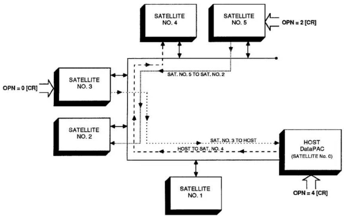
flowchart
graph TD
    A["SATELLITE NO. 1"] --> B["SATELLITE NO. 2"]
    B --> C["SATELLITE NO. 3"]
    C --> D["SATELLITE NO. 4"]
    D --> E["SATELLITE NO. 5"]
    E --> F["HOST DataPAC (SATELLITE No. 0)"]
    F --> G["OPN = 4 [CR"]]
    C -.-> H["SAT. NO. 5 TO SAT. NO. 2"]
    B -.-> I["SAT. NO. 3 TO HOST"]
    F -.-> J["OPN = 2 [CR"]]
    style A fill:#f9f,stroke:#333
    style B fill:#f9f,stroke:#333
    style C fill:#f9f,stroke:#333
    style D fill:#f9f,stroke:#333
    style E fill:#f9f,stroke:#333
    style F fill:#f9f,stroke:#333
    style G fill:#f9f,stroke:#333
Finally, by entering a command of OPN = 0 [CR] via the keyboard of NODE No. 3 (a SATELLITE), you will arrange for NODE No. 0 (the HOST) to receive all commands entered at NODE No. 3's keyboard. ALL OF THESE VARIOUS OPEN (OPN) COMMANDS CAN BE IN EFFECT AT THE SAME TIME.
Regarding the OPN command, please note the following restrictions:
- OPN does not apply to "special key" functions of the keyboard (e.g., STEP, PROMPT, etc.).
- OPN does not apply to the OPN command itself. That is, an OPN command applied to a given NODE automatically cancels any previous OPN command in effect for that NODE.
- THE "IMPLICIT" AND "EXPLICIT" ROUTING OF A GIVEN COMMAND ARE MUTUALLY EXCLUSIVE. Thus, every command routed "explicitly" by means of an OPN command will be treated by the receiving NODE strictly as a LOCAL COMMAND—even if it is one of the "implicitly addressed" commands listed in Section c.1, above, and even if the GBL = ON [CR] command is in effect at the receiving NODE. If, for example, a command of LCT x [CR] is "explicitly" routed to a NODE to which GLOBAL CHANNEL No. x is not dedicated or to whose Model 10BD1 Satellite Slave Card that channel has not been "located," then NO RESPONSE WILL BE RETURNED TO THIS INTERROGATION.
— ALSO NOTE —
In the response to an interrogation of the "range" ("x TO y") form which has been issued to a given DataPAC SATELLITE via an OPEN (OPN) command entered at the COMPUTER INTERFACE PORT of some other NODE, each per-channel answer will be terminated by the SATELLITE'S current END-OF-TRANSMISSION TERMINATOR (EOT), and not by its OUTPUT TERMINATOR (OPT) (in many cases, however, a DataPAC's EOT and OPT will be the same—see Section 1.H.3(g) of this Guidebook).
You will normally use the OPEN (OPN) command when you want to communicate more than one standard MNEMONIC COMMAND from a given NODE to another, "remotely" located NODE. When you need to communicate only one command to a "remote" DataPAC NODE (HOST or SATELLITE), you can use the the NODE (NOD) command, without first having to "open" a command route (see below).
If, after you have "opened" a command route between two NODES by an OPN = n [CR] command, you wish to return the command source in question (keyboard, COMPUTER INTERFACE PORT, or ACI PORT) to "local" operation, you should command
$$ \mathbf {O P N} = \text { LOC } [ \mathbf {C R} ] $$
The effect is to cancel the "explicit" routing of GLOBAL COMMANDS specified by the previous OPN = n [CR] command.
By asking
OPN [CR]
of a given NODE, you can learn the SATELLITE NUMBER of the NODE to which GLOBAL COMMANDS are currently being routed from the command source through which this interrogation is entered. If no command route has been "opened" from the original NODE, the response to this interrogation will be LOC.
b. ROUTING A SINGLE COMMAND BETWEEN ANY TWO DATAPAC NODES: NOD COMMAND
The NODE (NOD) command serves as a "one-line" OPEN (OPN) command. It lets you route a single MNEMONIC COMMAND directly between any two DataPAC NODES, once only, without having first to "open" the command route in question by means of an OPEN (OPN) command (above). IT DOES NOT WORK WITH OPERATOR CONSOLE SATELLITES.
Thus, to cause DataPAC NODE No. n to receive the MNEMONIC COMMAND represented by the ASCII STRING "\$," at any time during normal operation, you need only enter the following command at any other DataPAC NODE, via keyboard, COMPUTER INTERFACE PORT, or optional AUXILIARY COMPUTER INTERFACE PORT:
NOD n, \$ [CR]
"\" can consist of up to 80 ASCII characters, literally stating the single command to be transmitted to NODE No. n. (If the command "\" is a SETUP COMMAND, then NODE No. n's EEPROM Switch must, of course, be ON in order for the command to be effective.)
NOTE THAT THE RESTRICTIONS GIVEN ABOVE WITH REGARD TO THE OPEN (OPN) COMMAND APPLY IN GENERAL TO THE NODE (NOD) COMMAND.
—ALSO NOTE—
The OPN = LOC [CR] command must be in effect at the DataPAC NODE where the NODE (NOD) command is entered (see Section 5.a, above). That is, if a DataPAC NODE is presently "opened" to another network NODE, a NOD command applied to that DataPAC will have no effect.
3.B.3 Satellite Network Systems
6. COMMUNICATIONS DIAGNOSIS
a. REQUESTING ERROR LOG: SEL COMMAND
To request the "ERROR LOG" kept by the Model 10BD4 for any given SATELLITE No. n, you can apply the following SATELLITE ERROR LOG (SEL) command to the HOST, via the HOST's COMPUTER INTERFACE PORT or optional AUXILIARY COMPUTER INTERFACE PORT (it cannot be entered through the keyboard):
SEL n [CR]
A SATELLITE'S "ERROR LOG" consists of five numbers, and so the response to the above SEL command will be an output of
A, B, C, D, E
where
"A" is the number of TIMEOUT ERRORS detected for the SATELLITE since the last application of the RESET ERROR LOG (REL) command (below). A TIMEOUT ERROR occurs when a SATELLITE is not answering an interrogation by the 10BD4.
"B" is the number of "CHECKSUM" ERRORS detected by the 10BD4 since the last REL command (see Section a.1, above, for a brief description of the "CHECKSUM" procedure).
"C" will always read "0" (ZERO); THIS COUNTER IS NOT USED AT PRESENT.
"D" is the "SLOW CYCLE COUNTER." It represents the total number of 10BD4 scan cycles that have taken place since the last REL command, divided by 30,000.
"E" is the "CYCLE COUNTER." It represents the total number of 10BD4 scan cycles that have taken place since the last REL command, counted by "1's."
To request the "ERROR LOG" for ALL SATELLITES, command
SEL [CR]
To request the "ERROR LOG" for SATELLITE No. n only, command
SEL n [CR]
-and to request it for all SATELLITES from SATELLITE No. n to and including SATELLITE No. m, command
SEL n TO m [CR]
b. RESETTING ERROR LOG: REL COMMAND
To reset to zero all "ERROR-LOG" entries in the Model 10BD4 (for ALL SATELLITES), apply the following RESET ERROR LOG (REL) command to the HOST:
REL [CR]
To reset to zero all "ERROR-LOG" entries for SATELLITE No. n only, command
REL n [CR]
-and to do so for all SATELLITES from SATELLITE No. n to and including SATELLITE No. m, command
REL n TO m [CR]
TO ADD ONE OR MORE DATAPACS AT THE END OF AN EXISTING NETWORK CHAIN, you need only assign the next available SATELLITE NUMBER(S) in sequence, via the ASSIGN SATELLITE NUMBER (ASN) command (Section b.2), and follow the other DataPAC SATELLITE setup procedures given in Section b.
HOWEVER, IN ORDER TO CHANGE A DATAPAC SATELLITE'S or the HOST'S DataPAC's "GLOBAL CHANNEL RANGE" (defined by the corresponding SATELLITE (SAT) command, Section b.5.b) you must proceed as follows:
CAUTION!
ALL RELEVANT CHANNEL CALIBRATION IS LOST WHEN THE FOLLOWING PROCEDURE IS PERFORMED. THEREFORE, CHANGES OF THIS TYPE ARE NOT RECOMMENDED. Careful planning prior to setup of the SATELLITE NETWORK can reduce the probability that a change of this type will be required.
In particular, you may wish, during initial setup, to add a number of DOWNLOAD PSEUDOCHANNELS ("TYPE D0") to the end of each SATELLITE SCAN RANGE. This will allow for future expansion within each SATELLITE DataPAC and will reduce the likelihood of losing system calibration due to reconfiguration.
- Apply a command of SAT n = N/A [CR] * to the HOST DataPAC for every SATELLITE in the network.
- Reset all channels in the HOST DATAPAC's original "SAT-defined" range (Channel Nos. x through y) by applying a command of RST x TO y [CR] * to the HOST.
- Reset all channels of each "B-SIZED" DataPAC SATELLITE'S original "SAT-defined" range (Channel Nos. x through y) by applying a command of RST x TO y [CR] * to that SATELLITE.
- "Retype" to "55" all channels in the HOST DATAPAC's original "SAT-defined" range (Channel Nos. x through y) by applying a command of TYP x TO y = 55 [CR] * to the HOST.
- "Retype" to "55" all channels of each "B-SIZED" DataPAC SATELLITE'S original "SAT-defined" range (Channel Nos. x through y) by applying a command of TYP x TO y = 55 [CR] * to that SATELLITE.
- For the HOST DataPAC and every "B-SIZED" DataPAC SATELLITE, reconfigure and, if necessary, recalibrate all "local" channels that were reset by the above steps.
- Repeat the relevant "SATELLITE NETWORK SETUP" procedures given in Section 3.B.3.b., entering the new SAT ranges.
Similarly, TO CHANGE A DATAPAC SATELLITE'S or the HOST'S DataPAC's "GLOBAL BIT-GROUP RANGE" (defined by the corresponding SATELLITE SYSTEM BITS (SSB) command, Section b.6.a), you must
- Apply a command of SSB n = N/A [CR] * to the HOST DataPAC for every SATELLITE in the network.
- "Resource" the bits of all "local" BIT GROUPS that were reset by the above step.
- Repeat the relevant "SATELLITE NETWORK SETUP" procedures given in Section 3.B.3.b., entering the new SSB ranges.
Section 3.B.4
Digital "History" Recording
and Playback:
Model 10BDR64 "History" Card
and Accessories

DAYTRONIC
System 10 Guidebook
PLEASE NOTE
-
The new Models 10BHM128A, 10BHM256A, 10BHM384A, and 10BSPCA are functionally identical to the Models 10BHM128, 10BHM256, 10BHM384, and 10BSPC, respectively. Everything said in this manual about these older models applies equally to the corresponding new "A" versions.
-
The new Model 10BHDM384 High Density History Memory Card or Model 10BSPC384 High Density History SPC Option Card may be used alone with the 10BDR64 History Card to provide nonvolatile (battery-backed) storage for up to 384K individual data recordings. With these high-density cards, it is no longer necessary to also install the models 10BHM128(A) and 10BHM256(A) to obtain this amount of memory. The 10BSPC384 performs all the statistical analysis functions described in this manual for the 10BSPC.
1. THE HISTORY CARD
The purpose of the Model 10BDR64 History Card is to make, store, and output digital recordings of numerical and logic data acquired by a "B-sized" DataPAC (10K6, 10K7, 10K8, etc.).
You can instruct any one of the History Card's four independent RAM recorders to automatically record a predefined list of randomly selected DATA CHANNELS and LOGIC BITS. Recording can be at preset time intervals, or can be triggered by a specific combination of system logic, limit, and/or time-interval conditions. Similar conditions can also be specified for halting and restarting each recorder.
Special outputting commands let you transmit to an external computer, printer, or CRT display—via the DataPAC's COMPUTER INTERFACE PORT—all or part of the data recordings made by one of the four recorders since it was last interrogated, or an expandable "history window" consisting of a selected range of recordings made, if desired, both before and after occurrence of a halt-triggering condition. The latter capability lets you review the specific "data history" associated with, say, a critical limit violation or process shut-down. You can select variables to appear in a recorder's output (such as time, date, serial number, etc.), and the order in which these variables are to be transmitted.
The History Card lets you play back as a live data channel the data last recorded for any given system channel or the data recorded for that channel at a specified time in the past. When a Model 10BSPC History SPC Option Card is present, you can also play back the lowest and highest values recorded for a given DATA CHANNEL since a given recording in the past, and the continuous average value for the data reported by the channel over the same time period. "Statistical" playback functions provided by the Model 10BSPC also include X-BAR and RANGE, automatically calculated over successive "sampling" periods for a given channel. These and other playback features discussed in Section d.8, below, greatly facilitate rate-of-change computations, statistical display of process data, and other operations involving rapid analysis of "historical" data sets. You can, for example, easily arrange for simultaneous video display, on the same CRT page, of a set of "playback channels" and of the corresponding "live" data values.
Through a special "time search" function, it is possible to quickly review the values recorded by a given 10BDR64 recorder for one or a set of DATA CHANNELS over a period of time. You can also "replay" all data for a given recorder's " playback" channels, from the "oldest" to the "newest," using a variable time scale. This permits "slow motion" playback of all data recorded during a fast event, or a fast review of all data recorded for a test or process of long duration.
Playback of system BIT GROUPS is also possible, using specially set up BINARY "CONVERSION" CHANNELS.
2. "FRAMES" AND "DEPTH"
All of the DATA-CHANNEL and LOGIC-BIT readings recorded by one of the History Card's recorders at a given instant of time constitute a FRAME within that recorder's "history" memory. In other words, each FRAME corresponds to a single, instantaneous RECORDING OF DATA for all channels and bits that have been entered in the given recorder's LIST. Every FRAME can also include the date of recording, if so specified by the initial LIST (LST) command, as explained in Section d.3, below.
A sequence of FRAMES within a given recorder thus corresponds to a time-correlated sequence of separate recordings of the same set of selected process variables (channels and bits). A useful analogy, as shown in Fig. 3.B.4.1, is that of a strip of movie film, each FRAME of which depicts an instantaneous state of the same continuously changing scene.
Fig. 3.B.4.1. "Frames" of Recorded Data (for a Given History Card Recorder)
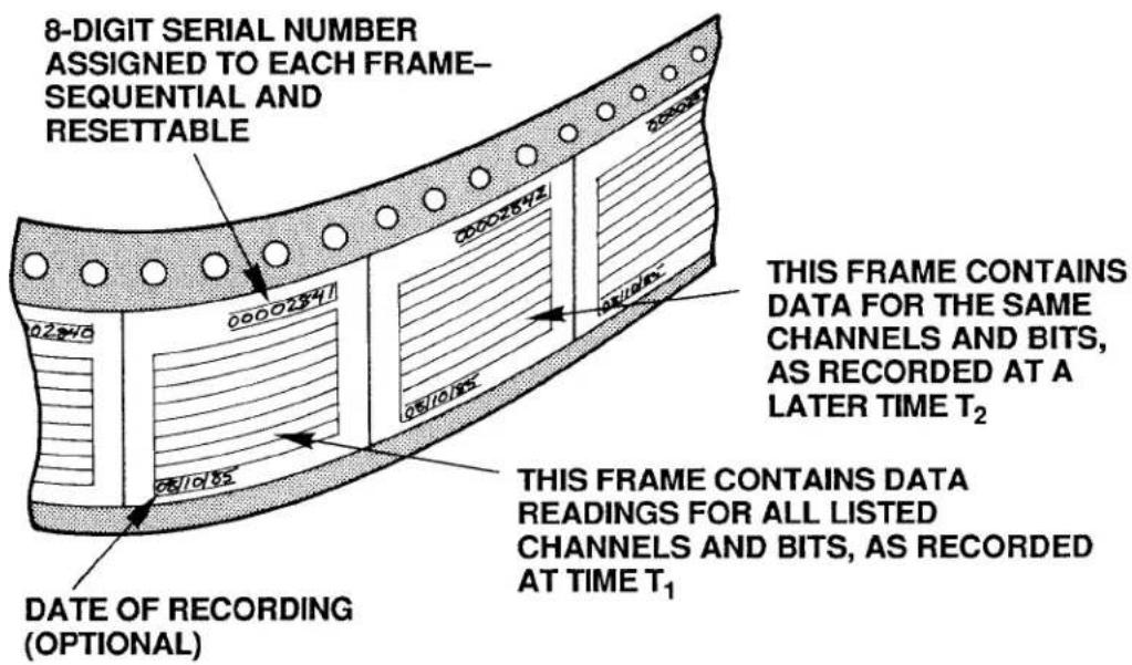
One important difference, however, between the sequence of FRAMES for a History Card recorder and for a movie film is that the time increment between successive movie FRAMES is constant, whereas the time that separates any two successive History Card FRAMES in a sequence may or may not be constant, depending on how you have set up the recording process. Thus, for example, you can instruct a History Card recorder to make recordings at precisely regular time intervals, or you can make it record only upon occurrence of a prespecified combination of system logic, limit, and/or time-interval conditions (this is explained under the STORE (STO) command, Section d.5, below).
Every FRAME of data within a recorder's memory has an 8-digit SERIAL NUMBER, for the purpose of relating it chronologically to other FRAMES in the recorder. This number provides a means of verifying not only the precise sequence of multiple recordings (FRAMES), but also the completeness of such a sequence. It can be used to correlate a given FRAME with an actual measured entity, like an individual part on production line or a measured process at a particular moment of time. SERIAL-NUMBER resetting is discussed in Section e.3, below.
The DEPTH of a given recorder refers to its FRAME capacity; the number of FRAMES of data it can hold is its "depth of storage." This is a variable quantity for each recorder and is defined by the user via the DEPTH (DPT) command, described in Section d.4. In terms of the movie-film analogy, the DEPTH is simply the number of FRAMES on the film strip, which is of course proportional to the total length of the strip.
To better conceptualize the situation, however, we need to add to our analogy an element that represents the actual recording process. Let us therefore suppose that our movie film consists initially of "blank" FRAMES. As the film is advanced (at either a constant or variable rate), each blank FRAME will successively pass in front of some kind of "imprinting device." This device will "write" upon that FRAME the data readings reported by all listed channels and bits at that instant of time. The situation is illustrated in Fig. 3.B.4.2. Note that the farther a particular "written" FRAME is from the imprinting device, the older in time is the data it contains.
Fig. 3.B.4.2. "Writing" of Data on Recorder Frames
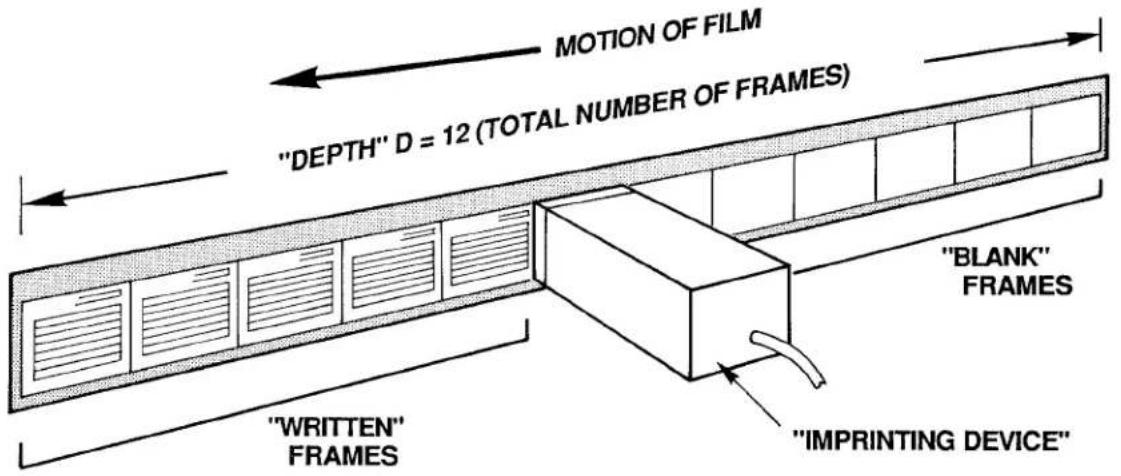
When all of the initially blank FRAMES have been "written" upon—that is, when the recorder's total DEPTH has been reached—then any subsequent recording of data automatically overwrites the oldest FRAME in that recorder's memory. To complete our picture, therefore, we must join the first and final FRAMES of our film, to create a circular band of FRAMES, continuously revolving in time. Now, each time a "written" FRAME passes by the imprinting device, it will be erased and then "rewritten" with up-to-date values for all of its listed channels and bits. See Fig. 3.B.4.3.
Fig. 3.B.4.3. Circular "Film" Allows "Rewriting" of Frames
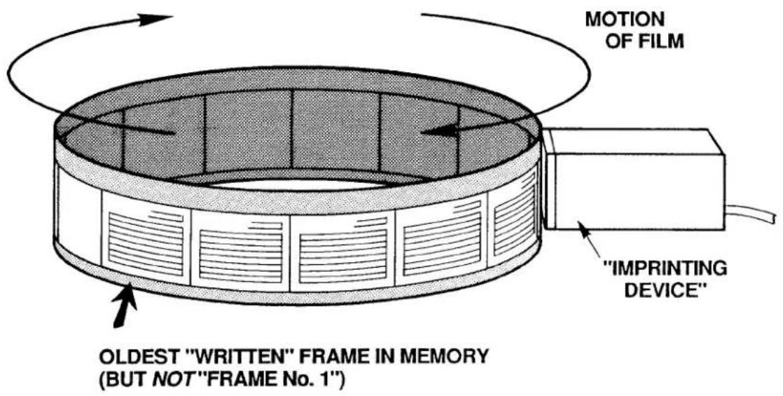
Keep in mind that we cannot now speak of an absolutely "first" or "last" FRAME in the recorder's memory (as we will see in Section e.7, below, when we assign actual "Frame Numbers," these numbers will always be relative to a predefined "halt-triggering" event). We can meaningfully speak, however, of the oldest ("written") FRAME in memory, since each FRAME corresponds to a particular time of recording.
3. HISTORY CARD STATUS INDICATORS
The History Card has eight front-panel STATUS INDICATORS. The top two are red; the lower six are green.
RAM ERROR
When this light is ON (and the CONFIG ERROR light is OFF), it means that the routine automatic self-diagnosis performed by the system on every powerup has failed to find adequate working RAM, or that a nonrecoverable hardware condition exists that prevents normal working operation of the History Card. If the indicator continues to light up as you recycle power several times, your only course of action is to replace your present History Card with another one.
CONFIG ERROR
When this light is ON, it means that the current total "history memory" is not sufficient for the present configuration of the History Card's four recorders (see Section b, below). This will occur when failure of the RAM itself has been detected during the routine automatic self-diagnosis performed by the system on every powerup, or, more likely, when a portion of the total history memory has somehow been removed since the last recorder configuration was established (e.g., a Model 10BHM128, 10BHM256, or 10BHM384 History Memory Option Card has been disconnected).
SET UP MODE
When this light is ON, it means that the History Card is in SETUP MODE. It will go OFF when the card is placed in RECORD MODE.
MNE
When this light is ON, it means that the DataPAC has received through its keyboard or COMPUTER INTERFACE PORT a valid MNEMONIC COMMAND relating to the History Card, or that an EXECUTE (EXU) or COMMAND (CMD) sequence has been triggered that contains such a command (see Section 2.K of this Guidebook).
REC 1, REC 2, REC 3, REC 4
Each recorder's individual REC indicator will light when that recorder first begins recording. It will remain lit to indicate that a recording has been made by that recorder. It will go OFF when recording stops because a HALT (HLT) condition has occurred, or whenever the recorder's memory is cleared upon entry of a HISTORY CLEAR (HCL), NONVOLATILE HISTORY (NVH), LIST (LST), or DEPTH (DPT) command (see Section b.4, below).
PLEASE NOTE
On powerup of the DataPAC, the History Card's Status Indicators may or may not go on momentarily. If they fail to light on powerup, it should not be taken as an indication that the card is malfunctioning. What should be observed on powerup is the SETUP MODE indicator blinking at a rate of approximately 1 second for every 10K of system "history memory," which is all memory resident on the History Card and on any and all installed History Memory Option Cards (Models 10BHM128, 10BHM256, and 10BHM384)—see Section 3.B.4.b.
1. CALCULATING RECORDER MEMORY VOLUME
The History Card's normal capacity is 32000 scaled data readings. The portion of this total "history memory" that will be allocated to each of the card's four RAM recorders is dependent on the size of that recorder's specified LIST of variables to be included in each FRAME of data, multiplied by the specified DEPTH (the total number of FRAMES to be recorded).
To determine a given recorder's "LIST size" (L),
a. Add the NUMBER OF "LISTED" CHANNELS and the NUMBER OF "LISTED" SYSTEM BIT GROUPS (see Section d.3 for details on LIST (LST) variables).
b. Add to this sum either "4" (if the DATE is not included in the LIST) or "6" (if the DATE is included).
C. Round up the resultant sum to the next integral multiple of 8.
To obtain the recorder's required memory volume (V), multiply the recorder's LIST size (L) by its DEPTH (D):
$$ \mathbf {V} = \mathbf {L} \times \mathbf {D} $$
For example, suppose that the LIST you have entered for Recorder No. 1 includes 28 selected DATA CHANNELS and 3 selected SYSTEM BIT GROUPS, and also specifies the recording of the system date. Then the LIST size L for this recorder equals 28 + 3 + 6 , or 37, rounded to the next higher multiple of 8, which is 40. If the DEPTH of Recorder No. 1 has been set at, say, 150, then the memory required by the recorder (in its presently specified LIST/DEPTH configuration) is 40 × 150 = 6000 readings.
Naturally, the sum of the four individual recorder memories cannot exceed the total "history memory" of the system (this is 32K readings, if the History Card is used without the optional memory extension discussed in the next section). If it happens that a recorder does not have sufficient memory to make as many recordings of a specified LIST as are called for by its specified DEPTH, then the system will automatically adjust the DEPTH of the recorder in question and also the DEPTH of every higher-numbered recorder, in order to produce an allowable recorder memory volume sufficient for the entered LIST. Lower-numbered recorders are thus given priority for memory "space."
NOTE
If a given recorder is not being used, its DEPTH should be set to "0" via the DEPTH (DPT) command (see Section d.4, below). This will allow allocation of its history memory to the remaining active recorders.
2. OPTIONAL EXTENSION OF HISTORY MEMORY: MODELS 10BHM128, 10BHM256, 10BHM384, AND 10BSPC
When the sum of the required individual recorder memories exceeds 32K readings, you may expand your total history memory by means of one or more Model "10BHM" History Memory Option Cards (10BHM128, 10BHM256, and 10BHM384). Each card provides additional history memory of up to 128K readings, according to the following sequence:
a. For up to 128K readings in addition to the History Card—or for a total nonvolatile memory of 128K readings (see below)—the Model 10BHM128 is required.
b. For up to 256K readings in addition to the History Card—or for a total nonvolatile memory of 256K readings—both the Model 10BHM128 and the Model 10BHM256 are required.
c. For up to 384K readings in addition to the History Card—or for a total nonvolatile memory of 384K readings—all three "10BHM" Cards are required: Model 10BHM128, 10BHM256, and 10BHM384.*
NOTE: The Model 10BSPC History SPC Option Card (discussed in Section d.8(d), below) also acts as a Model 10BHM128 History Memory Option Card. Thus, if a total additional or nonvolatile memory of 128K readings is desired, a Model 10BSPC alone will suffice; if up to 256K additional or nonvolatile readings are desired, a Model 10BHM256 can be used along with the 10BSPC; if up to 384K additional or nonvolatile readings are desired, both the Model 10BHM256 and the Model 10BHM384 can be used with the 10BSPC.*
All additional memory, as well as the History Card's original 32K readings will remain volatile as long as the NONVOLATILE HISTORY (NVH) command is not in effect (see below). The contents of such memory will be lost upon loss of system primary power. For installation of "History Option" Cards, see Section c, below.
3. INITIATING NONVOLATILE HISTORY MEMORY: NVH COMMAND
The Model "10BHM" History Memory Option Cards and/or Model 10BSPC History SPC Option Card also permit nonvolatile (battery-backed-up) storage of all system history recordings. When "nonvolatile history" is in effect, however, the History Card's original 32K memory is no longer available to the system.
To activate the nonvolatile history memory of any and all installed "History Option" Cards, you must be in SETUP MODE (as explained in Section d.2, below), and command
NVH [CR] \*
The application of this command physically erases all current history memory in the system, as explained in the following section. All subsequent data recordings will be stored in nonvolatile memory on the installed Model "10BHM" and/or 10BSPC Card(s) only.
Note also that the NVH [CR] * command must be applied whenever a Model "10BHM" or 10BSPC Card is added to or removed from the system.
To revert to volatile history memory, including the History Card's original 32K readings, enter SETUP MODE and command
$$ \mathbf {N V H} = \mathbf {N} / \mathbf {A} [ \mathbf {C R} ] ^ {*} $$
4. "CLEARING" AND "ERASING" HISTORY MEMORY
a. THE HISTORY CLEAR (HCL) COMMAND
The HISTORY CLEAR (HCL) command may be used to "clear" all recordings contained in a given recorder or range of recorders, without affecting any other recorder parameters. Being a
3.B.4 Digital "History" Recording and Playback
"RUN-TIME" COMMAND, it may be applied at any time during normal operation (i.e., while the History Card is in RECORD MODE), without having to turn on the EEPROM Switch. Its effect is to make inaccessible all current data recordings for the specified recorder(s), but not to physically erase this data.
Thus, to clear the history memory of Recorder No. n only, simply command
HCL n [CR]
-and to clear Recorder Nos. n through m, command
HCL n TO m [CR]
b. OTHER MEMORY-CLEARING COMMANDS: LST AND DPT COMMANDS
The LIST (LST) and DEPTH (DPT) commands will also have the effect of "clearing" one, some, or all History Card recorders—but only when the History Card is in SETUP MODE (see Section d.2, below) and the EEPROM Switch is ON.
Thus, by specifying a new LIST (LST) or DEPTH (DPT) for Recorder No. n (see Sections d.3 and d.4, respectively), you will clear not only Recorder No. n, but also all higher-numbered recorders. If, for example, you modify the LIST statement for Recorder No. 2, then Recorder Nos. 2, 3, and 4 will be completely cleared.
C. "TRUE ERASURE" OF HISTORY MEMORY: NVH COMMAND
In accordance with high-security requirements, the "true erasure" of history-memory contents is also possible. The means of "true erasure" will depend on whether your DataPAC's history "system" is in VOLATILE or NONVOLATILE MODE.
1. "TRUE ERASURE" OF VOLATILE HISTORY MEMORY
The history "system" will be in VOLATILE MODE as long as the
NVH = N/A [CR] \*
command is in effect (see Section b.3, above). When in VOLATILE MODE, all data recordings will be automatically and "truly" erased on every powerup (but not powerdown). Therefore, to ensure "true erasure" of all history memory in this mode, simply recycle DataPAC power.
2. "TRUE ERASURE" OF NONVOLATILE HISTORY MEMORY
The history "system" will be in NONVOLATILE MODE when the
NVH [CR] \*
command is in effect. In this mode, only the history memory residing on any and all optional Model "10BHM" and/or 10BSPC cards is available for storage of history recordings.
When in NONVOLATILE MODE, you can ensure "true erasure" of all history memory by simply re-entering a command of NVH [CR]*.
Concerning this command, please note that
a. Although it is a "SETUP" COMMAND and requires that the DataPAC's EEPROM Switch be ON, it does not actually write to the EEPROM, and may therefore be applied any number of times without subjecting the EEPROM to excessive write cycles.
b. As mentioned above, if the NVH [CR] * command is entered through the DataPAC's keyboard, it is necessary to recycle power in order to make the command effective.
5. REQUESTING TOTAL HISTORY MEMORY: MEM COMMAND
A MEMORY (MEM) command of
MEM [CR]
will yield a hexadecimal number representing the total number of scaled data readings your history "system" (History Card plus any and all "History Option" Cards) is capable of storing. The answer will also indicate whether the memory is currently VOLATILE or NONVOLATILE. The possible responses to the MEM [CR] interrogation are as follows:
(MEM =) 10000H (indicates 32,000 VOLATILE readings, max.) 50000H (indicates 160,000 VOLATILE readings, max.) 90000H (indicates 288,000 VOLATILE readings, max.) D0000H (indicates 416,000 VOLATILE readings, max.)
3FE00H (indicates 128,000 NONVOLATILE readings, max.) 7FE00H (indicates 256,000 NONVOLATILE readings, max.) BFE00H (indicates 384,000 NONVOLATILE readings, max.)
ONCE A MODEL 10BDR64 HISTORY CARD HAS BEEN INSERTED IN A PARTICULAR B SLOT AND HAS BEEN SET UP BY MEANS OF THE COMMANDS GIVEN IN SECTION d, BELOW, THEN THAT CARD SHOULD NOT BE MOVED TO A DIFFERENT B SLOT AT ANY LATER TIME.
Therefore, be sure to choose a B SLOT you can permanently dedicate to a History Card, before setting up that card's recording and playback functions. Also, if you ever remove a History Card for some reason, be sure to return it to its original slot location.
If your system also contains one or more "History Option" Cards—i.e., a Model 10BSPC History SPC Option Card and/or one or more Model "10BHM" History Memory Option Cards—then you will require a special HISTORY BACKPLANE to establish the necessary connections between the History Card and the installed "History Option" Card(s). All cards will plug directly into the HISTORY BACKPLANE. There are three backplane versions, depending on whether one, two, or three "History Option" Cards are to be present (see Section b.2, above). The History Card will always occupy the right-most backplane slot, as viewed from the front of the unit; a History SPC Option Card and any and all History Memory Option Cards will be located to its immediate left (on the backplane).
When a History Card and one or more "History Option" Cards are ordered with a DataPAC, the HISTORY BACKPLANE will be installed at the factory. If you order one or more "History Option" Cards for an existing DataPAC, an appropriate HISTORY BACKPLANE will be shipped with the card(s). This you may easily install in the field (contact the factory for specific instructions). In this case, remember that the History Card should retain its original B-SLOT position, as explained above, and that a History SPC Option Card and any and all History Memory Option Cards should be located to the immediate left of the History Card (on the HISTORY BACKPLANE).
1. INTRODUCTION
Of the setup procedures discussed in this section, these four are always required:
a. ENTER SETUP MODE (Section d.2)
b. LIST VARIABLES TO BE RECORDED for each recorder (Section d.3)
c. SET RECORDER DEPTH for each recorder, if it is to be other than the factory-set value of "500" (Section d.4)
d. SPECIFY "STORE" CONDITIONS for each recorder (Section d.5)
The other procedures given below may or may not be performed, depending on the your particular recording application.
When you receive your History Card, it will have been set at the factory for the following initial setup values:
• a LIST (for all recorders) of "CHN 1 TO 10, SBG 1 TO 2"
• a DEPTH (for all recorders) of "500"
• a STORE CONDITION (for Recorder No. 1) of "INT 3"
• a STORE CONDITION (for Recorder No. 2) of "INT 6"
• a STORE CONDITION (for Recorder No. 3) of "INT 9"
• a STORE CONDITION (for Recorder No. 4) of "INT 11"
• a HALT CONDITION (for all recorders) of "N/A"
• a HALT DEPTH (for all recorders) of "1"
- an OUTPUT IMAGE (for all recorders) of "FR, DN, FT, SN"
You will modify these initial assignments as your requirements demand, using the commands discussed below.
Note that all setup commands have respective interrogative forms, whereby you can ask the system at any time for the current value of a given setup parameter (for further explanation, see Sections 1.A.3(d) and 4.B of this Guidebook).
Your first setup steps will always be
• TURN ON THE DATAPAC'S EEPROM WRITE PROTECT SWITCH.
- PLACE THE HISTORY CARD IN "SETUP MODE."
2. ENTERING SETUP MODE: SMD COMMAND
NONE OF THE COMMANDS DISCUSSED IN THIS SECTION WILL BE EFFECTIVE UNLESS THE HISTORY CARD HAS FIRST BEEN PLACED IN SETUP MODE. To do this, simply command
SMD [CR]
This command immediately stops any recording in process. The History Card's front-panel SMD indicator will light while the card is in SETUP MODE.
3. LISTING VARIABLES TO BE RECORDED: LST COMMAND
To enter the LIST of DATA CHANNELS and LOGIC BITS for Recorder No. n, command
$$ \text { LST } n = \text { CHN } x _ {1}, x _ {2}, \dots , \text { SBG } k _ {1}, k _ {2}, \dots , \text { DTE } [ \text { CR } ] ^ {*} $$
3.B.4 Digital "History" Recording and Playback
where
"n" is the recorder number (1-4);
"x" is either a single channel number or a range of channel numbers expressed in the form x TO y (where y > x); and
"k" is the RANK number of a single SYSTEM BIT GROUP (SBG) or a range of RANK numbers expressed in the form k TO I (where l > k).
Please note that
NOTE: If in changing a recorder's current LIST, you exclude one or more PLAYBACK PSEUDOCHANNELS that were included in that recorder's previous LIST, a "PSEUDOCHANNEL ERROR" will be invoked for any of these PLAYBACKS. For cancelling PLAYBACK PSEUDOCHANNEL assignments, see Section 3.B.4.d.
-
A RECORDER'S "LIST," AS DEFINED BY THE ABOVE LST COMMAND, CAN TAKE UP TO 78 CHARACTERS, INCLUDING COMMAS.
-
THE SEQUENCE OF DATA CHANNELS AND/OR CHANNEL RANGES (x1, x2, etc.) MUST BE ENTERED IN ASCENDING ORDER, AS MUST THE SEQUENCE OF SYSTEM BIT GROUPS AND/OR BIT-GROUP RANGES (see the example below).
-
Channel Nos. 998 (TIME) and 999 (DATE) may not be entered in the LST expression.
-
The mnemonic DTE is optional. If it is present, the current system date will be automatically included in each recorded FRAME. Note that it is necessary to include DTE in the recorder's LST expression if you want the date to be included in the recorder's output (see Section d.10, below), or if you want to set up one or more "DATE" PLAYBACK PSEUDOCHANNELS for the recorder (Section d.8(c)).
As an example of the LIST (LST) command, suppose that you want each of the recordings (or FRAMES) produced by Recorder No. 3 to contain readings for DATA CHANNEL Nos. 1, 22, 37, 38, 39, 40, 66, and 111, and for SYSTEM BIT GROUP Nos. 2, 4, and 5—plus the current system date for each recording. You will enter this command:
$$ \text { LST 3 } = \text { CHN 1,22,37 TO 40,66,111,SBG 2,4 TO 5,DTE [CR]} ^ {*} $$
4. SETTING RECORDER DEPTH: DPT
To enter the desired DEPTH for Recorder No. n, command
$$ \mathbf {D P T} \mathbf {n} = \mathbf {d} [ \mathbf {C R} ] ^ {*} $$
where "d" is an integer from 0 through 32,767. (A recorder set to a DEPTH of "0" will not record. Such a setting can therefore be used to disable a given recorder, if it is not required, thereby allocating its history memory to the remaining active recorders.)
If you want to set a range of recorders (No. n through No. m) to the same DEPTH value, you can command
$$ \text { DPT n TO m } = \text { d [CR] } ^ {*} $$
Thus, if you want to set all four recorders to a DEPTH of, say, 999, you would command
$$ D P T 1 T O 4 = 9 9 9 [ C R ] ^ {*} $$
Remember that the maximum DEPTH to which a recorder can be set will depend on the LIST that has been entered for that recorder, and on the portion of total system "history memory" available to it (see Section b.1, above).
5. SPECIFYING "STORE" CONDITIONS: STO COMMAND
a. THE STORE (STO) COMMAND
You will use the STORE (STO) command to specify the condition or logical combination of conditions the occurrence of which will cause Recorder No. n to instantly record and store a FRAME of data. These conditions may include
- the limit status of selected system DATA CHANNELS
• the logic states of selected system LOGIC BITS - the occurrence of logic-state transitions for selected system LOGIC BITS
- the passage of a specific time interval, as registered by the system clock
The general form of the STORE (STO) command is
$$ \text { STO } \mathbf {n} = \mathbf {B} [ \mathbf {C R} ] ^ {*} $$
where "n" is the Recorder Number and "B" is a string of characters representing a Boolean algebraic expression of the general form
[MNEMONIC plus CHANNEL, BIT, or INTERVAL NUMBER] [OPERATOR] [MNEMONIC plus CHANNEL, BIT, or INTERVAL NUMBER] [OPERATOR] ...
The expression "B" may contain up to 15 MNEMONIC terms and up to 14 OPERATORS. The allowable MNEMONICS are given below. The allowable OPERATORS are "*" ("AND") and "+" ("OR").
b. STO MNEMONICS
Each "MNEMONIC plus CHANNEL, BIT, or INTERVAL NUMBER" term in the STO expression refers directly to a possible "condition" of an actual system DATA CHANNEL, LOGIC BIT, or TIME INTERVAL, as follows:
- DATA-CHANNEL LIMIT STATUS: ZGT, ZLT, AND ZVO
| To specify the condition that: | Use MNEMONIC: |
| A channel's data is in "GREATER THAN" LIMIT ZONE | ZGT |
| A channel's data is NOT in "GREATER THAN" LIMIT ZONE | /ZGT |
| A channel's data is in "LESS THAN" LIMIT ZONE | ZLT |
| A channel's data is NOT in "LESS THAN" LIMIT ZONE | /ZLT |
| A channel's data is in either ZONE OF VIOLATION (i.e., outside the "BETWEEN" LIMIT ZONE) | ZVO |
| A channel's data is NOT in either ZONE OF VIOLATION | /ZVO |
For example, the term ZGT 201 means "when data for Channel No. 201 is in the 'GREATER THAN' LIMIT ZONE"; /ZVO 8 means "when Channel No. 8 does NOT lie in either the 'GREATER THAN' or 'LESS THAN' LIMIT ZONE."
3.B.4 Digital "History" Recording and Playback
Each of these MNEMONICS may refer to any "legal" DATA CHANNEL. Remember, however, that data for any channel above the TERMINATOR CHANNEL or otherwise outside the specified SCAN RANGE may not contain currently valid data (see Section 1.F of this Guidebook).
- LOGIC STATE OF SYSTEM BIT: BIT
| To specify the condition that: | Use MNEMONIC: |
| A bit is HIGH (at a Logic 1 state) | BIT |
| A bit is NOT HIGH (i.e., it is at Logic 0) | /BIT |
For example, the term BIT 66 means "when Bit No. 66 is high"; /BIT 45 means "when Bit No. 45 is low." These MNEMONICS may refer to any system LOGIC BIT (No. 0 through 999).
- LOGIC-STATE TRANSITION OF SYSTEM BIT: BGL AND BGH
| To specify the condition that: | Use MNEMONIC: |
| A bit is GOING LOW (transition from Logic 1 to Logic 0) | BGL |
| A bit is GOING HIGH (transition from Logic 0 to Logic 1) | BGH |
For example, the term BGL 134 means "when Bit No. 134 is going low"; BGH 9 means "when Bit No. 9 is going high." The MNEMONICS may refer to any system LOGIC BIT (No. 0 through 999).
- TIME INTERVAL: INT
| To specify the condition that: | Use MNEMONIC: |
| The system time-of-day clock is registering passage of a specific time interval | INT |
The allowable system "clock-time" intervals are numbered as follows:
| 0 = 10 millisec | 6 = 1 sec | 11 = 1 min |
| 1 = 20 millisec | 7 = 2 sec | 12 = 2 min |
| 2 = 50 millisec | 8 = 5 sec | 13 = 5 min |
| 3 = 0.1 sec | 9 = 10 sec | 14 = 10 min |
| 4 = 0.2 sec | 10 = 20 sec | 15 = 20 min |
| 5 = 0.5 sec |
For example, the term INT 9 is a condition that occurs every 10 seconds; technically, it means "when the system clock reads XX:XX:X0.00 (hours : minutes : integral seconds . hundredths of a second; "X" is any digit)."
NOTE
NO MORE THAN ONE "INT" TERM CAN BE INCLUDED IN A STORE (STO) EXPRESSION.
ALSO NOTE: If you need to record data at intervals longer than 20 minutes, you can make recording dependent on the transition of a given system LOGIC BIT (using the BGL or BGH MNEMONIC, above). This "trigger bit" can in turn be automatically set or reset at intervals of up to 24 hours, by including an appropriate SET BIT (BIT) command in a COMMAND (CMD) statement (see Section 2.K.3 for details).
C. EXAMPLES OF THE STORE (STO) COMMAND
REMEMBER
What the command STO n = B [CR] * actually asserts is that Recorder No. n will produce a record of all its listed channels and bits when and only when the existing states of the system conditions indicated by the MNEMONIC terms of the expression "B" are such that their logical combination, as given by the OPERATORS of that expression, yields a total "truth value" of "1."
For example, here are a few typical STORE (STO) commands:
$$ \text { STO } 1 = \text { ZLT } 1 0 + \text { ZLT } 1 1 [ \text { CR } ] ^ {*} $$
(Recorder No. 1 will record and store a FRAME when data for EITHER Channel No. 10 OR Channel No. 11 is in the "LESS THAN" LIMIT ZONE.)
$$ \text { STO 3 } = \text { BGH 689 } * \text { ZVO 72 [CR]} * $$
(Recorder No. 3 will record and store a FRAME when Bit No. 689 goes high AND a limit violation is occurring for Channel No. 72.)
$$ \text { STO } 4 = \text { BGL } 6 8 9 + \text { BGH } 1 0 1 * / \text { ZVO } 7 2 [ \text { CR } ] ^ {*} $$
(Recorder No. 4 will record and store a FRAME EITHER when Bit No. 689 goes low OR when Bit No. 101 goes high and at the same time data for Channel No. 72 lies in the "BETWEEN" LIMIT ZONE.)
$$ \text { STO } 1 = \text { INT } 5 [ \text { CR } ] ^ {*} $$
(Recorder No. 1 will record and store a FRAME every half second.)
$$ \text { STO } 2 = \text { BIT } 3 2 * \text { INT } 6 + / \text { BIT } 3 2 * \text { INT } 1 1 [ \text { CR } ] * $$
(Recorder No. 2 will record and store a FRAME every second when Bit No. 32 is high, OR every minute when this bit is low.)
To cancel the existing STO condition(s) for Recorder No. n, command
$$ \text { STO } \mathbf {n} = \mathbf {N} / \mathbf {A} [ \mathbf {C R} ] ^ {*} $$
3.B.4 Digital "History" Recording and Playback
6. SPECIFYING "HALT" CONDITIONS: HLT COMMAND
To specify the condition or logical combination of conditions the occurrence of which will cause Recorder No. n to halt the recording of data, command
$$ \mathbf {H L T} \mathbf {n} = \mathbf {B} [ \mathbf {C R} ] ^ {*} $$
Syntax for the expression "B" is the same as for the STORE (STO) command, above.
To cancel the existing halt condition(s) for Recorder No. n, command
$$ \mathrm{HLT} \mathbf {n} = \mathbf {N} / \mathbf {A} [ \mathrm{CR} ] ^ {*} $$
IMPORTANT
IF NONVOLATILE HISTORY MEMORY IS IN EFFECT (Section b.3, above), THEN A HALTED RECORDER WILL REMAIN HALTED-EVEN UPON CYCLING OF DATAPAC POWER-UNTIL APPLICATION TO THAT RECORDER OF A START FROM HALT (STH) COMMAND (see Section e.5, below).
7. SETTING HALT DEPTH: HDP COMMAND
You may sometimes want to record a specific number of FRAMES after a "halt-triggering event" has occurred. To arrange for the actual halting of Recorder No. n to be delayed accordingly, command
$$ \mathbf {H D P} \mathbf {n} = \mathbf {q} [ \mathbf {C R} ] ^ {*} $$
where "q" is the recorder's HALT DEPTH (i.e., the number of FRAMES that will be recorded following occurrence of the "halt-triggering" condition). It may be any integer from 0 through 32767. See Fig. 3.B.4.4.
"Frame Numbers" will be discussed under the HISTORY DUMP (HDU) command, Section e.7(b), below. See also the CURRENT HALT STATUS (CHS) command (Section e.4), which lets you ask for the number of FRAMES that have been recorded so far since occurrence of the "halt-triggering" condition. For restarting a halted recorder, see Section e.5.
Fig. 3.B.4.4. Assignment of Frame Numbers
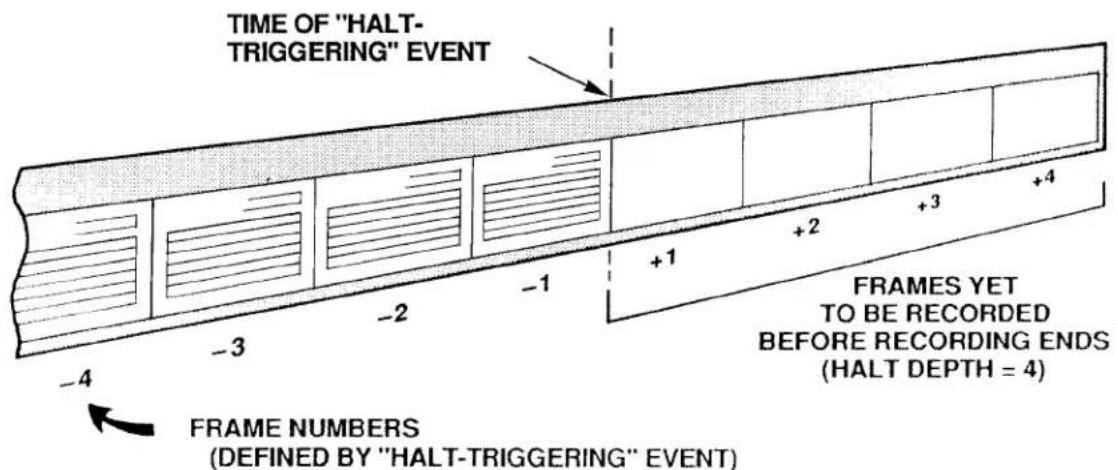
8. DEFINING PLAYBACK PSEUDOCHANNELS: PLA COMMAND
a. INTRODUCTION: "NORMAL" AND "VIDEO" PLAYBACK PSEUDOCHANNELS
The History Card's playback function makes available for direct interrogation or video display all of the readings recorded for a given system DATA CHANNEL that are currently in history memory.
The playback setup procedure involves the assignment of a PLAYBACK PSEUDOCHANNEL to every DATA CHANNEL whose past readings, as recorded by a given recorder, you wish to review. Depending on the channel number you assign it, a PLAYBACK PSEUDOCHANNEL can be either
- a "NORMAL" PLAYBACK PSEUDOCHANNEL (which can have any Channel Number from 1 through 997), or
- a VIDEO PLAYBACK PSEUDOCHANNEL (which must have a Channel Number from 1000 through 1299)
The main difference between these two types of PSEUDOCHANNELS is that, unlike "NORMAL" PSEUDOCHANNELS, VIDEO PSEUDOCHANNELS are read only by the system's video cards. They are not included in the normal scanning of system channels, and therefore the system does not "spend time" in handling them.
"NORMAL" PLAYBACK PSEUDOCHANNELS are used primarily when you wish to interrogate the system for recorded data values by means of the CHANNEL (CHN) command, or to provide limit-monitoring or analog output for playback channels.
VIDEO PLAYBACK PSEUDOCHANNELS are not interrogatable via the CHANNEL (CHN) command, but are strictly intended for CRT display of recorded data. Like all other DATA CHANNELS, they allow for the exhibition of CRT VISUAL EFFECTS. In the case of VIDEO PLAYBACK PSEUDOCHANNELS, however, such effects may be controlled only by the STATUS (STS) command (see Section 2.C.12(e)). As explained in Section c, below, a VIDEO PLAYBACK PSEUDOCHANNEL can also be set up to display a recorded FRAME's SERIAL NUMBER, TIME, or DATE.
Every VIDEO PLAYBACK PSEUDOCHANNEL will be displayed on the CRT screen within a VIDEO PLAYBACK FIELD. This variable field is to be entered in the process of composing the respective VIDEO PAGE FORMAT, as explained in Section 2.C.5(h) of this Guidebook. (The procedure for entering a VIDEO PLAYBACK FIELD is identical to that for entering a DATA FIELD, except that the channel-number entry, which is now any number from 1000 through 1299, must be preceded by an asterisk (*).)
NOTE
- The total number of "NORMAL" PLAYBACK PSEUDOCHANNELS that can be set up for a given History Card is 29 channels per recorder.
- The total number of VIDEO PLAYBACK PSEUDOCHANNELS that can be set up for a given History Card is 300 channels, regardless of the recorder(s) to which they are assigned.
- The total number of "STATISTICAL" PLAYBACKS ("NORMAL" or "VIDEO") that can be set up for a given History Card is 25 channels per recorder (these are discussed in Section d.8(d), below).
— ALSO NOTE —
WHEN YOUR SYSTEM'S HISTORY MEMORY IS IN NONVOLATILE MODE-I.E., WHEN THE NVH [CR] * COMMAND IS IN EFFECT (Section 3.B.4(b.3)-YOU MUST APPLY A RECORD MODE (RMD) COMMAND TO THE DATAPAC FOLLOWING EVERY POWERUP, IN ORDER TO ACTIVATE THE SYSTEM'S CURRENT PLAYBACKS (see Section 3.B.4(e.2), below, for details).
b. THE PLAYBACK (PLA) COMMAND AND RELATED "RUN-TIME" COMMANDS (ZUM, FRZ, RPL)
Like CALCULATE PSEUDOCHANNELS, PLAYBACK PSEUDOCHANNELS are automatically "configured" as soon as they are defined. Thus, each of the PLAYBACK (PLA) commands given below and in the following sections will have the effect of assigning a TYPE code of D9 to the channel being set up (Channel No. x).
To set up a PLAYBACK PSEUDOCHANNEL No. x to represent the data value for DATA CHANNEL No. y that was last recorded by Recorder No. n, command
$$ \text { PLA } x = \text { REC } n, \text { CHN } y [ \text { CR } ] ^ {*} $$
In this and the following PLA command, the channel number "x" can be from 1 through 997 if you are setting up a "NORMAL" PLAYBACK PSEUDOCHANNEL, or from 1000 through 1299 if it is to be a VIDEO PLAYBACK PSEUDOCHANNEL.
To set up a PLAYBACK PSEUDOCHANNEL No. x to represent the data value for DATA CHANNEL No. y that was recorded by Recorder No. n a specific number of FRAMES in the past, command
$$ \text { PLA } x = \text { REC } n, \text { CHN } y (- f) [ \text { CR } ] ^ {*} $$
Here, "f" is the SEARCH DEPTH for PLAYBACK PSEUDOCHANNEL No. x. This is the number of FRAMES "ago" at which the SEARCH FRAME is located. It is thus a measure of the "pastness" in time of the FRAME within the recorder's memory that contains the data reading of interest (see Fig. 3.B.4.5). The allowable SEARCH DEPTH (f) can be from 1 through 32767, provided that it does not exceed the total DEPTH predesignated for Recorder No. n via the DEPTH (DPT) command.
Note that, as time goes on and new recordings continue to be made, the SEARCH FRAME will "advance" accordingly, since the SEARCH DEPTH (the "pastness" of the SEARCH FRAME) will always remain constant, unless a ZOOM (ZUM), FREEZE (FRZ), or REPLAY (RPL) command is in effect.
The situation is illustrated in Fig. 3.B.4.5. The upper picture represents the state of a recorder "film strip" at a given time; the lower picture shows the same strip at a later time, after another recording has been made. With the recording of the FRAME with the SERIAL NUMBER of "7," the SEARCH FRAME automatically moves from "2" to "3," and the data reading reported by the PLAYBACK PSEUDOCHANNEL changes accordingly. The SEARCH DEPTH, however, remains a constant five FRAMES.
Several very useful "RUN-TIME" COMMANDS relate to the playback of "historical" data. By means of the ZOOM (ZUM) command you can readily alter the magnitude of the SEARCH DEPTH (and hence the current position of the SEARCH FRAME). The FREEZE (FRZ) command lets you "zoom" to a SEARCH FRAME that does not change with ongoing recordings. The REPLAY (RPL) command allows the automatic FRAME-by-FRAME reduction of a recorder's SEARCH DEPTH at a specified rate. These commands are discussed in detail in Sections e.8 and e.9, below.
Fig. 3.B.4.5. Specification of Playback "SEARCH DEPTH"
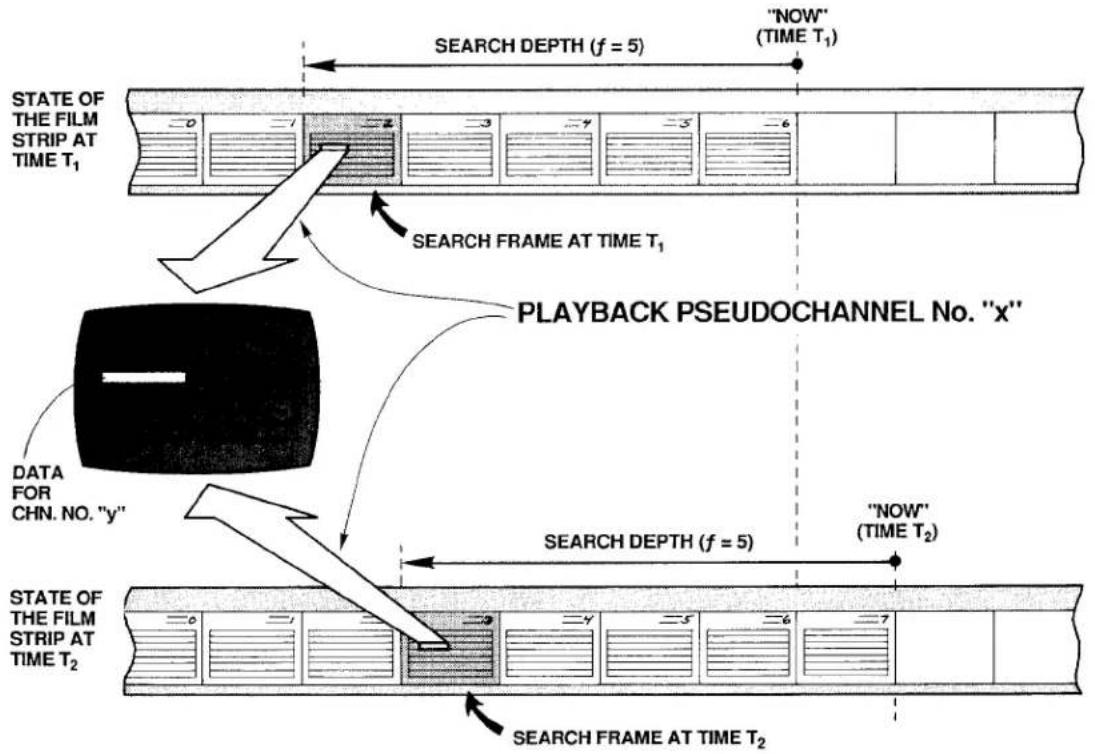
flowchart
graph TD
    A["STATE OF THE FILM STRIP AT TIME T₁"] --> B["SEARCH FRAME AT TIME T₁"]
    B --> C["PLAYBACK PSEUDOCHANNEL No. "x""]
    C --> D["DATA FOR CHN. NO. "y""]
    D --> E["SEARCH DEPTH (f = 5)"]
    E --> F[""NOW" (TIME T₁)"]
    F --> G["STATE OF THE FILM STRIP AT TIME T₂"]
    G --> H[""NOW" (TIME T₂)"]
    H --> I["SEARCH FRAME AT TIME T₂"]
The ZOOM (ZUM) command can be applied even while recording is in process, in order to rapidly review the values that have been reported by one or more DATA CHANNELS over an "historical" period of time. Specifically, you can use it to observe how all or part of the DATA CHANNELS contained in a given recorder's LIST have evolved together in time. Such "time-coherent zooming" of a whole set of channels is discussed in detail in Section e.8. For setup purposes, however, you should note here that it is useful in such cases to set up a PLAYBACK PSEUDOCHANNEL that lets you identify the current SEARCH FRAME in terms of either its SERIAL NUMBER or TIME of recording, as explained in the following section.
You can assign to the same DATA CHANNEL (No. y) more than one PLAYBACK PSEUDOCHANNEL, each with a different SEARCH DEPTH "f." This lets you display simultaneously and on the same CRT page the data values reported by Channel No. y at different times "ago." Note, however, that it is generally not a good idea to mix a channel's "live" (i.e., current) data reading with "playbacks" of its past readings on the same VIDEO PAGE FORMAT, if you intend to use the ZOOM (ZUM) command for "time search" purposes (see Section e.8).
PLEASE NOTE
The ZUM, FRZ, and RPL commands do not apply to the "STATISTICAL" PLAYBACK PSEUDOCHANNELS described in Section d.8(d), below. The application of ZUM to a given recorder or recorders will not affect any such playbacks set up for that recorder or recorders, while the application of either FRZ or RPL will actually disable any and all "STATISTICAL" PLAYBACKS for the recorder(s) in question as long as the command is in effect.
C. SPECIAL VIDEO PLAYBACKS: SERIAL NUMBER, TIME, AND DATE
To set up a VIDEO PLAYBACK PSEUDOCHANNEL to display the SERIAL NUMBER of the SEARCH FRAME, command
$$ \text { PLA } x = \text { REC } n, \text { SER } (- f) [ \text { CR } ] ^ {*} $$
where 1000 ≤ x ≤ 1299 and 1 ≤ f ≤ 32767 .
To set up a VIDEO PLAYBACK PSEUDOCHANNEL to display the TIME of the SEARCH FRAME, to the nearest second or to the nearest hundredth of a second, command, respectively
$$ \text { PLA } x = \text { REC } n, \text { TME } (- f) [ \text { CR } ] ^ {*} $$
or
$$ \text { PLA } x = \text { REC } n, \text { TMF } (- f) [ \text { CR } ] ^ {*} $$
To set up a VIDEO PLAYBACK PSEUDOCHANNEL to display the DATE of the SEARCH FRAME, command
$$ \text { PLA } x = \text { REC } n, \text { DTE } (- f) [ \text { CR } ] ^ {*} $$
Note that in order for the "DATE" PLAYBACK to be effective, it is necessary that the DTE mnemonic be included in the LIST (LST) expression for Recorder No. n (see Section d.3, above).
If the SEARCH FRAME indicator "-f)" is omitted from any of the above four PLA commands, a default value of "-1" will be assumed. That is, the playback of SERIAL NUMBER, TIME, or DATE will refer to the last recording made by Recorder No. n.
d. STATISTICAL PLAYBACKS: Model 10BSPC
The main function of the Model 10BSPC History SPC Option Card is to perform statistical analysis of data recorded by the Model 10BDR64 History Card. Enhancing the History Card's basic playback capabilities, while relieving the DataPAC's CENTRAL PROCESSOR of the required computational tasks, it is an important tool for on-line Statistical Process Control (SPC).
As explained in Section b.2, above, the 10BSPC also acts as a Model 10BHM128 History Memory Option Card, providing 128K scaled readings in addition to those of the History Card, or allowing conversion to a nonvolatile history memory of up to 128K readings. For installation of the 10BSPC, see Section c, above.
Specifically, the Model 10BSPC makes possible several special forms of the PLAYBACK (PLA) command, which may be used to set up "STATISTICAL" PLAYBACK PSEUDO-CHANNELS. Such playbacks may be either "NORMAL" or "VIDEO." No more than 25 "STATISTICAL" PLAYBACK PSEUDOCHANNELS may be set up for a given recorder.
NOTE ALSO THAT ALL VALUES REPORTED BY "STATISTICAL" PLAYBACK PSEUDO-CHANNELS ARE ROUNDED DOWN TO THE NEAREST INTEGER.
IMPORTANT
You should not set up both "STATISTICAL" and "NON-STATISTICAL" PLAYBACKS for the same recorder if you wish to apply the FREEZE (FRZ) or REPLAY (RPL) commands to that recorder. This is because the application of either of these commands to a given recorder WILL DISABLE ANY AND ALL "STATISTICAL" PLAYBACKS SET UP FOR THAT RECORDER AS LONG AS THE COMMAND IS IN EFFECT.
Application of a ZOOM (ZUM) command to a given recorder will not disable any "STATISTICAL" PLAYBACKS set up for that recorder; however, it will not affect them either. That is, it will not change the existing SEARCH DEPTH setting for any of these playbacks.
1. "CONTINUOUS" STATISTICAL PLAYBACKS: AVERAGE, MAXIMUM, AND MINIMUM
A command of
$$ \text { PLA } x = \text { REC } n, \text { AV } y (- f) [ \text { CR } ] ^ {*} $$
will set up a PLAYBACK PSEUDOCHANNEL No. x to report the continuous average value experienced by DATA CHANNEL No. y over the last "f" recordings of Recorder No. n. For this and the two following PLA commands, 1 ≤ x ≤ 997 ("NORMAL" PLAYBACK) or 1000 ≤ x ≤ 1299 ("VIDEO" PLAYBACK), and 1 ≤ f ≤ 10000 .
Similarly, you can arrange for the playback of the lowest or highest value experienced by Channel No. y over the last "f" recordings of Recorder No. n by commanding, respectively,
$$ \text { PLA } x = \text { REC } n, \text { LO } y (- f) [ \text { CR } ] ^ {*} $$
or
$$ \text { PLA } x = \text { REC } n, \text { HI } y (- f) [ \text { CR } ] ^ {*} $$
NOTE
For all "AVERAGE," "MAXIMUM," AND "MINIMUM" PLAYBACKS, the SEARCH DEPTH ("I")—i.e., the number of recorded FRAMES over which the average, maximum, or minimum of Channel No. y is continuously reported—will always remain the same. Thus, with each new recording made by Recorder No. n, the newly recorded FRAME will be added to each playback's "statistical base," while the oldest FRAME will be dropped. As mentioned above, application of the ZOOM (ZUM) command (which is normally used to modify a playback's SEARCH DEPTH while in RECORD MODE) will have no effect on any "STATISTICAL" PLAYBACK.
2. "INDUSTRY STANDARD" STATISTICAL PLAYBACKS: X-BAR AND RANGE
Unlike the above "STATISTICAL" PLAYBACKS, the "X-BAR" and "RANGE" PLAYBACKS do not operate "continuously," but on the basis of successive "sampling periods," each of which consists of the same fixed number of data recordings (1 through 25).
To set up an "X-BAR" PLAYBACK PSEUDOCHANNEL, command
$$ \text { PLA } x = \text { REC } n, X B R y (- f) [ C R ] ^ {*} $$
where "f" here defines the number of recorded FRAMES per "sampling period" (1 ≤ f ≤ 25).
Assume, for example, that we have entered an "f" of "10." As Recorder No. n is making its first ten recordings, Channel No. x will read a data value of "0." However, as soon as the recorder begins its 11th recording, Channel No. x will report the average value for Channel No. y's data over the first "sampling period" (the first 10 recordings). Channel No. x will continue to report this value until the next sampling period is finished—that is, until the next ten recordings have been made. It will then report the average for Channel No. y as computed over the second sampling period (the 11th through 20th recordings), a value which will be held until the third sampling period is finished, and so on.
The "RANGE" PLAYBACK operates in a similar fashion. It is set up by a command of
$$ \text { PLA } x = \text { REC } n, R y (- f) [ C R ] ^ {*} $$
Channel No. x will now read the absolute value of the difference between the highest and lowest values of Channel No. y over the previous sampling period (reading "0" up until the "fth" recording is finished). The maximum value that can be reported by a "RANGE" PLAYBACK PSEUDOCHANNEL is 32767. Again, 1 ≤ f ≤ 25 .
"X-BAR" and "RANGE" PLAYBACKS may be reset at any time by means of the RSP command, as described in the following section.
e. RESETTING "X-BAR" AND "RANGE" PLAYBACKS: RSP COMMAND
The RESET STATISTICAL PLAYBACK (RSP) command serves to reset all "X-BAR" and "RANGE" PLAYBACK PSEUDOCHANNELS for a given recorder or range of recorders—if, for example, a test needs to be restarted while recording is still in process.
Thus, to reset all "X-BAR" and "RANGE" PLAYBACK PSEUDOCHANNELS for Recorder No. n, command
$$ \mathsf {R S P} \mathsf {n} [ \mathsf {C R} ] $$
To reset all "X-BAR" and "RANGE" PLAYBACK PSEUDOCHANNELS for Recorder Nos. n through m, command
$$ \mathrm{RSP} \mathrm{nTOm[CR]} $$
The effect of the RSP command is to return each playback in question to its initial state ("NO RECORDINGS YET") with a data reading of "0" (zero).
f. CANCELLING PLAYBACK ASSIGNMENTS: PLA AND RST COMMANDS
To release Channel No. x from its PLAYBACK PSEUDOCHANNEL assignment (either "NORMAL" or VIDEO), in order that it may be reconfigured for some other use, command
$$ \mathbf {P L A} \mathbf {x} = \mathbf {N} / \mathbf {A} [ \mathbf {C R} ] ^ {*} $$
This command will automatically "retype" Channel No. x as "D0."
To cancel the playback assignments of all channels from Channel No. x through Channel No. y, "retyping" them all as "D0," command
$$ \mathbf {P L A} \times \mathbf {T O} \mathbf {y} = \mathbf {N} / \mathbf {A} [ \mathbf {C R} ] ^ {*} $$
If the History Card is absent, you may use a RESET (RST) command of
RST x [CR] \* or RST x TO y [CR] \*
to cancel one or a range of playbacks, "retyping" them to "D0."
Note that the "WRITE" form of the TYPE (TYP) command will never affect a PLAYBACK PSEUDOCHANNEL.
9. SETTING UP PLAYBACK OF SYSTEM BIT GROUPS: CHN, PLA, CCH, AND BIN COMMAND
Suppose that you wish to playback the state of a given BIT GROUP No. k that was recorded by Recorder No. n "f" FRAMES ago. To do so, you may use the BINARY (BIN) command, as explained in the following procedure. For a complete discussion of the BIN command, see Section 3.B.2(e) of this Guidebook.
a. You must first establish a "REAL" DATA CHANNEL (No. y) to read the BINARY value represented by the 16 bits of BIT GROUP No. k. Enter a CHANNEL (CHN) command of the form
$$ \mathbf {C H N} \mathbf {y} = \text { BIN } \mathbf {k} [ \mathbf {C R} ] ^ {*} $$
where "y" is any unused system Channel Number (0 through 997).
b. You must make sure that Channel No. y is included in the "LIST" of variables to be recorded by Recorder No. n-along with the BIT GROUP in question (No. k). See the LIST (LST) command, Section d.3, above. Also make sure that Channel No. y is within the DataPAC's current SCAN RANGE.
C. Now set up a "NORMAL" PLAYBACK PSEUDOCHANNEL (No. x) to represent the data value for Channel No. y that was recorded by Recorder No. n "f" FRAMES in the past. As explained in Section d.8, above, you would enter a PLAYBACK (PLA) command of
$$ \text { PLA } x = \text { REC } n, \text { CHN } y (- f) [ \text { CR } ] ^ {*} $$
d. You must now establish a CONVERSION CHANNEL (No. c), in order to convert the decimal value reported by PLAYBACK PSEUDOCHANNEL No. x back to a BINARY representation. Enter a BINARY (BIN) command of
$$ \mathbf {B I N} \mathbf {j} = \mathbf {C H N} \mathbf {c} [ \mathbf {C R} ] ^ {*} $$
where "j" is any BIT GROUP other than "k." BIT GROUP No. j will now be continuously configured by the digitally converted data it receives from CONVERSION CHANNEL No. c.
e. Finally, assign PLAYBACK PSEUDOCHANNEL No. x to be the "source" for CONVERSION CHANNEL No. c by entering a CONVERSION CHANNEL (CCH) command of
$$ \mathbf {C C H} \mathbf {c} = \mathbf {x} [ \mathbf {C R} ] ^ {*} $$
As a result of the above steps, BIT GROUP No. j will continuously reflect the logic-state configuration of BIT GROUP No. k that existed "f" FRAMES ago, and may be interrogated by a SET BIT (BIT) or HEXADECIMAL (HEX) command (see Section 2.H.2(c) of this Guidebook). The playback "time search" and "replay" features described in Sections e.8 and e.9, below, may also be employed with regard to the "BIT GROUP" PLAYBACK PSEUDOCHANNEL No. x.
3.B.4 Digital "History" Recording and Playback
10. FORMATTING RECORDER OUTPUTS: IMA COMMAND
The OUTPUT IMAGE (IMA) command lets you select the variables you want to appear in each line of output produced by Recorder No. n in response to an EMPTY (EMP) or HISTORY DUMP (HDU) command, and the order in which these variables are to be transmitted. Each line of output corresponds to a FRAME of recorded data. The EMP and HDU commands are treated in detail in Sections e.6 and e.7, below.
The IMA command has this general form:
$$ \text { IMA } n = v _ {1}, v _ {2}, \dots , v _ {n} [ C R ] ^ {*} $$
The successive "v" terms are MNEMONICS for selected output variables from the following list:
FR FRAME NUMBER (see Section e.7(a), below). In the output, all frames will be preceded by FRA.
DN DATA NUMBER (either Channel No. or System Bit Group No.), followed by appropriate DATA. Thus, each DATA CHANNEL included in the recorder's initial LIST will be transmitted as [CHN. NO.][DATA]. Each listed SYSTEM BIT GROUP (SBG) will be transmitted as [SBG NO.][DATA], with the symbol # preceding the Bit Group Number. DATA for each listed BIT GROUP will be represented by a 4-character HEXADECIMAL WORD, followed by the letter H.
DV DATA ONLY (no Channel No. or System Bit Group No. "echo").
DT DATE on which the FRAME was recorded, with a format of XXXXXX (month, day, and year). See Note d, below.
FT FRACTIONAL TIME at which the FRAME was recorded, with a format of XXXXXX.XX (hours, minutes, and seconds—as determined by the TME = t [CR]* command—plus hundredths of a second, not settable by the user).
TM INTEGRAL TIME at which the FRAME was recorded, with a format of XXXXXX (hours, minutes, and seconds—as determined by the TME = t [CR]* command).
SN SERIAL NUMBER of the FRAME.
Concerning the above MNEMONICS, you should note the following:
a. MNEMONICS may not be repeated in the IMA expression.
b. MNEMONICS may be entered in any desired order in the IMA expression.
c. DN and DV are mutually exclusive, as are FT and TM. Thus, you can select only one output format for DATA and only one format for TIME.
d. DT will not be included in the recorder's output unless DTE is also present in the recorder's LIST (see Section d.3, above).
e. If any of the above MNEMONICS is omitted from the IMA expression, the corresponding variable will not appear in the output.
f. Your History Card has been factory-set for an initial "image" of FR, DN, FT, SN.
As an example of the OUTPUT IMAGE (IMA) command, suppose that you want to indicate for Recorder No. 2 a line-output "image" that looks, in general, like this:
[SERIAL NO.],[INTEGRAL TIME],[DATE],[CHN. NO.],[DATA],[CHN. NO.],[DATA],...,[SBG NO.],[DATA],[SBG NO.],[DATA],...[CR][LF]
The appropriate command would be
$$ \text { IMA 2 } = \text { SN,TM,DT,DN[CR]} ^ {*} $$
Fig. 3.B.4.6 represents an actual printout of seven FRAMES of data, recorded at 30-second intervals, as formatted by the above IMA command. In this case, the recorder's LIST consists of Channel Nos. 1, 3, 4, and 5; System Bit Group Nos. 7 and 8; and DATE-as specified by a command of
$$ \text { LST } 2 = \text { CHN } 1, 3 \text { TO } 5, \text { SBG } 7 \text { TO } 8, \text { DTE } [ \text { CR } ] ^ {*} $$
Fig. 3.B.4.6.
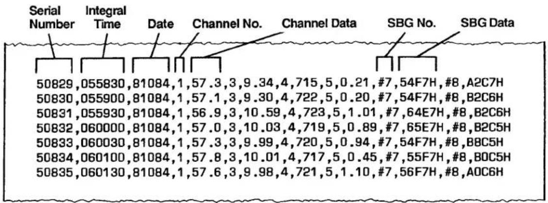
Or suppose you want an output line for Recorder No. 2 of the general form
[DATA], [DATA], [DATA], ..., [FRACTIONAL TIME], [FRAME NO.][CR][LF]
You would then command
$$ \text { IMA } 2 = \text { DV,FT,FR[CR]} ^ {*} $$
Fig. 3.B.4.7 shows a printout of six FRAMES (Nos. -4 through (+)2), recorded at half-second intervals, as formatted by this IMA command. Here, the recorder's LIST consists of five DATA CHANNELS and two BIT GROUPS.
Note that an OUTPUT TERMINATOR of [CR][LF] has been assumed in these examples. To designate different END-OF-LINE terminating characters, you may use the OUTPUT TERMINATOR (OPT) command (see Section 1.H.3(g) of this Guidebook).
Fig. 3.B.4.7
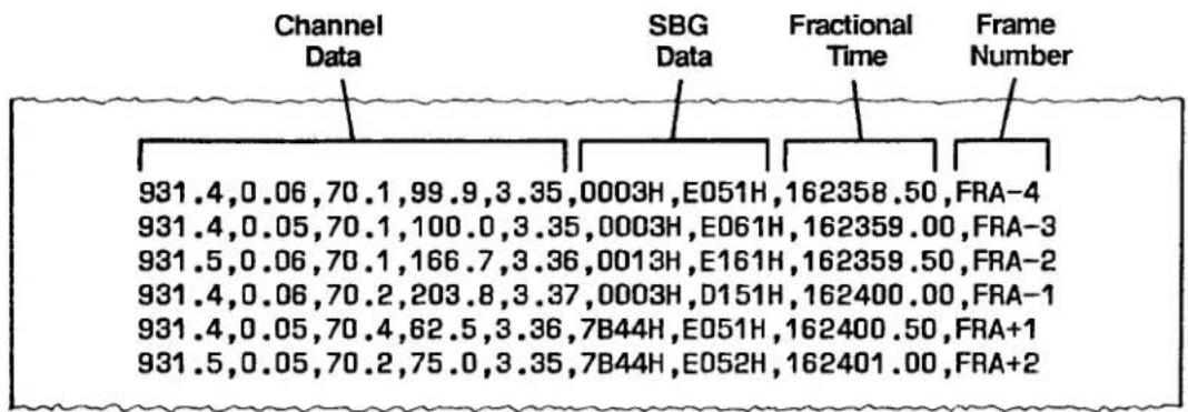
1. INTRODUCTION
The commands discussed in this section are "RUN-TIME" interrogative or imperative commands, and may therefore be applied, when appropriate, during the History Card's normal recording and playback operation.
As soon as you have completed all setup procedures dictated by your History Card's specific application, you should
• TURN OFF THE DATAPAC'S EEPROM WRITE PROTECT SWITCH.
- PLACE THE HISTORY CARD IN "RECORD MODE."
2. ENTERING RECORD MODE: RMD COMMAND
a. THE RECORD MODE (RMD) COMMAND
To exit SETUP MODE, thus making each of the History Card's recorders ready to record data, command
RMD [CR]
This command inhibits further entry or modification of recorder setup values. If you need to change setup values at any later time, you must re-enter SETUP MODE via the SMD command (Section d.2, above).
PLEASE NOTE: If the DataPAC's Channel 998 ("TIME") has been "locked" by means of a LOK [CR] command either before or after the History Card was placed in SETUP MODE, then the History Card WILL NOT GO INTO RECORD MODE UPON ENTRY OF THE RMD COMMAND. THE TIME CHANNEL MUST BE "UNLOCKED" IN ORDER FOR THE HISTORY CARD TO ENTER RECORD MODE.
b. AUTOMATIC ENTRY OF RMD FOLLOWING POWERUP IN "NONVOLATILE HISTORY" MODE
The two following procedures show how you can arrange to enter the RMD command automatically, in the event that DataPAC power is recycled during unattended operation. The method you choose will depend on your available system resources.
1. USE OF THE CONDITIONAL (CDL) AND COMMAND (CMD) COMMANDS
(For a full discussion of the CDL and CMD commands, see Section 2.K.3 of this Guidebook.)
a. Turn ON the DataPAC's EEPROM Switch and enter a command of
$$ \mathbf {C D L} \mathbf {q} = / B I T r \cdot I N T 6 [ C R ] ^ {*} $$
where "q" is any currently unused CONDITIONAL BIT and "r" is any currently unused LOGIC BIT (Bit No. r should have a LOGIC SOURCE of "EXT, NON"-see Section 2.H.2).
b. Then enter a command of
$$ \text { CMD } q = \text { RMD }: \text { BIT } r = 1 [ \text { CR } ] ^ {*} $$
3.B.4 Digital "History" Recording and Playback
As a result of these commands, the RMD command will be applied automatically fifteen seconds after every powerup (CDL-triggered sequences are always delayed by fifteen seconds after powerup).
2. USE OF THE EXECUTE (EXU) COMMAND
(For a full discussion of the EXU command, see Section 2.K.2 of this Guidebook.)
a. Select a currently unused Channel No. x which is included in the DataPAC's present SCAN RANGE.
b. Assign a "TYPE" code of "D2" (INCREMENTAL TIMER PSEUDOCHANNEL) to Channel No. x by turning ON the DataPAC's EEPROM Switch and entering a command of
$$ \text { TYP } x = \text { D2 } [ \text { CR } ] ^ {*} $$
c. Set a high limit value of "15" for Channel No. x by commanding
$$ \mathrm{HIL} x = 1 5 [ \mathrm{CR} ] ^ {*} $$
d. Specify any currently unused Logic Bit No. r to be set to Logic 1 when Channel No. x exceeds its high limit value by commanding
$$ \mathbf {L G T} \mathbf {x} = \mathbf {r} [ \mathbf {C R} ] ^ {*} $$
e. Then enter the following EXECUTE (EXU) command:
$$ \mathbf {E X U} \mathbf {r} = \mathbf {R M D} [ \mathbf {C R} ] ^ {*} $$
As a result of these steps, the RMD command will be applied automatically fifteen seconds after powerup (regardless of the "EXECUTE MODE" currently in effect—see Section 2.K.2(d)).
3. RESETTING SERIAL NUMBER: RSN COMMAND
a. RESETTING NEXT FRAME TO ZERO
When you want to reset to zero the SERIAL NUMBER of the FRAME to be next recorded by Recorder Number n, command
RSN n [CR]
The FRAME following in sequence that which is next to be recorded will bear a SERIAL NUMBER of "00000001"; the FRAME after that one will be "00000002"; etc.
To reset to zero the SERIAL NUMBERS of all FRAMES to be next recorded by Recorder Nos. n through m, command
RSN n TO m [CR]
b. RESETTING NEXT FRAME TO AN INTEGRAL NUMBER
To set the SERIAL NUMBER of the FRAME to be next recorded by Recorder No. n to a specific integral value "s," command
$$ \mathbf {R S N} \mathbf {n} = \mathbf {s} [ \mathbf {C R} ] $$
where 0 ≤ s ≤ 99999999 . At powerup, the SERIAL NUMBER for the next FRAME to be recorded will default to zero for each recorder, unless the NONVOLATILE HISTORY (NVH) command has been applied (see Section b.3, above).
To set to the same value s the SERIAL NUMBERS of all FRAMES to be next recorded by Recorder Nos. n through m, command
$$ \text { RSN n TO m } = \text { s [CR] } $$
NOTE
If the total number of recorded FRAMES now stored in a given recorder is "F," and if the SERIAL-NUMBER sequence was not changed during the recording of these frames, then the full range of SERIAL NUMBERS in the recorder will be, at any time,
FROM (N-(F-1)) THROUGH N
where "N" is the SERIAL NUMBER of the most recently recorded FRAME. If the recorder happens to be "full"-that is, if with every new recording it is replacing with a new FRAME the oldest FRAME in storage--then "F" will be equal to the recorder's DEPTH.
To prevent the possibility of there being more than one FRAME in the recorder with the same SERIAL NUMBER, you should make sure that any new SERIAL NUMBER to which you reset the recorder does not lie within the above range. For example, if the most recently recorded FRAME has a SERIAL NUMBER of 3285, and is the 150th FRAME in storage, then the lowest SERIAL NUMBER in the recorder is presently (3285-149) = 3136. (We are here assuming that the recorder's SERIAL NUMBER has not been reset during the recording of the 150 FRAMES.) If you now reset the SERIAL NUMBER, make sure that the new number does not lie within the range of 3136 through 3285.
— ALSO NOTE —
If a command of RSN n = s [CR] is applied when the History Card is in RECORD MODE, and the FRAME of SERIAL NUMBER "s" is subsequently contained within the range of FRAMES to be transmitted by Recorder No. n in response to an EMPTY (EMP) or HISTORY DUMP (HDU) command (Sections e.6 and e.7, below), then the EMP or HDU process WILL BE ABORTED WHEN THAT FRAME IS REACHED. That is, if an entire range of FRAMES is to be successfully "emptied" or "dumped," the corresponding SERIAL-NUMBER sequence must be continuous. In the event that such a transmission is aborted because a discontinuity in SERIAL NUMBERS is perceived by the recorder, the EMP or HDU command should be reapplied.
4. REQUESTING CURRENT HALT STATUS: CHS COMMAND
If, following the occurrence of a "halt-triggering" condition for Recorder No. n, you want to find out how many FRAMES the recorder has stored so far since the occurrence of that condition, you can command
$$ \mathrm{CHS} \cap [ \mathrm{CR} ] $$
3.B.4 Digital "History" Recording and Playback
The DataPAC's response will take the format r, q, where "r" is the number of FRAMES that have been recorded following the "halt-triggering" event, and "q" is the total HALT DEPTH of the recorder, as specified during setup by the HALT DEPTH (HDP) command.
For example, a response of 4, 9 to a CHS interrogation means that four FRAMES have been recorded since the "halt-triggering" condition occurred, and that five more FRAMES are yet to be recorded before the full HALT DEPTH of "9" is reached (and the recorder finally stops recording).
5. RESTARTING A HALTED RECORDER: STH COMMAND
To restart a halted Recorder No. n, command
STH n [CR]
The recorder is now ready to record data when its specified "store" condition next occurs.
Note that the restarting of a halted recorder can be made dependent on one or a combination of system conditions by including the STH command in an EXECUTE (EXU) or COMMAND (CMD) statement (see Section 2.K of this Guidebook).
To restart all halted recorders from No. n through No. m, command
STH n TO m [CR]
6. "EMPTYING" AND "REACCESSING" HISTORY MEMORY
a. THE "EMPTY (EMP)" COMMAND
In general, you will use the EMPTY (EMP) command, in either of its two forms, while recording is in process. The command allows you to learn what has happened since the last such interrogation.
A command of
EMP n [CR]
will output from the DataPAC's COMPUTER INTERFACE PORT all FRAMES of Recorder No. n, in sequence, that have been recorded since the last EMP command was applied to the recorder.
A command of
EMP n = f [CR]
will output in sequence a selected number of FRAMES that have been recorded since the last EMP command, provided that the SERIAL-NUMBER sequence for these FRAMES is continuous (see Section e.3, above). Here, "f" is the number of FRAMES to be "emptied," starting from the oldest frame not "emptied" by a prior EMPTY (EMP) command.
See, for example, Fig. 3.B.4.8. Here, five recorded FRAMES separate the applications of two successive EMPTY (EMP) commands (i.e., EMP' and EMP). FRAME "f1" is the oldest FRAME not "emptied" by the command EMP'. Thus, a present command of
EMP n = 3 [CR]
will "empty" FRAMES " f_1 ," " f_2 ," and " f_3 " from this recorder (No. n).
The contents of each "emptied" FRAME will constitute a line of output. The number of output lines transmitted by the DataPAC in response to an EMPTY (EMP) command will therefore equal the number of FRAMES recorded or requested, whichever is smaller. The precise format for each line of output will depend on the last OUTPUT IMAGE (IMA) command to have been applied to the recorder in question (see Section d.10, above).
Fig. 3.B.4.8. "Emptying" of Recorder Frames
![Daytronic 10BHDM384 - EMP n = 3 [CR] - 1](/content/2026/05/1108709/images/2a34fb2e92c44202aadf1a719bcef7cfdb9c0bd2b3eca82977cc97ccc941b1ea.jpg)
flowchart
graph TD
    A["EMPI"] --> B["FORMER "EMPTY" COMMAND"]
    B --> C["OLDEST FRAME NOT "EMPTIED" BY EMP' COMMAND"]
    C --> D["EMPI n = 3"]
    D --> E["PRESENT "EMPTY" COMMAND"]
    E --> F["Each EMPTIED FRAME REPRESENTED BY ONE LINE OF OUTPUT"]
    style A fill:#f9f,stroke:#333
    style B fill:#ccf,stroke:#333
    style C fill:#cfc,stroke:#333
    style D fill:#fcc,stroke:#333
    style E fill:#cff,stroke:#333
    style F fill:#ffc,stroke:#333
b. THE "REACCESS HISTORY MEMORY (RHM)" COMMAND
Despite its name, the EMPTY (EMP) command does not literally "empty" a recorder's FRAMES. Until the recorder's DEPTH is reached, all recorded FRAMES will remain in its memory, regardless of any and all EMPTY (EMP) commands that may have been applied. (After its DEPTH has been filled, of course, the oldest FRAME in the recorder's memory will be lost with each subsequent recording.) By applying the REACCESS HISTORY MEMORY (RHM) command, you can restore access to all FRAMES still in storage that have been previously "emptied," or to the last "r" FRAMES recorded prior to the last application of the EMPTY (EMP) command.
The following command restores access to-i.e., allows "re-emptying" of-all recorded FRAMES of data in Recorder No. n that have been previously "emptied":
RHM n [CR]
A command of the form
RHM n TO m [CR]
3.B.4 Digital "History" Recording and Playback
reaccesses all previously "emptied" FRAMES contained in Recorder Nos. n through m.
If you want to reaccess only the last "r" FRAMES recorded prior to the last EMPTY (EMP) command, then command
$$ \mathbf {R H M} \mathbf {n} = \mathbf {r} [ \mathbf {C R} ] $$
For example, if the film strip shown in Fig. 3.B.4.8 represents Recorder No. 2, then a command of
$$ \text { R H M } 2 = 3 [ \mathrm{CR} ] $$
applied after the command EMP (and before any subsequent EMPTY (EMP) commands) will restore for future "re-emptying" FRAMES "f4," "f5," and "f6." The RHM n = r [CR] command also has an "n TO m" form.
7. "DUMPING" HISTORY MEMORY: HDU COMMAND
a. FRAME NUMBERING
"Frame Numbers" are used only with regard to the HISTORY DUMP (HDU) command. Relating recorded FRAMES chronologically to a "halt-triggering" event, these numbers enable you to "dump" a specified number of FRAMES that were recorded before the event and a specified number recorded after the event (up to the predefined HALT DEPTH of the recorder).
As shown in Fig. 3.B.4.4 (Section d.7), all FRAMES recorded before a "halt-triggering" event are designated by negative numbers. The larger the negative number, the older the FRAME. Thus, the last FRAME to be recorded prior to a "halt-triggering" event is always given a Frame Number of "-1."
FRAMES recorded after a "halt-triggering" event (up to the number of FRAMES defined by the HALT DEPTH) are given by positive numbers. The smaller the positive number, the older the FRAME. Thus, the first FRAME to be recorded following the event is given a Frame Number of "(+)1."
REMEMBER
- Frame Numbers are used only in connection with the HISTORY DUMP (HDU) command, and are meaningful only after the occurrence of a "halt-triggering" condition.
- The magnitude of the number assigned to a given FRAME indicates the FRAME'S "distance" in time from the "halt-triggering" event.
- The polarity of the number assigned to a given FRAME indicates whether the FRAME was recorded before or after the "halt-triggering" event.
b. THE "HISTORY DUMP (HDU)" COMMAND
In general, you will use the HISTORY DUMP (HDU) command, in either of its two forms, after recording has stopped. As shown in Fig. 3.B.4.9, HDU serves to define a flexible "history window" that lets you review a specified period of data history. All recorded FRAMES "seen" through the window are "dumped" as output from the DataPAC's COMPUTER INTERFACE PORT. Regions of a recorder's history record can be dumped at any time; such dumping is not affected by any previously applied EMPTY (EMP) command(s).
When you want to transmit from the DataPAC's COMPUTER INTERFACE PORT the contents of a specific Frame No. f from Recorder No. n, command
$$ \mathbf {H D U} \mathbf {n} = \mathbf {f} [ \mathbf {C R} ] $$
When you want to dump a sequence of FRAMES from Recorder No. n, command
$$ \mathrm{HDUn} = \mathrm{fTOg[CR]} $$
where "f" and "g" are the Frame Numbers that define the sequence. Even if a portion of the specified "f TO g" sequence does not exist, that portion which does exist will be "dumped" in its entirety. As with the EMPTY (EMP) command, the SERIAL-NUMBER sequence for the range of FRAMES to be transmitted must be continuous (see Section e.3, above).
As an example of a HISTORY DUMP (HDU) command, suppose that recordings are taken by the History Card's Recorder No. 3 at 5-second intervals, as specified by an initial STORE (STO) command of
$$ \text { STO } 3 = \text { INT } 8 [ \text { CR } ] ^ {*} $$
Suppose also that a HALT DEPTH of "4" has been specified for the recorder by a command of
$$ \mathrm{HDP} 3 = 4 [ \mathrm{CR} ] ^ {*} $$
The Frame Numbers associated with the sequence of recordings will be determined by the time at which the predefined "halt-triggering" condition is detected. In this example, the "halt-triggering" event occurs between times XX:XX:30 and XX:XX:35, and so the Frame-Number sequence will be as shown in Fig. 3.B.4.9. Note that four recordings have been made following the "halt-triggering" event, because a HALT DEPTH of "4" had been indicated for this recorder.
To dump three FRAMES prior to the "halt-triggering" event and two FRAMES following it, command
$$ \mathrm{HDU} 3 = - 3 \text { TO } 2 [ \mathrm{CR} ] $$
The five FRAMES recorded from XX:XX:20 through XX:XX:40 will consequently be transmitted from the COMPUTER INTERFACE PORT.
As with the EMPTY (EMP) command, each output line will correspond to a single FRAME, and the precise output format will be determined by the last OUTPUT IMAGE (IMA) command to have been applied (see Section d.10).
8. PLAYBACK TIME SEARCH
a. THE "ZOOM (ZUM)" COMMAND
Recall from Section d.8 that for every "NON-STATISTICAL" PLAYBACK PSEUDOCHANNEL ("NORMAL" or "VIDEO"), you will specify a SEARCH DEPTH ("f"). This number simply defines the "pastness" of the SEARCH FRAME, which is the FRAME in history memory that contains the data of interest. A SEARCH DEPTH of "f" identifies the current SEARCH FRAME as the FRAME which was recorded "f" FRAMES "ago" (review Fig. 3.B.4.5).
The ZOOM (ZUM) command is a "RUN-TIME" COMMAND that lets you modify the SEARCH DEPTH of every "NON-STATISTICAL" PLAYBACK PSEUDOCHANNEL assigned to a given recorder by the same number of FRAMES. The ZUM command has no effect on "STATISTICAL" PLAYBACKS (Section d.8(d)).
3.B.4 Digital "History" Recording and Playback
Fig. 3.B.4.9. "Dumping" of Recorder Frames
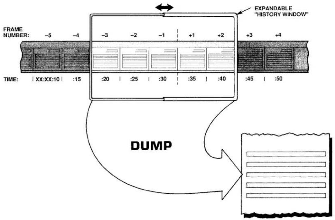
Thus, by commanding
$$ \mathbf {Z U M} \mathbf {n} = \mathbf {s} [ \mathbf {C R} ] $$
you will increase by "s" FRAMES the SEARCH DEPTH for every "NON-STATISTICAL" PLAYBACK PSEUDOCHANNEL of Recorder No. n. The effect is thus to displace all of the recorder's "NON-STATISTICAL" PLAYBACK PSEUDOCHANNELS backwards in time by the same number of FRAMES ("s"). This SEARCH DEPTH "offset" is limited by the total DEPTH (D) of the recorder; "s" cannot have a value such that "f" + "s" > D.
Further "run-time" alteration of the SEARCH DEPTH is possible by this form of the command:
$$ Z U M n = s S T E P z [ C R ] $$
Here, "s" is, as before, the SEARCH DEPTH offset; "z" is the magnitude of a DEPTH increment, expressed as a number of FRAMES. Once you have specified a particular value of "z," you can then use your DataPAC's keyboard to move the SEARCH FRAMES for all "NON-STATISTICAL" PLAYBACK PSEUDOCHANNELS of Recorder No. n either forward or backward in time, synchronously:
- To move all SEARCH FRAMES backward in time by an increment of "z" FRAMES, press the keyboard's Back Space key.
- To move all SEARCH FRAMES forward in time by an increment of "z" FRAMES, press the keyboard's Step key. You will be able to move forward by any number of FRAMES up to "s," but no further.
Moving of the SEARCH FRAME for each PLAYBACK PSEUDOCHANNEL will start from the SEARCH DEPTH defined by the offset "s," when added to the SEARCH DEPTH "f" originally specified for that channel. If no "STEP" term is entered in the ZOOM (ZUM) command, the DEPTH increment "z" will automatically default to "1."
The same ZUM command can be applied to Recorder Nos. n through m at the same time by commanding
$$ \text { ZUM n TO m } = \text { s [CR] } \quad \text { or } \quad \text { ZUM n TO m } = \text { s STEP z [CR] } $$
The effects of the ZOOM (ZUM) command are illustrated in Fig. 3.B.4.10. Here, an initial SEARCH DEPTH of "5" has been specified for one or more PLAYBACK PSEUDOCHANNELS assigned to Recorder No. n by one or more commands of the form
$$ \text { PLA } x = \text { REC } n, \text { CHN } y (- 5) [ \text { CR } ] ^ {*} $$
Upon application of the following command, the SEARCH DEPTH for ALL PLAYBACK PSEUDOCHANNELS assigned to Recorder No. n will increase by 7 FRAMES, and a DEPTH increment of 2 FRAMES will be specified for further (keyboard) modification of the SEARCH DEPTH:
$$ \text { ZUM } n = 7 \text { STEP 2[CR] } $$
Pressing the Back Space key will now increase the SEARCH DEPTH by two FRAMES, thus moving the SEARCH FRAME backwards in time. Pressing the Step key will reduce the SEARCH DEPTH by two FRAMES, moving the SEARCH FRAME forward in time.
Fig. 3.B.4.10. "Zooming" a Playback Pseudochannel
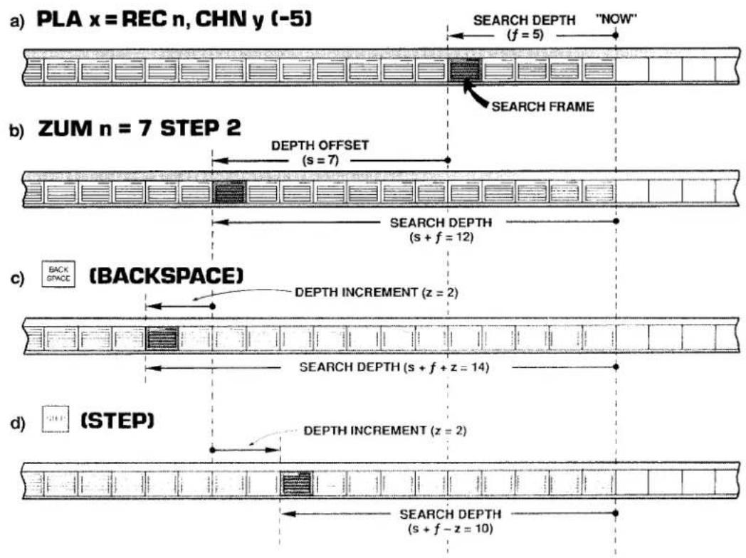
3.B.4 Digital "History" Recording and Playback
To cancel the DEPTH offset now in effect for Recorder No. n or for Recorder Nos. n through m, command, respectively,
$$ \mathbf {Z U M} \mathbf {n} = \mathbf {N} / \mathbf {A} [ \mathbf {C R} ] \text {or} \mathbf {Z U M} \mathbf {n} \mathbf {T O} \mathbf {m} = \mathbf {N} / \mathbf {A} [ \mathbf {C R} ] $$
The SEARCH DEPTH for each playback will now revert to the value "f" specified by that playback's original PLAYBACK (PLA) command.
b. "ZOOMING" A DATA SET
Suppose that Recorder No. 3's LIST includes Data Channel Nos. 1 through 15, and that you wish to observe how the values reported by these channels have changed together in time. In other words, you wish to be able to display on the same CRT page the readings that all of these channels reported at a given time in the past.
1. SET UP PLAYBACK "SET"
Your first step would be to set up fifteen VIDEO PLAYBACK PSEUDOCHANNELS, assuming that you have already composed a PAGE FORMAT for their display (see Section d.8, above). Let us call these PLAYBACK PSEUDOCHANNELS Nos. 1001 through 1015. In order to achieve "time coherence" for the entire set of DATA-CHANNEL readings, you will have to specify the same SEARCH DEPTH for all fifteen playbacks. Since you want maximum "zoomability" for your playbacks, you should set an initial SEARCH DEPTH of only "1." Your playback setup commands would therefore take this form:
$$ \begin{array}{c} \text {PLA 1001 = REC 3, CHN 1 (-1) [CR] ^ {}} \ \text {PLA 1002 = REC 3, CHN 2 (-1) [CR] ^ {}} \ \vdots \ \vdots \ \vdots \end{array} $$
$$ \text { PLA } 1 0 1 5 = \text { REC } 3, \text { CHN } 1 5 (- 1) [ \mathrm{CR} ] ^ {*} $$
With no further alteration of the SEARCH DEPTH, the display of these PLAYBACK PSEUDOCHANNELS will show the values reported by the corresponding DATA CHANNELS at the last recording to have been made—that is, one FRAME "ago."
2. SEARCH FRAME INDICATION
You will want to include on the same CRT display a means of identifying the current SEARCH FRAME—that is, the FRAME in memory from which the displayed data set is currently being taken. You can identify the SEARCH FRAME by its SERIAL NUMBER, in which case you will set up an additional PLAYBACK PSEUDOCHANNEL for display on the same video page:
$$ \text { PLA } 1 0 1 6 = \text { REC } 3, \text { SER } (- 1) [ \text { CR } ] ^ {*} $$
Or you can use FRAME TIME (integral or fractional) for purposes of identifying the current SEARCH FRAME:
$$ \begin{array}{l} \text { PLA 1016 } = \text { REC 3, TME (-1) [CR]} ^ {} \ \text { PLA 1016 } = \text { REC 3, TMF (-1) [CR]} ^ {} \end{array} $$
Or you may set up playbacks for simultaneous display of both SERIAL NUMBER and TIME.
The important thing is, of course, that ALL PLAYBACK PSEUDOCHANNELS, including SEARCH FRAME indicator(s), be set at the same initial FRAME DEPTH ("1").
3. "ZOOM" TO EARLIER SEARCH FRAME
Suppose you now want to look at the state of this data set that existed ten FRAMES ago, and then to be able to move the SEARCH FRAME either backwards or forwards three FRAMES at a time, by means of the Back Space or Step key, respectively. You would enter a command of
$$ \text { ZUM 3 } = 9 \text { STEP 3 [CR] } $$
which would cause the displayed data for all fifteen channels (plus the SEARCH FRAME indicator) to move "coherently" backwards in time.
C. "FREEZING" THE SEARCH FRAME: FRZ COMMAND
In Section d.8 it was explained that a playback's SEARCH FRAME will normally advance, FRAME by FRAME, as each new recording is made. This is illustrated in Fig. 3.B.4.5. The FREEZE (FRZ) command, however, lets you specify a SEARCH FRAME that will not be affected by continued recordings.
The FRZ command is very similar to the ZOOM (ZUM) command. With it, you will specify a DEPTH offset "s" and (optionally) a DEPTH increment "z":
$$ F R Z n = s S T E P z [ C R ] $$
Thus, a command of
$$ \text { FRZ 3 } = 2 5 \text { STEP 5 [CR] } $$
will increase the present SEARCH DEPTH for every playback assigned to Recorder No. 3 by 25 FRAMES, and will provide for further keyboard modification of the SEARCH DEPTH by individual increments of 5 FRAMES, backward or forward. This time, however, the SEARCH FRAME will continue to be the FRAME specified by the above command, even as subsequent recordings are made by Recorder No. 3 (in this case, it is the SEARCH DEPTH itself that increases by one FRAME with each new recording). As stated in Section d.8(d), above, the application of a FRZ command to a given recorder WILL DISABLE ANY AND ALL "STATISTICAL" PLAYBACKS SET UP FOR THAT RECORDER AS LONG AS THE COMMAND IS IN EFFECT.
The same FRZ command can be applied to Recorder Nos. n through m at the same time by commanding
$$ \text { FRZ n TO m } = \text { s [CR] } \quad \text { or } \quad \text { FRZ n TO m } = \text { s STEP z [CR] } $$
To cancel the DEPTH offset provided by the last FREEZE (FRZ) command applied to Recorder No. n or to Recorder Nos. n through m, command, respectively,
$$ \text { FRZ } \mathbf {n} = \mathbf {N} / \mathbf {A} [ \mathbf {C R} ] \quad \text { or } \quad \text { FRZ } \mathbf {n} \text { TO } \mathbf {m} = \mathbf {N} / \mathbf {A} [ \mathbf {C R} ] $$
Note that when the SEARCH DEPTH (which, again, increases with every new recording) becomes equal to the recorder's overall DEPTH, this "N/A" condition will automatically go into effect. Note also that the ZOOM (ZUM) and FREEZE (FRZ) commands are mutually exclusive; application of one command to a given recorder will supersede any prior application of the other command to the same recorder.
9. HISTORY REPLAY: RPL COMMAND
a. INITIATING AND TERMINATING REPLAYS
The REPLAY (RPL) command is normally applied after recording has stopped. It lets you review—at a selected "replay rate"—ALL stored FRAMES for any and all "NON-STATISTICAL" PLAYBACK PSEUDOCHANNELS assigned to a given recorder. The effect of the RPL command is to make the recorder's initial SEARCH FRAME the "oldest" FRAME in memory, and then to successively decrease the current SEARCH DEPTH one FRAME at a time, until the "newest" FRAME (the last to have been recorded) is reached. You will specify the time interval at which the replay is to step "forward" in time toward the latest recorded FRAME as the SEARCH DEPTH is continuously decreased.
Thus, the "replay" function permits "slow motion" playback of all data recorded during a fast event, or a fast review of all data recorded for a test or process of long duration.
If desired, the entire replay process may be indefinitely repeated. That is, after the SEARCH DEPTH has been reduced to only "1"-and the current SEARCH FRAME is therefore the last FRAME to have been recorded-passage of the specified time interval will cause the SEARCH FRAME to return to the "oldest" FRAME in memory.
To initiate a single "history replay" for all "NON-STATISTICAL" PLAYBACK PSEUDO-CHANNELS set up for Recorder No. n, command
$$ \text { RPL } n = \text { INT } t [ \text { CR } ] $$
where "t" is a number from 0 through 15 indicating the desired "clock-time" interval at which the replay is to step "forward":
| 0 = 10 millisec | 6 = 1 sec | 11 = 1 min |
| 1 = 20 millisec | 7 = 2 sec | 12 = 2 min |
| 2 = 50 millisec | 8 = 5 sec | 13 = 5 min |
| 3 = 0.1 sec | 9 = 10 sec | 14 = 10 min |
| 4 = 0.2 sec | 10 = 20 sec | 15 = 20 min |
| 5 = 0.5 sec |
As stated in Section d.8(d), above, the application of a RPL command to a given recorder WILL DISABLE ANY AND ALL "STATISTICAL" PLAYBACKS SET UP FOR THAT RECORDER AS LONG AS THE COMMAND IS IN EFFECT.
To initiate repeated "history replays" for all "NON-STATISTICAL" PLAYBACK PSEUDO-CHANNELS set up for Recorder No. n, command
$$ \mathbf {R P L} \mathbf {n} = \text { INT } \mathbf {t}, \mathbf {R} [ \mathbf {C R} ] $$
To terminate the replay currently in progress—either single or repeated—command
$$ \mathbf {R P L} \mathbf {n} = \mathbf {N} / \mathbf {A} [ \mathbf {C R} ] $$
Note that each of the above REPLAY (RPL) commands can be applied to Recorder Nos. n through m at the same time, by entering the corresponding "range" form of the command:
$$ \begin{array}{r l} & \text { RPL n TO m = INT t [CR] } \ & \text { RPL n TO m = INT t, R [CR] } \ & \text { RPL n TO m = N / A [CR] } \end{array} $$
b. MONITORING REPLAYS: ZUM COMMAND
Continuous monitoring of the current replay SEARCH DEPTH is possible by means of the "READ" form of the ZOOM (ZUM) command, described in Section e.8. Thus, by typing an interrogation of
ZUM [CR]
on the keyboard, while a replay is in progress, you can invoke a BILLBOARD display of the number of FRAMES yet to be replayed (until the "newest" FRAME is reached). Until the ZUM command is cancelled or another keyboard command subsequently entered, this replay SEARCH DEPTH, which decreases by "1" with every replayed FRAME, will remain on display.
Auxiliary Computer Interface: Model 10BACIA Auxiliary Computer Interface Card

DAYTRONIC
System 10 Guidebook
PLEASE NOTE THE FOLLOWING NEW "BACI" PRODUCTS:
1. Model 10BACIA Auxiliary Computer Interface Card
The Model 10BACIA replaces the Model 10BACI discussed in this section. Note, however, that everything said in this section concerning the 10BACI applies equally to the 10BACIA. The primary functional difference between these two versions is that, by virtue of the FRAME CHANNELS (FCH) command, the 10BACIA allows the transmission of a prespecified "frame" of time-coherent channel data. This is treated in 3.B.5 Supplement No. 1 (Model 10BACIA New Features). Also, the 10BACIA can be readily converted to a Model 10BACI-422 by addition of the optional Model 10422BP RS-422 Backplane (see below).
2. Model 10BACI-422 RS-422 Auxiliary Computer Interface Card
The Model 10BACI-422 is equivalent to a Model 10BACIA with an integral RS-422 hardware interface on a 9-pin D subminiature female socket (in place of the 10BACIA's standard RS-232-C interface). The RS-422 interface includes an extra pair of wires for communication of an external synchronizing pulse. Thus, the addition of RS-422 interface hardware to the 10BACIA allows timed synchronous data collection, controlled by a master timing pulse, when the 10BACI-422 is used in a "System 10/2000" DataPAC. Use of the 10BACI-422—particularly in conjunction with the Model 10K488 Data Concentrator—is treated in 3.B.5 Supplement No. 2 (Model 10BACI-422).
3. Model 10BACI-488 IEEE-488 Auxiliary Computer Interface Card
The Model 10BACI-488 is equivalent to a Model 10BACIA with a 24-pin parallel port for standard TALKER/LISTENER communications with an IEEE-488 bus (in place of the 10BACIA's standard RS-232-C interface). Setup and use of the 10BACI-488 is treated in 3.B.5 Supplement No. 3 (Model 10BACI-488).
4. FP (Floating Point) Option
THIS OPTION APPLIES ONLY TO THE MODEL 10BACI-488 IEEE-488 AUXILIARY COMPUTER INTERFACE CARD, AND IS AVAILABLE ONLY ON SPECIAL REQUEST. It allows the 10BACI-488 to issue data for all scanned channels or for a specified range of channels in either IEEE or DEC FLOATING-POINT FORMAT. Setup and use of the FP Option is treated in 3.B.5 Supplement No. 4 (10BACI "Floating Point" Option).
5. Model 10422BP RS-422 Backplane
By replacing the standard RS-232 backplane of a Model 10BACIA with the mainframe-mounted Model 10422BP, you can convert the 10BACIA to a Model 10BACI-422 (see above). Note that the 10422BP may also be used with an older Model 10BACI, but in this case the synchronization features of the 10BACIA and 10BACI-422 will not be available.
Every Model 10BACI Auxiliary Computer Interface Card provides the DataPAC in which it is installed with an "auxiliary" full-duplex RS-232-C interface (hereafter referred to as an "ACI"). As seen by a connected external RS-232-C device-computer, terminal, printer, recorder, etc.-every ACI behaves identically to the DataPAC's standard COMPUTER INTERFACE PORT ("CIP"). That is, a standard MNEMONIC COMMAND issued to an ACI by an RS-232-C device connected to that ACI will invoke from the ACI a response identical in form to the response the CIP would produce to the same command. For example, a DUMP (DMP) command issued to an ACI will cause it to "dump" data; a SEND (SND) command issued to an ACI will cause it to "send" the specified message; a COLUMNS (CLM) command will establish columnar format for subsequent STREAM (STR) and HARDCOPY (HCY) outputs from the ACI; and so on. In addition, the ACI will produce appropriate responses to all standard "READ" COMMANDS recognized by the CIP.
The number of ACI's a DataPAC can have is limited only by the number of available B SLOTS.
As stated above, the activity of a given ACI can be directly controlled by the external RS-232-C device to which it is connected. IT CAN ALSO BE CONTROLLED BY MNEMONIC COMMANDS ENTERED THROUGH THE DATAPAC'S EXTENDED KEYBOARD OR COMPUTER INTERFACE PORT (CIP). AS EXPLAINED IN THE FOLLOWING SECTIONS, KEYBOARD OR CIP CONTROL OF AN ACI CAN BE EFFECTED BY ONE OF THREE "RUN-TIME" COMMANDS: ATTACH (ATT), VIA (VIA), OR COMMUNICATIONS (COM).
The ATTACH (ATT) command lets you establish a direct and exclusive "command route" between a given command source (KEYBOARD or CIP) and the Model 10BACI occupying a given DataPAC B SLOT. It is used primarily for setup of the ACI in question or for subsequent interrogation of the ACI for its own setup parameters. It is cancelled by the DETACH (DET) command.
The VIA (VIA) command serves as a "one-line" ATTACH (ATT) command. By prefixing VIA to any standard MNEMONIC COMMAND, you can route that command directly and exclusively to the Model 10BACI occupying a given DataPAC B SLOT, without having first to "attach" that SLOT to the keyboard or CIP.
The COMMUNICATIONS (COM) command lets you designate a "DEFAULT COMMUNICATIONS PORT" (DCP) for the DataPAC. The DCP is the single system RS-232-C INTERFACE PORT which will respond to all subsequent port-related IMPERATIVE and SETUP COMMANDS received by the DataPAC from the keyboard or executed as a result of an EXECUTE (EXU) or COMMAND (CMD) command. Port-related IMPERATIVE COMMANDS include DUMP (DMP), STREAM (STR), SEND (SND), LOCK (LOK), etc.; port-related SETUP COMMANDS include BAUD RATE (BAU), DELAY (DLY), HEADER (HDR), and OUTPUT TERMINATOR (OPT). A full list of COM-affected commands is given in Section d.1, below). The DCP behaves exactly like the DataPAC's COMPUTER INTERFACE PORT (CIP), as seen from a connected external RS-232-C device. In the absence of any ACI's, the DCP is the CIP. As explained in Section d, below, ATTACH (ATT) and VIA (VIA) will both override the current COM assignment, as will commands received by an ACI from its connected RS-232-C device.
The Model 10BACI is to be regarded as a system "COPROCESSOR." Thus, in addition to an "auxiliary" RS-232-C interface, every ACI also provides an onboard DATA RAM. As explained in Section c.7, below, externally acquired numeric and logic data can thus be downloaded from the connected RS-232-C device to the ACI itself. With each internal scan cycle, this data will be "locally" updated (at the ACI), to be read from there by the DataPAC's CENTRAL PROCESSOR. Such local handling of downloaded data by the ACI helps preserve the DataPAC's high scan speed when a large number of inputs is involved.
The Model 10BACI has ten front-panel STATUS INDICATORS. The top four lights are red, to indicate "error" or "alert" conditions. The remaining lights are green.
The DTR, RTS, ERR, CHR, MNE, RET, XMT, and RCV lights are identical in function to the corresponding indicators on the DataPAC's INTERFACE CARD, except that they now refer to line activity at the respective ACI. See Section 1.A.4 of this Guidebook for an explanation of these indicators. The OFF indicator is not presently used.
The COM indicator will light when the ACI in question has been designated to be the DataPAC's single DEFAULT COMMUNICATIONS PORT (DCP) by a COMMUNICATIONS (COM) command (Section d.1, below). When no ACI's COM light is on, it means that the DCP is the COMPUTER INTERFACE PORT (CIP).
Before entering any SETUP COMMANDS for a given ACI, you should first turn ON the DataPAC's EEPROM Switch (the ACI has no EEPROM Switch of its own, since it reads the CENTRAL PROCESSOR'S EEPROM Switch).
1. THE "ATTACH (ATT)" AND "DETACH (DET)" COMMANDS
"Attach" the given ACI either to the DataPAC's EXTENDED KEYBOARD or to the COMPUTER INTERFACE PORT (CIP), whichever command source you wish to use (setup procedures are usually performed through the keyboard).
Thus, if you want to "attach" the ACI of the Model 10BACI card occupying B SLOT No. s to the DataPAC's keyboard, enter the following command, via the keyboard:
$$ \mathbf {A T T} = \mathbf {s} [ \mathbf {C R} ] $$
All subsequent keyboard-entered MNEMONIC COMMANDS will now be "heard" ONLY by the Model 10BACI in question; they will be ignored by all other cards in the system. Commands entered via the CIP, however, will in this case continue to be received by all cards.
If the above ATT command is entered via the COMPUTER INTERFACE PORT, then the 10BACI in B SLOT No. s will be exclusively "attached" to the CIP. Commands entered via the keyboard, however, will in this case continue to be received by all cards.
The DETACH (DET) command serves to cancel the ATTACH (ATT) command. Thus, to "detach" the 10BACI presently "attached" to either the DataPAC's keyboard or CIP, command, via the keyboard or CIP, respectively,
DET [CR]
Note that ATTACH (ATT) and DETACH (DET) are "RUN-TIME" COMMANDS, and may therefore be applied at any time during normal operation.
Note too that the VIA (VIA) command (Section d.2, below) permits momentary "attachment" of a 10BACI for the purpose of directing a single MNEMONIC COMMAND to that 10BACI without prior application of an ATTACH (ATT) command.
You may now issue SETUP COMMANDS directly to the 10BACI in question via the command source you have "attached" to it (keyboard or CIP).
2. ACICABLING
For general RS-232-C Interface Cabling, see Section 2.B.2 of this Guidebook. The remarks made there concerning COMPUTER INTERFACE PORT connections apply equally to every "AUXILIARY" COMPUTER INTERFACE.
3. SETTING ACI PROTOCOL: BAU COMMAND
FOR PROPER DATA INTERCHANGE BETWEEN AN ACI AND A CONNECTED RS-232-C DEVICE TO OCCUR, THE ACI MUST BE SET TO CONFORM EXACTLY WITH THE PROTOCOL STIPULATED BY THE CONNECTED DEVICE.
For an explanation of RS-232-C "protocol" characteristics, see Section 2.B.2 of this Guidebook.
NOTE
IN ORDER TO SET OR RESET THE PROTOCOL VALUES FOR AN ACI, YOU MUST USE THE BAUD RATE (BAU) COMMAND. Unlike the DataPAC's INTERFACE CARD, the 10BACI has no Protocol Switches, and is not affected by the "MENU" Setup Program discussed in Section 2.B.2.
After "attaching" the ACI in question to the DataPAC's keyboard or CIP (as above), enter via the keyboard or CIP, respectively,
$$ \mathbf {B A U} = \mathbf {b}, \mathbf {d}, \mathbf {s}, \mathbf {p} [ \mathrm{CR} ] ^ {*} $$
where
b is the BAUD-RATE selection code:
| 2 = 1200 | 6 = 19.2K |
| 3 = 2400 | 7 = 153.6K |
| 4 = 4800 | 8 = 38.4K |
| 5 = 9600 | 9 = 76.8K |
(Note that a Baud rate of 300 is not available for the 10BACI. However, rates of 38.4K and 76.8K are available, which are not offered by the DataPAC's CIP.)
d is the NUMBER OF DATA BITS (7 or 8)
s is the NUMBER OF STOP BITS (1 or 2)
p is the PARITY selection code:
$$ 0 = \text { NONE }; 1 = \text { ODD }; 2 = \text { EVEN } $$
4. SETTING ACI COMMAND TERMINATOR: CMT COMMAND
Prior to shipment, every ACI is factory-set for a COMMAND TERMINATOR of CARRIAGE RETURN ([CR]). If you intend to issue commands to an ACI from an external RS-232-C device that normally terminates its transmissions with a character other than [CR], you will have to apply a COMMAND TERMINATOR (CMT) command to that ACI, having first "attached" the ACI to the respective command source (keyboard or CIP). Enter a command of
$$ \mathbf {C M T} = \mathbf {c} [ \mathbf {C R} ] ^ {*} $$
where "c" is any single ASCII character, with the exception of [ESC], which will never be recognized by the ACI as a COMMAND TERMINATOR. If the specified terminator is an ASCII CONTROL CHARACTER—such as [CR], [LF], [FF], etc.—it must be entered as a hexadecimal word in brackets. Two-character hexadecimal equivalents for standard ASCII CONTROL CHARACTERS are given in Table 1.H.2, Section 1.H.3 of this Guidebook.
5. ACI OUTPUT FORMATTING
ALL MNEMONIC COMMANDS THAT RELATE TO THE FORMATTING OF TRANSMISSIONS FROM THE DATAPAC'S COMPUTER INTERFACE PORT MAY BE USED TO FORMAT TRANSMISSIONS FROM AN ACI, AFTER THE ACI HAS BEEN "ATTACHED" TO THE RESPECTIVE COMMAND SOURCE (KEYBOARD OR CIP). IN ALL CASES, THE COMMAND SYNTAX IS THE SAME.
3.B.5 Auxiliary Computer Interface
Formatting commands (described in Section 1.H.3 of this Guidebook) include
| ECHO (ECO)....to include Channel-Number "echo" in CHN, DMP, or SNP outputs | |
| NO CHANNEL (NCH)....to cancel ECO | |
| LIMITS (LIM)....to include LIMIT-ZONE indication in CHN, DMP, or or SNP outputs | |
| NO LIMITS (NOL)....to cancel LIM | |
| HEADER (HDR)....to specify HEADER string for STR and HCY outputs | |
| TAILER (TLR)....to specify TAILER string for STR and HCY outputs | |
| CHARACTERS PER CHANNEL (CPC)....to specify number of DATA-FIELD spaces for STR and HCY outputs | |
| COLUMNS (CLM)....to set columnar format for STR and HCY outputs | |
| OUTPUT TERMINATOR (OPT)....to set OUTPUT ("END-OF-LINE") TERMINATOR | |
| END OF TRANSMISSION (EOT)....to set END-OF-TRANSMISSION TERMINATOR different from OUTPUT ("END-OF-LINE") TERMINATOR | |
| DELAY (DLY)....to set intertransmission delay time for DMP, STR, HCY, SNP, and LZN outputs |
6. SETTING OTHER ACI COMMUNICATIONS FEATURES
CERTAIN MNEMONIC COMMANDS THAT RELATE TO SPECIAL COMMUNICATIONS FEATURES OF THE DATAPAC'S COMPUTER INTERFACE PORT MAY ALSO BE APPLIED TO AN ACI, AFTER THE ACI HAS BEEN "ATTACHED" TO THE RESPECTIVE COMMAND SOURCE (KEYBOARD OR CIP). IN ALL CASES, THE COMMAND SYNTAX IS THE SAME.
Such commands (described in Section 2.B.6 of this Guidebook) include
SEND (SND) ......to cause the ACI to transmit a specified ASCII string
7. ACI "LOCAL" CHANNELS AND BITS
a. LOCATING "OFF-BOARD" VOLATILE DOWNLOAD PSEUDOCHANNELS TO THE 10BACI: LCT AND RST COMMANDS
To arrange for an ACI to be responsible for updating the RAM-stored data value of a given VOLATILE DOWNLOAD PSEUDOCHANNEL No. x, you can use the LOCATE (LCT) command:
$$ \mathbf {L C T} \mathbf {x} = \mathbf {s} [ \mathbf {C R} ] ^ {*} $$
where "s" is the number of the B SLOT occupied by the Model 10BACI in question. Note that system "REAL" CHANNELS, CONVERSION CHANNELS, and NONVOLATILE ("KEEP-ALIVE") PSEUDOCHANNELS may not be "located" to an ACI.
APPLICATION OF THE ABOVE COMMAND WILL AUTOMATICALLY ASSIGN A "TYPE" DESIGNATION OF DA TO CHANNEL NO. x.
Although Channel No. x is now "off-board" from the CENTRAL PROCESSOR's point of view, it may be subsequently interrogated or transmitted just like any other system DATA CHANNEL through an appropriate command communicated to the DataPAC through the keyboard or CIP (CHANNEL (CHN), DUMP (DMP), STREAM (STR), etc.)—or by such a command communicated directly to the ACI by the external RS-232-C device to which it is connected. Channel No. x's current data value may also be incremented or decremented, just like that of any other DOWNLOAD PSEUDOCHANNEL, by means of an INCREMENT (INC) or DECREMENT (DEC) command applied to the DataPAC or directly to the ACI (see Section 2.M.1 of this Guidebook). As mentioned above, such "local" control of downloaded numeric data helps preserve the DataPAC's high internal scan rate.
The above LOCATE (LCT) command can only be cancelled by applying a RESET (RST) command of
RST x [CR] \*
This command will return the responsibility of updating Channel No. x to the DataPAC's CENTRAL PROCESSOR, and will "retype" the channel as D0 (for channel "reconfiguration," see Appendix C of this Guidebook). The "WRITE" form of the TYPE (TYP) command will have no effect on Channel x.
b. SOURCING LOGIC BITS TO THE 10BACI: SRC COMMAND
As a system "COPROCESSOR," a Model 10BACI can serve as the immediate "LOGIC SOURCE" of one or more system LOGIC BITS, from the CENTRAL PROCESSOR's point of view (for "Logic Sourcing," see Section 2.H.2 of this Guidebook). A LOGIC BIT sourced to an ACI can only be set or reset by means of an external bit-setting command directed to the ACI (SET BIT (BIT), HEXADECIMAL (HEX), BINARY (BIN), or BINARY CODED DECIMAL (BCD)).
Thus, to "source" a given Bit No. r to the 10BACI occupying B SLOT No. s, enter the following LOGIC SOURCE (SRC) command:
$$ \mathbf {S R C} \mathbf {r} = \mathbf {B s} [ \mathbf {C R} ] ^ {*} $$
Note that the Slot-Number entry must be preceded by the letter "B."
To return "EXTERNAL" control of Bit No. r to the CENTRAL PROCESSOR, command
$$ \text { SRC } r = \text { EXT } [ \text { CR } ] ^ {*} $$
IMPORTANT
MAKE SURE THE DATAPAC'S EEPROM SWITCH IS ON WHEN YOU ENTER THIS COMMAND.
See Sections 2.H.2 and 4.B for a full treatment of the LOGIC SOURCE (SRC) command.
1. DESIGNATING THE DEFAULT COMMUNICATIONS PORT: COM COMMAND
The COMMUNICATIONS (COM) command lets you designate the DEFAULT COMMUNICATIONS PORT (DCP) for the DataPAC. The DCP is the single RS-232-C INTERFACE PORT which alone will, by default, receive and respond to every subsequent port-related IMPERATIVE or SETUP COMMAND applied to the DataPAC via the keyboard or via an EXECUTE (EXU) or COMMAND (CMD) function. Any command received by a specific port (ACI or CIP) from an RS-232-C device directly connected to that port or from a command source directly "attached" to that port by means of an ATTACH (ATT) or VIA (VIA) command will be answered only at that port, whether or not it is the DataPAC's current DCP.
COM-affected commands presently include the following:
BAU, CLM, CMT, CPC, DLY, DMP, ECO, EOT, ESC, HCY, HDR, LIM, LOK, NCH, NOL, OPT, SND, SNP, STR, TLR, UNL
Note that neither the CHANNEL (CHN) command nor the LIMIT ZONE (LZN) command is listed among the above "COM-affected" commands. This is because, although CHN (in its CHN [CR] form) and LZN are included among the standard "Data Transmission" commands described in Section 1.H.2 of this Guidebook, they are both actually "READ" commands, the "location of response" to which will always depend on the "location of entry" (see Section 1.A.3(d) for "Read Commands and Responses").
To designate as the DCP the ACI provided by the Model 10BACI card installed in B SLOT No. s, command
$$ \mathbf {C O M} = \mathbf {s} [ \mathbf {C R} ] ^ {*} $$
Note that this is a SETUP COMMAND and requires that the DataPAC's EEPROM Switch be ON. Its effect will be to write into the CENTRAL PROCESSOR'S EEPROM the "port address" to which any of the above commands is now to be exclusively routed, unless this command is otherwise directed to a specific port by an ATTACH (ATT) or VIA (VIA) command, or by a connected RS-232-C device.
YOU MAY, HOWEVER, "TEMPORARILY" REASSIGN TO ANOTHER ACI THE FUNCTION OF DCP, DURING NORMAL OPERATION, WITHOUT HAVING TO TURN ON THE EEPROM SWITCH, BY COMMANDING
$$ \mathbf {C O M} = \mathbf {s _ {1}} [ \mathbf {C R} ] $$
where "s1" is a B-SLOT Number different from the original "s." Upon recycling of system power, the COM assignment will return to the port specified while the EEPROM was enabled.
To return to the DataPAC's COMPUTER INTERFACE PORT the function of DCP, command
$$ \mathbf {C O M} = 2 6 [ \mathbf {C R} ] ^ {*} $$
Concerning the COM command, you should note the following:
a. Although the COMMUNICATIONS (COM) command has a "RUN-TIME" form, you are advised not to change the DEFAULT COMMUNICATIONS PORT assignment while the system is in operation, unless you are sure that
- no output is currently in progress as a result of the present COM assignment, and
- the rerouting of automatic or semi-automatic data gathering functions (e.g., external computer interrogation or EXECUTE-driven commands) will not result in error.
Remember that COM is essentially a system setup command; a change in DCP assignment will generally entail a change in the overall functioning of the system.
b. By changing the current DEFAULT COMMUNICATIONS PORT from one system port to another, YOU DO NOT THEREBY TRANSFER THE EXISTING SETUP CHARACTERISTICS OF THE ONE PORT TO THE OTHER. Every system port must be individually set up by appropriate commands (BAU, CMT, OPT, EOT, HDR, DLY, etc.) issued directly to that port by a connected RS-232-C device or—when that port is the system DEFAULT COMMUNICATIONS PORT—by keyboard.
C. Be careful not to confuse the ATTACH (ATT) and COMMUNICATIONS (COM) commands.
ATTACH (ATT) is a general command used to "attach" a DataPAC command source (KEYBOARD or COMPUTER) to the card occupying a specific B SLOT, usually for purposes of setting up the card or of interrogating it for its own specific setup parameters. Remember, however, that ANY standard MNEMONIC COMMAND may be routed to a specific B CARD after that card has been "attached" to the keyboard or CIP. By this means—as well as by the VIA (VIA) command, below—port-specific imperatives such as DMP, STR, SND, LOK, etc., can be issued to an ACI that is not the currently specified DEFAULT COMMUNICATIONS PORT.
COMMUNICATIONS (COM), on the other hand, is used to specify a particular RS-232-C INTERFACE PORT to be the only port that will "hear" and respond to subsequent keyboard-entered or automatically executed commands that relate to the activity of such a port (usually these will be transmission-initiating imperatives like DMP, STR, HCY, SND, etc.). THE COM COMMAND WILL NOT-AND SHOULD NOT-NORMALLY BE USED TO SET UP AN ACI OR TO INTERROGATE AN ACI FOR ITS SETUP PARAMETERS.
d. If the DataPAC's COMPUTER INTERFACE PORT is not the present DEFAULT COMMUNICATIONS PORT (i.e., if COM = 26 [CR] is not in effect), a PAGE (PAG) command contained in an EXECUTE (EXU) string will not work (for PAG, see Section 2.C.3; for EXU, see Section 2.K.2). You will have to prefix the PAG command with
VIA 26
to properly route it to the Video Card Set (see below).
2. ROUTING SINGLE COMMANDS TO AN ACI: VIA COMMAND
The VIA (VIA) command serves as a "one-line" ATTACH (ATT) command, allowing you to route a single MNEMONIC COMMAND directly and exclusively to a given Model 10BACI, without having first to "attach" that SLOT to the keyboard or CIP by an ATTACH (ATT) command or to designate the ACI in question to be the DEFAULT COMMUNICATIONS PORT by a COMMUNICATIONS (COM) command.
Thus, to issue to the 10BACI occupying B SLOT No. s the MNEMONIC COMMAND represented by the ASCII STRING "\$," at any time during normal operation, command
VIA s, \$ [CR]
where "\$" can consist of up to 80 ASCII characters, literally stating the command to be routed to the 10BACI occupying B SLOT No. s.
Section 3.B.5 Supplement No. 1: Model 10BACIA New Features
The Model 10BACIA Auxiliary Computer Interface Card is identical to the Model 10BACI discussed in Section 3.B.5, except that
- it needs to be told by means of the BCP (BCP) command whether it is working with a 10BCP100(A) or 10BCP200 ("System 10/2000") Central Processor
- it responds to the FRAME CHANNELS (FCH) and MASTER TIMING CLOCK (MTC) commands as explained below
- its response to the DUMP SYSTEM DATA (DSD) command differs from that of the 10BACI
- it can be converted to a Model 10BACI-422 by addition of the Model 10422BP RS-422 Backplane.
1. Ensuring 10BACIA / Central Processor Compatibility: BCP Command
To ensure proper operation of the FRAME CHANNELS (FCH) command, it is necessary for every 10BACIA to know which type of CENTRAL PROCESSOR card is in the DataPAC—a Model 10BCP100/10BCP100A or a Model 10BCP200 (which is used in all "System 10/2000" DataPACs). To inform all 10BACIA's in the DataPAC that they are being used with a 10BCP100 or 10BCP100A, you should make sure that a command of
$$ \mathbf {B C P} = 1 0 0 [ \mathrm{CR} ] ^ {*} $$
is in effect; to inform all 10BACIA's that the DataPAC has a 10BCP200, make sure that
$$ \mathbf {B C P} = 2 0 0 [ \mathbf {C R} ] ^ {*} $$
is in effect.
2. Transmitting a Time-Coherent Data "Frame": FCH Command
The 10BACIA can be instructed to load Channels x through y into an output buffer at the end of every complete scan cycle. To do so, you should direct to the 10BACIA a FRAME CHANNELS command of
$$ \mathbf {F C H} = \mathbf {x}, \mathbf {y} [ \mathbf {C R} ] ^ {*} $$
This command allows a time-coherent "frame" of data (i.e., the data for Channels x through y) to be transferred to the 10BACIA's output buffer as soon as this data set has been fully scanned and posted. During loading of the buffer, the 10BACIA will delay responding to a request for output until the loading has been completed (about 5 milliseconds). If the 10BACIA is in the process of transmitting data at the end of the scan cycle, loading is suspended. The currently loaded "buffer frame" of data can be subsequently transmitted from the 10BACIA via any of the standard channel-outputting commands (DMP, STR, HCY, SNP, DSD, DSF, etc.).
NOTE: The FCH command requires that the EEPROM Write Protect Switch be ON. It does not require the presence of the Model 10BCP200 CENTRAL PROCESSOR. It may be applied to any system 10BACIA card, or to any Model 10BACI-422 or 10BACI-488. It can be sent directly to the 10BACIA via the 10BACIA's RS-232-C port, the DataPAC's keyboard or standard Computer Interface, or an EXECUTE (EXU) or COMMAND (CMD) function (see Section 3.B.5.d).
3. The MTC Command
When a Model 10BACIA has been converted to a Model 10BACI-422 and is used in a "System 10/2000" DataPAC (i.e., a DataPAC with the Model 10BCP200 CENTRAL PROCESSOR), a MAS-TER TIMING CLOCK (MTC) command of MTC = ON [CR] can be applied in conjunction with a CLOCK command of CLK = ON [CR] to synchronize the DataPAC's time-of-day clock with an external timing pulse communicated to the 10BCP200 by the 10BACI-422. See Section 3.B.5 Supplement No. 2 (Model 10BACI-422) for details concerning the MTC command.
NOTE HERE THAT FOR A MODEL 10BACI ITSELF—WITHOUT RS-422 INTERFACE HARDWARE—THE MTC = OFF [CR] COMMAND SHOULD ALWAYS BE IN EFFECT; THE MTC = ON [CR] COMMAND SHOULD NEVER BE APPLIED TO A MODEL 10BACIA.
4. Response to DSD Command
The format of the output produced by the Model 10BACIA in response to a DUMP SYSTEM DATA (DSD) command is different from that produced by the 10BACI. This output is shown in Fig. 1, below. See the latest version of Appendix L.1 ("Binary Transmission Mnemonics") for complete details.
Fig. 1 Transmission Format for DSD Command (10BACIA, 10BACI-422, and 10BACI-488)
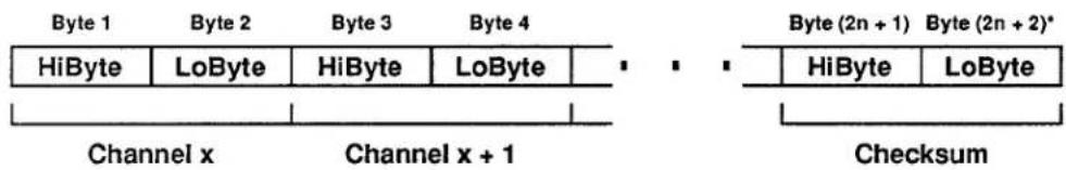
* Where n = the number of channels in the transmitted range (x TO y).
Section 3.B.5 Supplement No. 2: Model 10BACI-422
1. Introduction
The Model 10BACI-422 Auxiliary Computer Interface Card allows direct transmission of data acquired by a "B-Sized" DataPAC to an external device with RS-422 I/O capability, without the need for an external RS-232 to RS-422 adaptor (such as the Model 10E422). It is equivalent to a Model 10BACIA with an integral RS-422 hardware interface on a 9-pin D subminiature female socket (in place of the 10BACIA's standard RS-232-C interface). The RS-422 interface contains an extra pair of wires for communication of an externally sourced synchronizing pulse. This allows timed synchronous data collection, controlled by the external pulse, when the 10BACI-422 is used in a "System 10/2000" DataPAC (i.e., with a Model 10BCP200 CENTRAL PROCESSOR CARD)—as explained in Section 4, below.
While the 10BACI-422 may communicate with any external RS-422 device, it was designed primarily to allow direct data transfer between a "B-Sized" DataPAC and an individual Model 10A422 Communication Buffer Card within a Model 10K488 Data Concentrator, while also allowing the timing pulse generated by the 10K488 to synchronize the collection of data for all connected DataPACs. For use of the 10BACI-422 within a complete 10K488-based data collection system, you should consult the Model 10K488 Instruction Manual.
2. Ensuring 10BACI-422 / Central Processor Compatibility: BCP Command
To ensure proper operation of the FRAME CHANNELS (FCH) command, it is necessary for every 10BAC-422 to know which type of CENTRAL PROCESSOR card is in the DataPAC—a Model 10BCP100/10BCP100A or a Model 10BCP200 (which is used in all "System 10/2000" DataPACs). To inform all 10BACI-422's in the DataPAC that they are being used with a 10BCP100 or 10BCP100A, you should make sure that a command of
$$ \mathbf {B C P} = 1 0 0 [ \mathrm{CR} ] ^ {*} $$
is in effect; to inform all 10BACI-422's that the DataPAC has a 10BCP200, make sure that
$$ \mathbf {B C P} = 2 0 0 [ \mathbf {C R} ] ^ {*} $$
is in effect.
3. Setup of the RS-422 Auxiliary Computer Interface
Pin assignments for the 10BACI-422's 9-pin RS-422 Connector are as follows:
| Pin | Function |
| 1 | COMMAND |
| 6 | COMMAND |
| 4 | RESPONSE |
| 3 | RESPONSE |
| 5 | CLEAR TO SEND |
| 9 | CLEAR TO SEND |
| 7 | SYNC |
| 8 | SYNC |
| 2 | COMMON |
Note that Pins 7 and 8 are dedicated to the externally sourced synchronizing pulse ("SYNC"). If the device to which the 10BACI-422 is connected does not supply such a signal, these pins should be left unconnected (for cabling between a 10BACI-422 and a Model 10A422 Communication Buffer Card, see the Model 10K488 Instruction Manual.)
In the cable connecting the 10BACI-422 and the external RS-422 device, the SHIELD for each "twisted pair" should be connected to "COMMON" (Pin 2). Use BELDEN 9728 DATALENE 100 Ω or equivalent cable.
FOR PROPER DATA INTERCHANGES TO OCCUR BETWEEN THE 10BACI-422 AND AN EXTERNAL RS-422 DEVICE, THE 10BACI-422 MUST BE SET TO CONFORM EXACTLY WITH THE INTERFACE PROTOCOL STIPULATED BY THE CONNECTED DEVICE. For setup of the 10BACI-422 interface protocol using the ATTACH (ATT) and BAUD RATE (BAU) commands, see Section 3.B.5.c.
4. Transmitting a Time-Coherent Data "Frame": FCH Command
SEE 3.B.5 SUPPLEMENT NO. 1 (NEW 10BACIA FEATURES) FOR A DISCUSSION OF THE FRAME CHANNELS (FCH) COMMAND, WHICH APPLIES EQUALLY TO THE MODEL 10BACI-422.
5. Setting Up the Master Timing Clock: CLK and MTC Commands
When an external synchronizing pulse signal is available through the RS-422 interface—as it is when the 10ABACI-422 is communicating with a Model 10K488 Data Concentrator—then you will need to enter a CLOCK (CLK) command and a MASTER TIMING CLOCK (MTC) command in order to "slave" the DataPAC's scan cycle to this "master" pulse signal. These commands are effective only when the DataPAC contains a Model 10BCP200 CENTRAL PROCESSOR CARD (as do all "System 10/2000" DataPACs). NOTE TOO THAT THE EXTERNAL SYNC PULSES MUST BE AT A RATE OF 1 SECOND ± 0.05%.
The purpose of the CLOCK (CLK) command is to synchronize the scanning of data channels to the DataPAC's time-of-day clock. When a command of
$$ \mathbf {C L K} = \mathbf {O F F} [ \mathbf {C R} ] ^ {*} $$
is in effect, there will be no delay between successive scan cycles; each scan will begin as soon as the last one has finished. When, however, a command of
$$ \mathbf {C L K} = \mathbf {O N} [ \mathbf {C R} ] ^ {*} $$
is in effect, data conversion will be paused at the end of each scan until the time-of-day clock registers its next tenth of a second. Thus, a scan will be initiated exactly ten times a second—assuming that a small enough number of channels is being scanned. The CLK command is a SETUP command and requires that the EEPROM Write Protect Switch be ON.
The purpose of the MASTER TIMING CLOCK (MTC) command is to synchronize the DataPAC's time-of-day clock to the externally sourced timing pulse, to within ±2 milliseconds. The synchronized millisecond clock is then used to trigger successive scans at 0.1-second intervals, as directed by the CLK = ON [CR] command. Thus, when a command of
$$ \mathbf {M T C} = \mathbf {O N} [ \mathbf {C R} ] * $$
is in effect, the 10BCP200 will expect regular timing pulses to be received FROM THE SINGLE 10BACI-422 TO WHICH THIS COMMAND WAS DIRECTED.* This command should be applied to one and only one Model 10BACI-422 in the system, since it in effect tells the 10BCP200 which 10BACI-422 to "listen" to for each successive sync pulse. It can be sent directly to the 10BACI-422 via the RS-422 port or through the DataPAC's keyboard or standard Computer Interface (see Section 3.B.5.d).
Concerning the MTC command, note also that
- This is a SETUP command and requires that the EEPROM Write Protect Switch be ON.
- Setting up the clock synchronization is done at system "bootup." POWER MUST THEREFORE BE CYCLED FOR THE MTC COMMAND TO BE EFFECTIVE.
- In order for the MTC = ON [CR] command to be effective, the CLK = ON [CR] command must be in effect.
- To cancel the "slaving" of the time-of-day clock to the external sync pulse, you can send a command of
$$ \mathbf {M T C} = \text { OFF } [ \mathbf {C R} ] ^ {*} $$
to the 10BACI-422 to which the original MTC = ON [CR] was applied.
- The MTC = ON [CR] command should NEVER be applied to a Model 10BACIA Auxiliary Computer Interface Card unless it is equipped with a Model 10422BP RS-422 Backplane connected to an appropriate master timing source.
6. Response to DSD Command
For the format of the output produced by the Model 10BACI-422 in response to a DUMP SYSTEM DATA (DSD) command, see 3.B.5 Supplement No. 1 (Model 10BACIA New Features).
Section 3.B.5 Supplement No. 3:
Model 10BACI-488
1. Introduction
The Model 10BACI-488 allows direct connection of a "B-sized" DataPAC to an IEEE-488 bus, thus eliminating the need for an external RS-232 to IEEE-488 adaptor such as the Model 10CIF488A. It is equivalent to a Model 10BACIA with a 24-pin parallel port for standard IEEE-488 TALKER/LISTENER communications (in place of the 10BACIA's standard RS-232-C interface).
NOTE: While the 10BACI-488 conforms to the hardware protocol of IEEE-488, it does not adhere to the software protocol contained in IEEE-488.2. In addition, the data transfer rate is limited by the rate at which data can be received from the System 10 database (typically 2000 to 3000 channels per second). As a result, the 10BACI-488 transfer rate will be about 15,000 to 17,000 bytes per second.
Note too that the rear connector supplied with the 10BACI-488 covers two "B" SLOTS. The slot at which the card is "located" is the right-hand slot; the left-hand slot is empty.
Everything that is said in Section 3.B.5 (Version SB.3 or higher) about the Model 10BACI Auxiliary Computer Interface Card applies equally to the Model 10BACI-488, EXCEPT THAT
a. Unlike the 10BACI, the 10BACI-488 DOES NOT SUPPORT SERIAL COMMUNICATIONS; therefore, all references to "RS-232-C" interface connections and protocols should be ignored. The 10BACI-488 provides a 24-PIN PARALLEL PORT CONNECTOR (only), as described below.
b. The 10BACI-488 card has on-board DIP switches for assigning a specific bus address to the System 10.
c. The ADDRESS (ADD) and END OR IDENTIFY (EOI) commands have been developed for use with the 10BACI-488. These are given in Section 4, below. In addition, the response of the 10BACI-488 to the FRAME CHANNELS (FCH) and DUMP SYSTEM DATA (DSD) commands is identical to that of the Model 10BACIA (see 3.B.5 Supplement No. 1).
d. The 10BACI's RTS and DTS front-panel STATUS INDICATORS have been replaced by LAD ("Listener Active Device") and TAD ("Talker Active Device"), to indicate the System 10's current bus role.
2. Ensuring 10BACI-488 / Central Processor Compatibility: BCP Command
To ensure proper operation of the FRAME CHANNELS (FCH) command, it is necessary for every 10BAC-488 to know which type of CENTRAL PROCESSOR card is in the DataPAC—a Model 10BCP100/10BCP100A or a Model 10BCP200 (which is used in all "System 10/2000" DataPACs). To inform all 10BACI-488's in the DataPAC that they are being used with a 10BCP100 or 10BCP100A, you should make sure that a command of
$$ \mathbf {B C P} = 1 0 0 [ \mathbf {C R} ] ^ {*} $$
is in effect; to inform all 10BACI-488's that the DataPAC has a 10BCP200, make sure that
$$ \mathbf {B C P} = 2 0 0 [ \mathbf {C R} ] ^ {*} $$
is in effect.
3. Connections
The 10BACI-488's 24-pin PARALLEL PORT connects directly to the IEEE-488 bus, via a cable supplied by the user and conforming to recommended IEEE-488 cable practice. Standard IEEE-488 pinout is employed for this port, as follows:
| Pin No. | Signal Line | Pin No. | Signal Line |
| 1 | DI01 (Data Line) | 13 | DI05 (Data Line) |
| 2 | DI02 (Data Line) | 14 | DI06 (Data Line) |
| 3 | DI03 (Data Line) | 15 | DI07 (Data Line) |
| 4 | DI04 (Data Line) | 16 | DI08 (Data Line) |
| 5 | EOI (End or Identify) | 17 | REN (Remote Enable) |
| 6 | DAV (Data Valid) | 18 | Ground |
| 7 | NRFD (Not Ready For Data) | 19 | Ground |
| 8 | NDAC (Not Data Accepted) | 20 | Ground |
| 9 | IFC (Interface Clear) | 21 | Ground |
| 10 | SRQ (Service Request Line) | 22 | Ground |
| 11 | ATN (Attention) | 23 | Ground |
| 12 | Shield |
4. Setting System 10 IEEE-488 Bus Address
With reference to IEEE-488 bus structure, a System 10 connected via a 10BACI-488 is a "TALKER/LISTENER" device, to which you must assign a specific bus address (any integer from 0 through 30). To do so,
- Turn OFF mainframe power and remove the 10BACI-488 card from its slot (see Appendix B for card insertion and removal).
- Locate the ADDRESS SELECTION SWITCHES on the 10BACI-488 card (see Fig. 1, below). Set these five switches as shown in the table to encode, in binary form, the value of the desired bus address. The address can be any integer from 1 through 30 (address "0" is reserved for the controller, and should not be used). For example, to select an address of "21," set Switches 1 through 5 to form a sequential pattern of "10101" (switch depressed to the left for "1"; to the right for "0"). At any time you may use the ADDRESS (ADD) command, described in the following section, to check the current setting of the ADDRESS SELECTION SWITCHES.
- Return the 10BACI-488 card to its slot, and reactivate the mainframe.
Note that, upon system powerup, the System 10 will be at null (i.e., inactive on the bus) until it is told by the bus controller to be a TALKER or LISTENER.
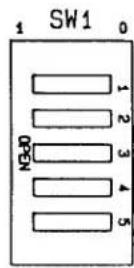
| TALKER/LISTENER ADDRESS SELECTION | ||||||||||||||||||||||||||||||
| 0 | 1 | 2 | 3 | 4 | 5 | 6 | 7 | 8 | 9 | 10 | 11 | 12 | 13 | 14 | 15 | 16 | 17 | 18 | 19 | 20 | 21 | 22 | 23 | 24 | 25 | 26 | 27 | 28 | 29 | 30 |
| 0 | 1 | 0 | 1 | 0 | 1 | 0 | 1 | 0 | 1 | 0 | 1 | 0 | 1 | 0 | 1 | 0 | 1 | 0 | 1 | 0 | 1 | 0 | 1 | 0 | 1 | 0 | 1 | 0 | 1 | 0 |
| 0 | 0 | 1 | 1 | 0 | 0 | 1 | 1 | 0 | 0 | 1 | 1 | 0 | 0 | 1 | 1 | 0 | 0 | 1 | 1 | 0 | 0 | 1 | 1 | 0 | 0 | 1 | 1 | 0 | 0 | 1 |
| 0 | 0 | 0 | 0 | 1 | 1 | 1 | 1 | 0 | 0 | 0 | 0 | 1 | 1 | 1 | 1 | 0 | 0 | 0 | 0 | 1 | 1 | 1 | 1 | 0 | 0 | 0 | 0 | 1 | 1 | 1 |
| 0 | 0 | 0 | 0 | 0 | 0 | 0 | 0 | 1 | 1 | 1 | 1 | 1 | 1 | 1 | 1 | 0 | 0 | 0 | 0 | 0 | 0 | 0 | 0 | 1 | 1 | 1 | 1 | 1 | 1 | |
TALKER/LISTENER
ADDRESS SELECTION
Fig. 1 10BACI-488 Address Selection Switches
5. 10BACI-488 Mnemonic Commands
The following two special commands have been developed for use with the 10BACI-488. They can be sent directly to the 10BACI-488 from the IEEE-488 bus or through the DataPAC's keyboard or standard Computer Interface (see Section 3.B.5.d).
ADDRESS (ADD)
To read the current bus address setting, enter
ADD [CR]
The current decimal address value (0 through 30) will be returned.
END OR IDENTIFY (EOI)
By means of the EOI command, you can arrange for the IEEE-488 "END OR IDENTIFY" function to be invoked at the end of each output line and/or at the end of each complete output transmission. Note that when large blocks of data are being routinely placed on the bus—as would happen, for instance, in response to a DUMP (DMP) command—it would optimize speed to have EOI occur only at the end of every complete transmission, and not at the end of every output line.
The general form of the EOI command is
$$ \mathbf {E O I} = \mathbf {O P T} \left{ \begin{array}{l} \mathbf {O N} \ \mathbf {O F F} \end{array} , \mathbf {E O T} \left{ \begin{array}{l} \mathbf {O N} \ \mathbf {O F F} \end{array} [ \mathbf {C R} ] ^ {*} \right. \right. $$
Thus, if you indicate OPT = ON, the last byte of the OUTPUT TERMINATOR will be accompanied by an invocation of the EOI; and if you indicate EOT = ON, the last byte of the END-OFTRANSMISSION TERMINATOR will likewise invoke the EOI. NOTE: This is a SETUP COMMAND, and requires that the EEPROM Write Protect Switch be ON.
6. "FP" (Floating Point) Commands: FPF and FDM
If the 10BACI-488 is equipped with the "FP" (Floating Point) Option, the FLOATING POINT FORMAT (FPF) and FLOATING POINT DUMP (FDM) commands are also valid (see 3.B.5 Supplement No. 4 for a description of these commands).
Section 3.B.5 Supplement No. 4: 10BACI "Floating Point" Option
1. Introduction
NOTE: The "FP" or "Floating-Point" Option applies ONLY to the Model 10BACI-488 IEEE-488 Auxiliary Computer Interface Card, and is available only on special request. It allows the 10BACI-488 to issue data for all scanned channels or for a specified range of channels in either IEEE or DEC FLOATING-POINT FORMAT.
2. Setting the Floating-Point Format
You will use the FLOATING POINT FORMAT (FPF) command to tell the 10BACI-488 what floating-point format you want. Thus, to specify IEEE format, enter a command of
$$ \mathbf {F P F} = \text { IEEE } [ \mathbf {C R} ] * $$
—or to specify DEC format, enter
$$ \mathbf {F P F} = \mathbf {D E C} [ \mathbf {C R} ] ^ {*} $$
Note that FPF is a SETUP command, and requires that the Write Protect Switch be ON.
The difference between the two floating-point formats lies in the interpretation of the 8 bits representing the exponent for each transmitted channel data value (see Section 4, below).
3. Initiating a Floating-Point Output
A run-time FLOATING POINT DUMP (FDM) command lets a 10BACI-488 card output selected channel data once only in the floating-point format specified by the last-entered FPF command. The FDM command should be sent directly to the 10BACI-488 card either through its "external" interface port or through the DataPAC's keyboard or standard Computer Interface (see Section 3.B.5.d).
To initiate from the 10BACI-488 the floating-point "dump" of the data presently reported by all scanned channels, command
FDM [CR]
To initiate the floating-point "dump" of the continuous range of channels from Channel No. x to and including Channel No. y (where x ≤ y ), command
$$ \mathbf {F D M} \times \mathbf {T O y} [ \mathbf {C R} ] $$
4. Floating-Point Output Formats
The output produced by a 10BACI-488 card in response to either form of the FDM command will consist of (in order of transmission)
- a TRANSMISSION HEADER composed of two sixteen-bit "words"
—The first header word indicates whether or not the "channel-number echo" is currently in effect. Thus, Bit 15 of this word will be "1" when and only when the ECHO (ECO) command is in effect; Bit 15 will be "0" when and only when the NO CHANNEL (NCH) command is in effect. See Section 1.H.3 for details on the ECO and NCH commands.
—The second header word contains a 16-bit integer representing the total number of bytes to be transmitted (including the checksum and the header itself). If the ECO command is in effect, this number will be (n × 6) + 8 , where "n" is the total number of channels to be "dumped"; if NCH is in effect, the total number of bytes to be transmitted will be (n × 4) + 8 .
- the actual DATA TRANSMISSION for all or a specific range of system channels (depending on the form of the FDM command—see above)
—If the ECO command is in effect, the data transmission for each channel will be preceded by a 16-bit integer indicating the appropriate CHANNEL NUMBER.
—The "live" data value for each channel is represented by 32 bits (two 16-bit words), with both the mantissa and the exponent represented in "2's COMPLEMENT" form. Fig. 1 shows the order of these 32 bits for both IEEE and DEC FLOATING-POINT FORMAT.
- a trailing CHECKSUM value represented as a 32-bit integer
—The final checksum number is the modulo-32 summation of (1) the two header words, (2) each channel-number "echo" (if present)*, and (3) each transmitted data value. Its value should be compared to that of the same summation as performed by the receiving device, to determine whether the transmission was successful.
* Note that when the ECO command is in effect, a leading 16-bit word of "0" will be used with the channel-number "echo" for purposes of the checksum summation.
Fig. 1 10BACI Floating-Point Output