
LVC-SX703MC - 1027 LG - Panduan pengguna gratis
Temukan panduan perangkat secara gratis LVC-SX703MC LG dalam format PDF.


Pertanyaan pengguna tentang LVC-SX703MC LG
0 pertanyaan tentang perangkat ini. Jawab yang Anda tahu atau ajukan milik Anda sendiri.
Ajukan pertanyaan baru tentang perangkat ini
Unduh instruksi untuk 1027 dalam format PDF gratis! Temukan panduan Anda LVC-SX703MC - LG dan ambil kembali perangkat elektronik Anda. Di halaman ini diterbitkan semua dokumen yang diperlukan untuk penggunaan perangkat Anda. LVC-SX703MC merek LG.
PANDUAN PENGGUNA LVC-SX703MC LG
LVC-SX703PC AA6ELL ENG 12/8/05 4:51 PM Page 1

LG
Color Video Camera Instruction Manual
Models : LVC-SX703PC/OC/MC LVC-SX703PB/OB/MB
natural_image
Line drawing of a rectangular electronic device with a circular top and side connectors (no text or symbols)Before installing, operating or adjusting this product, please read this instruction booklet carefully and completely.

CAUTION
RISK OF ELECTRIC SHOCK DO NOT OPEN

CAUTION: TO REDUCE THE RISK OF ELECTRIC SHOCK DO NOT REMOVE COVER (OR BACK) NO USER-SERVICEABLE PARTS INSIDE REFER SERVICING TO QUALIFIED SERVICE PERSONNEL.

This lightning flash with arrowhead symbol within an equilateral triangle is intended to alert the user to the presence of uninsulated dangerous voltage within the product's enclosure that may be of sufficient magnitude to constitute a risk of electric shock to persons.

The exclamation point within an equilateral triangle is intended to alert the user to the presence of important operating and maintenance (servicing) instructions in the literature accompanying the product.
CAUTION: The apparatus should not be exposed to water (dripping or splashing) and no objects filled with liquids, such as vases, should be placed on the apparatus.
Warning: Do not install this equipment in a confined space such as a bookcase or similar unit.
Warning: Wiring methods shall be in accordance with the National Electric Code, ANSI/NFPA 70.
Regulatory Notices For U.S.A
This equipment has been tested and found to comply with the limits for a Class A digital device, pursuant to Part 15 of the FCC Rules. These limits are designed to provide reasonable protection against harmful interference when the equipment is operated in a commercial environment. This equipment generates, uses, and can radiate radio frequency energy and, if not installed and used in accordance with the instruction manual, may cause harmful interference to radio communications. Operation of this equipment in a residential area is likely to cause harmful interference in which case the user will be required to correct the interference at his own expense.
- A suitable conduit entries, knock-outs or glands shall be provided in the cable entries of this product in the end user.
- Caution: Danger of explosion if battery is incorrectly replaced. Replaced only with the same or equivalent type recommended by the manufacturer. Dispose of used batteries according to the manufacturer's instructions.
- Holes in metal, through which insulated wires pass, shall have smooth well rounded surfaces or shall be provided with brushings.
Warning: This is a class A product. In a domestic environment this product may cause radio interference in which case the user may be required to take adequate measures.
Important Safety Instructions
- Read these instructions. - All these safety and operating instructions should be read before the product is operated.
- Keep these instructions. - The safety, operating and use instructions should be retained for future reference.
- Heed all warnings. - All warnings on the product and in the operating instructions should be adhered to.
- Follow all instructions. - All operating and use instructions should be followed.
- Do not use this apparatus near water. - For example: near a bath tub, wash bowl, kitchen sink, laundry tub, in a wet basement; near a swimming pool; etc.
-
Clean only with dry cloth. – Unplug this product from the wall outlet before cleaning. Do not use liquid cleaners.
-
Do not block any ventilation openings. Install in accordance with the manufacturer's instructions. - Slots and openings in the cabinet are provided for ventilation, to ensure reliable operation of the product, and to protect it from over-heating. The openings should never be blocked by placing the product on a bed, sofa, rug or other similar surface. This product should not be placed in a built-in installation such as a bookcase or rack unless proper ventilation is provided and the manufacturer's instructions have been adhered to.
- Do not install near any heat sources such as radiators, heat registers, stoves, or other apparatus (including amplifiers) that produce heat.
Important Safety Instructions
-
Do not defeat the safety purpose of the polarized or grounding-type plug. A polarized plug has two blades with one wider than the other. A grounding type plug has two blades and a third grounding prong. The wide blade or the third prong are provided for your safety. If the provided plug does not fit into your outlet, consult an electrician for replacement of the obsolete outlet.
-
Protect the power cord from being walked on or pinched particularly at plugs, convenience receptacles, and the point where they exit from the apparatus.
-
Only use attachments/accessories specified by the manufacturer.

-
Use only the cart, stand, tripod, bracket, or table specified by the manufacturer, or sold with apparatus. When a cart is used, use caution when moving the cart/ apparatus combination to avoid injury from tip-over.
-
Unplug this apparatus during lightning storms or when unused for long periods of time.
-
Refer all servicing to qualified service personnel. Servicing is required when the apparatus has been damaged in any way, such as power-supply cord or plug is damaged, liquid has been spilled or objects have fallen into the apparatus, the apparatus has been exposed to rain or moisture, does not operate normally, or has been dropped.
Contents and Features
Contents
Important Safety Instructions ....3-4
Contents and Features ....5
Features Chart ....6
Cautions for Safe Operation .....7
Part Names and Functions .....8-10
Connections 11
Mounting the Lens ....12
Concerning Auto-Iris Lenses .....13
External Device Connections .....14
Flange-back Adjustment .....15
Installation of Camera 16
Menu Operation .....17-18
Language and Camera Identification Settings . . .19
Exposure Settings .....20-24
White Balance Settings .....25-27
Day/Night Setting 28
Motion Detector Setting (MOTION DET) ....29-30
Privacy Masking Setting .....31
Special Menu Settings .....32-36
RS-485 Protocol 37
Specifications ....38-39
Features
This color video camera is designed for use in monitoring system.
- High resolution and high sensitivity with a 1/3 inch Super HAD CCD (Charge Coupled Device)
- Line Lock when using AC 24V and AC 230V power.
• C/CS Mount
Features Chart
This page shows the differences between the models.
| Models | DAY/NIGHT | WDR | DSS | Power Source |
| LVC-SX703PC | Yes | Yes | Yes | AC24V (50Hz) / DC12V |
| LVC-SX7030C | Yes | No | Yes | AC24V (50Hz) / DC12V |
| LVC-SX703MC | Yes | No | No | AC24V(50Hz) / DC12V |
| LVC-SX703PB | Yes | Yes | Yes | AC230V (50Hz) |
| LVC-SX7030B | Yes | No | Yes | AC230V (50Hz) |
| LVC-SX703MB | Yes | No | No | AC230V (50Hz) |
Models LVC-SX703PC/LVC-SX703PB are used for the description, operation, and details provided in this operating guide.
Cautions for Safe Operation
Power Supply
This camera must always be operated a AC 24V or DC 12V Certified/Listed, class 2 power supply only.
Note: Be careful of AC frequency when the camera is operated with Line lock mode.
Handling of the unit
Be careful not to spill water or other liquids on the unit. Be cautions not to get combustible or metallic material inside the body. If used with foreign matter inside, the camera is liable to fail or to get cause of fire or electric shock.
Operating and storage location
Avoid viewing a very bright object (such as light fittings) during an extended period. Avoid operating or storing the unit in the following locations.
- Extremely hot or cold places (operating temperature -10 °C - 50 °C, however, we recommend that the unit be used within a temperature range of 0 °C - 45 °C)
- Damp or dust place
- Places exposed to rain
- Places subject to strong vibration
- Close to generators of powerful electromagnetic radiation such as radio or TV transmitters.
Handling of the unit
- Remove dust or dirt on the surface of the lens with a blower.
- Use a dry soft cloth to clean the body. If it is very dirty, use a cloth dampened with a small quantity of neutral detergent, then wipe dry.
- Avoid the use of volatile solvents such as thinners, alcohol, benzene, and insecticides.
They may damage the surface finish and/or impair the operation of the camera.
LVC-SX703PC AA6ELL ENG 12/8/05 4:51 PM Page 8
Part Names and Functions

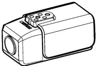
- Lens mount cap
The cap is installed to protect the lens mount section. Remove the lens mount cap before installing a lens (sold separately).
-
Flange-back adjustment dial
-
Flange-back lock screw
-
Camera installation bracket
The bracket can be fixed at the top or bottom of the camera. (page 16)
Part Names and Functions
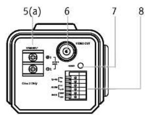

- Power input terminal
a) AC 24 V or DC 12 V input terminal
b) AC 230 V input terminal
- Video output connector (BNC type)
Connect this connector to a device such as a
VCR or monitor with a VIDEO IN connector.
- Power indicator
Comes on when the power to the camera is on.
- External Device Connectors
RS-485 Connector
Connect to an external controller of RS-485 format.
Alarm Output Terminal (ALARM OUT/GND)
Connect to the alarm input of an external
device.
Multi Input Terminal
Connect to an external wired remote control.
Part Names and Functions
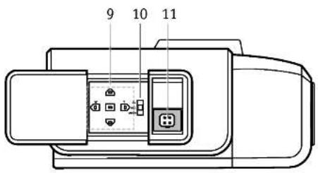
9. Buttons for menu
To set items on the MEMU, use the these buttons on the side panel. (page 17)
10. ALC Lens Setting Switch
DC: When you attach an Auto Iris lens requiring the DC control signal, please put this switch in the DC position.
ELC: When you attach a manual or fixed lens, please put this switch in the ELC position. VIDEO: When you attach an Auto Iris lens requiring the video control signal, please put this switch in the VIDEO position.
11. Lens iris output connector (LENS)
This 4-pin connector is used to send the Iris control signal and power supply to an auto-iris type lens.
LVC-SX703PC AA6ELL ENG 12/8/05 4:51 PM Page 11
Connections

To monitor's Video Input or Camera Input
Basic connection
The peripheral devices (VCR, monitor, lens, etc.), AC adaptor and cables are not supplied.
- Connecting the monitor
Make the video signal connection between the camera and the monitor or time lapse VCR.
- Use a commercially available AC 24 V adaptor.
Connect an AC 24 V power source to the AC 24V input terminal on the back of the camera.
- Insert the plug of this power cord into a wall outlet.
The POWER indicator will light. Adjust the picture on the monitor using the Brightness and Contrast controls etc.
Mounting the Lens


- Remove the lens mount cap from the camera.
- Install the auto-iris lens.
2-1. CS mount type lens
Carefully align the lens mount with the camera opening, then turn the lens slowly to install it.
2-2. C mount type lens
To allow for flange-back adjustment, install the C-mount adaptor (option) on the lens mount, then carefully align the lens mount with the camera opening and turn the lens slowly to install it.
- Connect the lens plug to the lens iris output connector (LENS) on the side of the camera. When using lenses from other makers, the plug shape may not correspond to the terminal on the camera.
In such a case, remove the original plug and using a soldering iron, connect a lens iris plug according to the diagram. (Refer to next page.)
Concerning Auto-Iris Lenses

DC type auto-iris lens
A lens without driver circuit that operates only on a DC power source. In general, this type of lens is referred to as DC type coil lens. (Set the ALC Lens Setting Switch to the DC position.)
VIDEO type auto-iris lens
A lens with amplifier circuit that operates on video signal and DC power source. In general, this type of lens is referred to as EE amplifier type lens.
ALC and LEVEL volume level controls are available on the lens for iris adjustments. (Set the ALC Lens Setting Switch to the VIDEO position.)
CAUTION: Be cautions not to be us Auto Iris Lens with over 50mA.
ELC type auto-iris lens
Use a manual or fixed iris lens (Set the ALC Lens Setting Switch to the ELC position.)
If using a VIDEO type auto-iris lens
- Set the ALC and LEVEL controls on the lens to adjust the iris. Normally the ALC volume should be turned all the way to Av (Average).
- Depending on the type of lens used, the lens may not perform properly. In such a case, adjust the LEVEL volume on the lens casing to correct.
Pin layout for the lens iris output connector

| No. | DC type lenses | VIDEO type lenses |
| 1 | Damp - | Vcc (+12V) |
| 2 | Damp + | Not used |
| 3 | Drive + | Video |
| 4 | Drive - | Ground |
External Device Connections

RS-485 Connection
Connect to an external controller of RS-485 format.
Alarm Connection
Connect an external device such as a buzzer or lamp to the ALARM terminal. When the camera detects motion, the alarm output signal is supplied to the connected external device.
Contact Ratings
• Maximum load current is ±130mA.
- Do not connect any system or device that has over 40 Vp-p (DC 30 V) bias voltage on the contact terminal.

Notes:
Use a relay unit if the voltage or current of the connected device exceeds the ratings.
Multi-Input Connection
Connect an external device to use HOT KEY function. The HOT KEY function is operated when the input signal is "ON". To set the HOT KEY function, see page 35.
The Multi-Input terminal has the register of DC 3.3V pull-up. The sink current must be less than 0.8mA.
OFF: Open contact
ON: Closed contact
Flange-back Adjustment
The adjustment is required only when a lens without focus-adjusting mechanism is mounted, or when a lens with adjusting mechanism is mounted and focus that is more accurate is needed.
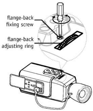
1 Loosen the flange-back fixing screw on the flange-back adjusting ring.
2. Turn the flange-back adjusting ring to obtain a focused point while watching the monitor screen.
3. Tighten the flange-back fixing screw on the flange-back adjusting ring.
Caution:
Tightening the screw by force will cause damage to the screw or deviation of focus.
Note: The object may be out of focus when using a source of near-infrared light than using the visible light.
LVC-SX703PC_AA6ELL_ENG 12/8/05 4:51 PM Page 16
Installation of Camera
The bracket can be installed to either the top of the camera as desired. When changing the position of the camera mounting bracket, you should always reuse the screws that have been removed.
Note:
If using a camera mounting bracket, select a location that is strong enough to bear the full weight of the camera and the mounting bracket for long periods, and install the camera and mounting bracket securely.

natural_image
Line drawing of a mechanical device with attached lever and ports (no text or symbols)
natural_image
Line drawing of a mechanical device with a cylindrical lens and mounting bracket (no text or symbols)LVC-SX703PC_AA6ELL_ENG 12/8/05 4:51 PM Page 17
Menu Operation
This camera utilizes an on-screen user MENU. To set items on the menu, use the following buttons on the side panel.
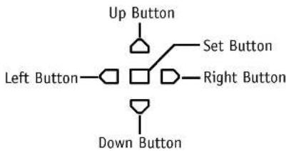
Up button: Moves the cursor upwards. Use this button to select an item or adjust the parameters.
Down button: Moves the cursor downwards. Use this button to select an item or adjust the parameters.
Right button: Moves the cursor to the right. Use this button to select or adjust the parameters of the selected item. The parameter changes each time this button is pressed.
Left button: Moves the cursor to the left. Use this button to select or adjust the parameters of the selected item. The parameter changes each time this button is pressed.
☐ Set button: Executes selections and displays a submenu for an item with the ☑ mark.
LVC-SX703PC AA6ELL ENG 12/8/05 4:51 PM Page 18
Menu Operation
To Open and Exit the Menu screen
Press and hold down □ for 2 seconds or more.
The MENU screen appears on the monitor as shown below. Check the current settings on the menu.
Press and hold down □ for 2 seconds or more to exit the menu screen.
MENU
| LANGUAGE | ENGLISH |
| CAMERA ID | OFF |
| EXPOSURE | |
| WHITE BAL | PUSH AUTO |
| DAY/NIGHT | AUTO |
| MOTION DET | OFF |
| PRIVACY MASK | |
| SPECIAL | |
| INITIAL SET | OFF |
| EXIT |
Language and Camera Identification Settings
MENU
| LANGUAGE | ENGLISH |
| CAMERA ID | OFF |
| EXPOSURE | |
| WHITE BAL | PUSH AUTO |
| DAY/NIGHT | AUTO |
| MOTION DET | OFF |
| PRIVACY MASK | |
| SPECIAL | |
| INITIAL SET | OFF |
| EXIT | -1 |
MENU
| LANGUAGE | ENGLISH |
| CAMERA ID | OFF |
| EXPOSURE | ☑ |
| WHITE BAL | PUSH AUTO |
| DAY/NIGHT | AUTO |
| MOTION DET | OFF |
| PRIVACY MASK | ☑ |
| SPECIAL | ☑ |
| INITIAL SET | OFF |
| EXIT | ☑ |
Language Setting
Select a language for the Setup menu and on-screen display.
- Select [LANGUAGE] option on the [MENU] screen.
- Press left or right button to select a language.
Camera Identification Setting
You can use the camera identification (CAMERA ID) to assign a number to the camera (0 - 255, OFF).
The camera identification's number is displayed on the lower left of the screen. To disappear the number, select [OFF].
- Select [CAMERA ID] option on the [MENU] screen.
- Use □ or □ button to select a ID number of the camera.
LVC-SX703PC AA6ELL ENG 12/8/05 4:51 PM Page 20
Exposure Settings

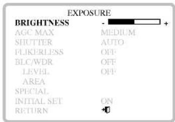
You can set the exposure options using the EXPOSURE menu.
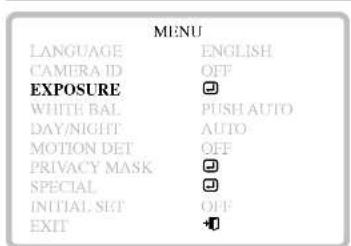
- Select [EXPOSURE] option on the [MENU] screen.
- Press □, □, or □ button and the EXPOSURE menu appears.
- To reset the [EXPOSURE] settings to factory setting, select [INITIAL SET] option then press □ on the [EXPOSURE] menu.
- To return to the previous menu, select [RETURN] option then press □.
Brightness Setting
You can set the brightness level. (7 levels)
- Select [EXPOSURE] option on the [MENU] screen then press □, □, or □ button. The EXPOSURE menu appears.
- Use ▽ or △ button to select [BRIGHTNESS] option.
- Use □ or □ button to set the bright level.
LVC-SX703PC_AA6ELL_ENG 12/8/05 4:51 PM Page 21
Exposure Settings
Automatic Gain Control (AGC) setting
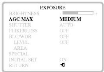
If the images are too dark, change the maximum [AGC] value to make the images lighter.
- Select [EXPOSURE] option on the [MENU] screen then press □, □, or □ button. The EXPOSURE menu appears.
- Use ▽ or △ button to select [AGC MAX] option.
- Use □ or □ button to select a mode. OFF: AGC is not operated. HIGH: Applies AGC with high-level. MEDIUM: Applies AGC with middle-level. LOW: Applies AGC with low-level.
LVC-SX703PC_AA6ELL_ENG 12/8/05 4:51 PM Page 22
Exposure Settings


Shutter Speed Setting (SHUTTER)
Note: When [FLICKERLESS] option is set to [ON] on the [EXPOSURE] menu, this item is not available.
- Select [EXPOSURE] option on the [MENU] screen then press □, ▽, or ▽ button. The EXPOSURE menu appears.
- Use ▽ or △ button to select [SHUTTER] option.
- Use □ or □ button to set shutter speed. (AUTO, AUTO X2 - X320, FIX X2 - X320, 1/50 - 1/50000)
Flickerless Setting (FLIKERLESS)
Use for removing the flicker of picture.
- Select [EXPOSURE] option on the [MENU] screen then press □, ▽, or ▶ button. The EXPOSURE menu appears.
- Use ▽ or △ button to select [FLICKERLESS] option.
- Use □ or □ button to set between [ON] or [OFF]. Set to [ON] to remove the flicker.
LVC-SX703PC AA6ELL ENG 12/8/05 4:51 PM Page 23
Exposure Settings

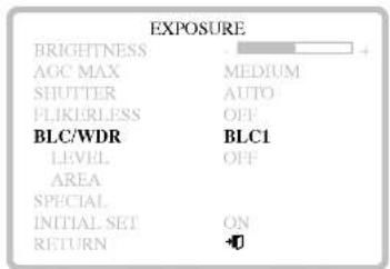
You can set the exposure options using the [EXPOSURE] menu.
BLC/WDR Setting
Use [BLC/WDR] option to set the options for BLC or WDR camera.
- Select [EXPOSURE] option on the [MENU] screen then press □, □, or □ button. The EXPOSURE menu appears.
- Use ▽ or △ button to select [BLC/WDR] option.
- Use □ or □ button to select a mode. (BLC1, BLC2, USER, WDR, OFF)
BLC 1 - 2 (Auto back light compensation): If you use an ordinary camera when there is an intense and concentrated illumination behind an object, the back light will shade the image on the monitor screen. The BLC function prevents such a back light effect to secure a clear image under all illumination environments.
(Continued →)
LVC-SX703PC AA6ELL ENG 12/8/05 4:51 PM Page 24
Exposure Settings
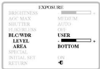

USER: You can use the user setting for BLC level and BLC area.
- LEVEL: Select a user BLC level to prevent such a back light effect to secure a clear image.
- AREA: Select a user area to prevent such a back light effect to secure a clear image. (BOTTOM, TOP, LEFT, RIGHT, and CENTER.)
WDR: The WDR camera is state of the art to enlarge the screen profit effectively, especially for taking photos of a window in a building. In short it revives both the indoor and outdoor status as they are clearly.
White Balance Settings
| MENU | |
| LANGUAGE | ENGLISH |
| CAMERA ID | OFF |
| EXPOSURE | |
| WHITE BAL | PUSH AUTO |
| DAY/NIGHT | AUTO |
| MOTION DET | OFF |
| PRIVACY MASK | |
| SPECIAL | |
| INITIAL SET | OFF |
| EXIT | |
| WHITE BALANCE | |
| WB MODE | ATW |
| RED ADJ | |
| BLUE ADJ | |
| INITIAL SET | ON |
| RETURN | 0 |
You can set the white balance options using the [WHITE BALANCE] menu.
- Select [WHITE BAL] option on the [MENU] screen.
- Press □, ▽, or ▶ button and the WHITE BALANCE menu appears.
- To reset the [WHITE BALANCE] settings to factory setting, select [INITIAL SET] option then press □ on the [WHITE BALANCE] menu.
- To return to the previous menu, select [RETURN] option then press □.
White Balance Settings
MENU
| LANGUAGE | ENGLISH |
| CAMERA ID | OFF |
| EXPOSURE | |
| WHITE BAL | ATW |
| DAY/NIGHT | AUTO |
| MOTION DET | OFF |
| PRIVACY MASK | |
| SPECIAL | |
| INITIAL SET | OFF |
| EXIT |
WHITE BALANCE
| WB MODE | ATW |
| RED ADJ | |
| BLUE ADJ | |
| INITIAL SET | ON |
| RETURN | +0 |
Setting the WB (White Balance) Mode
You can select one of three modes for white balance adjustment as follows:
-
Select [WHITE BALANCE] option on the [MENU] screen then press □, □, or □ button. The WHITE BALANCE menu appears.
-
Use ▽ or △ button to select [WB MODE] option.
-
Use □ or □ button to select one of three modes for white balance.
ATW (Auto-Tracing White Balance): In this mode, the color temperature is monitored continuously and thereby white balance is automatically set. The color temperature range for the proper white balance is approximately 2 500 - 9 500K. Proper white balance may not be obtained under the following conditions:
1) The color temperature is out of the 2 500 - 9 500K range.
2) When the scene contains mostly high color temperature objects, such as a blue sky or sunset.
3) When the scene is dim.
(Continued →)
LVC-SX703PC AA6ELL ENG 12/8/05 4:51 PM Page 27
White Balance Settings
WHITE BALANCE
WB MODE
RED ADJ
BLUEADI
INITIAL SET
RETURN

PUSH AUTO: If you select the PUSH AUTO mode in the WHITE BALANCE menu, you will be able to set up the White Balance automatically using □ button; press and hold □ button then release.
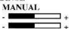
MANUAL: You can set the white balance options manually.
- RED ADJ: Obtains the optimum amount of red gain.
- BLUE ADJ: Obtains the optimum amount of blue gain.
WHITE BALANCE
WB MODE
RED ADJ
BLUE ADJ
INITIAL SET
RETURN

LVC-SX703PC_AA6ELL_ENG 12/8/05 4:51 PM Page 28
Day/Night Setting
| MENU | |
| LANGUAGE | ENGLISH |
| CAMERA ID | OFF |
| EXPOSURE | |
| WHITE BAL | ATW |
| DAY/NIGHT | AUTO |
| MOTION DET | OFF |
| PRIVACY MASK | |
| SPECIAL | |
| INITIAL SET | OFF |
| EXIT | |
It is a function of a color camera to delete the filter with the IR Cut function in an illumination below the standard value so that it has a better sensitivity.
- Select [DAY/NIGHT] option on the [MENU] screen.
- Use □ or □ button to select one of four modes for day/night function.
AUTO: The camera selects black and white mode if the picture is dark, or color mode if the picture is bright enough.
EXT : Switches between color picture and black-and-white picture when an external day/night switching signal is received.
NIGHT: Black-and-white mode enabled.
DAY: Color mode enabled.
Note:
The AUTO mode is not available if AGC mode is set to [OFF] or SHUTTER mode is set to a fixed mode.
Motion Detector Setting (MOTION DET)


The motion detector detects the moving objects in the scene by monitoring changes in brightness level. You can select the level of sensitivity for motion detection.
When this camera is connected to a compatible intelligent CCTV system, the camera transmits an alarm signal by multiplexing it with the video signal.
- Select [MOTION DET] option on the [MENU] screen.
- Press □, ▽, or ▷ button and the MOTION DETECT menu appears.
- Use [SENSITIVITY] option to obtain the optimum detection level (7 levels).
- Use [AREA] option to select an area for motion detection.
- To reset the [MOTION DETECT] settings to factory setting, select [INITIAL SET] option then press □ on the [MOTION DETECT] menu.
- To return to the previous menu, select [RETURN] option then press □.
Motion Detector Setting (MOTION DET)
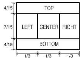
Detection Area
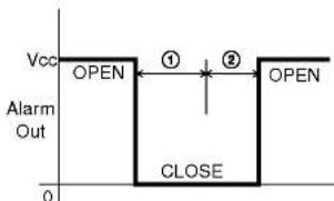
- The period of motion.
- The hold time is 1 sec.
This camera has an alarm function. When the picture changes, the internal switch is closed.
- Sensitivity
Motion is detected when the accumulated value of changed brightness level exceeds 10% (MEDIUM mode) of reference in more than one area.
- Condition
The alarm function performs after 10 seconds when the camera is turned on.
- Caution
Motion detection malfunctions under the following situations. Please note the conditions below.
If shooting an object under flickering fluorescent.
- If leaves or curtains are swayed by the wind.
- Alarm keep low for 1 second after the end of moving picture.
- This function which is Motion Detection & Sensitivity has not been evaluated by UL.
Privacy Masking Setting
| MENU | |
| LANGUAGE | ENGLISH |
| CAMERA ID | OFF |
| EXPOSURE | ☐ |
| WHITE BAL | ATW |
| DAY/NIGHT | AUTO |
| MOTION DET | OFF |
| PRIVACY MASK | ☐ |
| SPECIAL | ☐ |
| PRIVACY MASKING | |
| PRIVACY-1 | OFF |
| PRIVACY-2 | OFF |
| PRIVACY-3 | OFF |
| PRIVACY-4 | OFF |
| PRIVACY-5 | OUT |
| MASK ADJUST | |
| H POSITION | ☐ ☐ |
| V POSITION | ☐ ☐ |
| H SIZE | ☐ ☐ |
| V SIZE | ☐ ☐ |
| RETURN | ☐ |
This function is aiming at the protection of personal privacy, selecting a screen part black not to be displayed in the screen. This function permits the control of the strength level in 8 levels. You may setup the size and location of the area.
- Select [PRIVACY MASK] option on the [MENU] screen.
- Press □, ▽, or ▶ button and the PRIVACY MASKING menu appears.
- Use ▽ or △ button to select a privacy number then press □, □, or ▽ button. The MASK ADJUST menu appears.
- Use ▽ or △ to select an option then use □, or □ button to adjust the option.
• H POSITION: Moves height position of the mask.
• V POSITION: Moves vertical position of the mask.
- H SIZE: Enlarge or increase the height size of the mask.
• V SIZE: Enlarge or increase the vertical size of the mask.
- To return to the previous menu, select [RETURN] option then press □.
Special Menu Settings

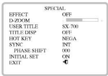
This menu lets you adjust and set up EFFECT, D-ZOOM, USER TITLE, TITLE DISP, and SYNC function by yourself in the SPECIAL menu.
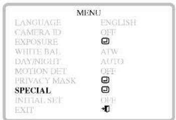
- Select [SPECIAL] option on the [MENU] screen.
- Press □, □, or □ button and the SPECIAL menu appears.
- Use ▽ or △ to select an option then use □, or □ button to adjust the option.
- To reset the [MOTION DETECT] settings to factory setting, select [INITIAL SET] option then press □ on the [MOTION DETECT] menu.
- To return to the previous menu, select [RETURN] option then press □.
Special Menu Settings


Setting the digital effect (EFFECT)
You can select the digital effect.
- Select [SPECIAL] option on the [MENU] screen.
- Press □, ▽, or ▷ button and the SPECIAL menu appears.
- Use ▽ or △ to select [EFFECT] option
- Use □ or □ button to select a digital effect.
• [NEGA]: Turn on the negative effect.
• [B/W]: The picture will be displayed with grayscale.
• [V-FLIP]: Flip the picture vertically.
• [MIRROR]: Turn on the mirror effect.
• [ROTATE]: Rotate the picture. (180°)
• [FREEZE]: Freeze the picture.
• [OFF]: Turn off the digital effect.
Special Menu Settings
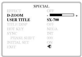
Setting the digital zoom (D-ZOOM)
You can select the digital zoom level. This function is not available when the BLC/WDR option is set to WDR or EFFECT option is set to FREEZE.
- Select [SPECIAL] option on the [MENU] screen.
- Press □, □, or □ button and the SPECIAL menu appears.
- Use ▽ or △ to select [D-ZOOM] option
- Use □ or □ button to select a digital zoom level (7 level).
Naming the camera (USER-TITLE)
You can name the camera independently.
- Follow steps 1-2 as shown above.
- Use ▽ or △ to select [USER TITLE] option The first character of the name will blink.
- Use □ or □ button to select a character for the first character then press □ button. The second character blink.
- Repeat step 3 to set the remain characters.
Special Menu Settings


Setting the title display
The onscreen display of camera's name can be turned on or off.
- Select [SPECIAL] option on the [MENU] screen.
- Press □, △, or ▷ button and the SPECIAL menu appears.
- Use ▽ or △ to select [TITLE DISP] option
- Use □ or □ button to select [ON] or [OFF].
Set to [ON] and the camera's name appears on the screen.
Setting the HOT KEY
You can set the HOT KEY function for signal from MULTI INPUT terminal. This function is fixed to [DAY/NIGHT] when DAY/NIGHT option is set to [EXT].
- Follow steps 1-2 as shown above.
- Use ▽ or △ to select [TITLE DISP] option
- Use □ or □ button to select a function.
(NEGA, B/W, V-FLIP, MIRROR, ROTATE, FREEZE, or OFF)
Special Menu Settings

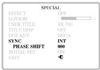
Synchronization Setting (SYNC)
You can select internal sync (INT) mode or line-lock (LINE) mode. The SYNC function is available only with AC power source.
- Select [SPECIAL] option on the [MENU] screen.
- Press □, □, or □ button and the SPECIAL menu appears.
- Use ▽ or △ to select [SYNC] option.
- Use ☐ or ☐ button to select [INT] or [LL] (Line Lock). [INT]: Selects for using the internal synchronization. [LL] (Line Lock): Selects for the operation of multi cameras because it synchronizes the camera phase by using the external signal (AC Signal). A little phase deviation for some sets may be aligned.
- Use ▽ or △ to select [PHASE SHIFT] option.
- Use □ or □ button to select phase range. The PHASE ranges are from 0 to 624.
RS-485 Protocol
Data Communication Format
• Data Length: 1 Byte (8 Bit)
- Start/Stop Bit: 1 BIT
- Parity Bit: None
• Baud rate: 9,600 bps
Format
| BYTE 1 | BYTE 2 | BYTE 3 | BYTE 4 | BYTE 5 | BYTE 6 |
| 0xC5 | CODE1 | CODE2 | CODE3 | CAM_ID | *C.S. |
*C.S. = Check Sum
- The data of total 6 bytes is transmitted from the external RS-485 device to the camera.
- BYTE 6: The value of Check Sum from 'BYTE 1' to 'BYTE 5'.
ex) In case of transmission, 0xC5, 0x5F, 0x02, 0x00, 0x0A" C.S. = 0xC5 + 0x5F + 0x02 + 0x00 + 0x0A = 0x0130 therefore, C.S. = 0x30
Commands
| Function | Command(external device → camera) |
| OSD Menu ON/OFF | 0xC5, 0x5F, 0x25, 0x00, ID, C.S. |
| LEFT Button | 0xC5, 0x5F, 0x38, 0x00, ID, C.S. |
| Right Button | 0xC5, 0x5F, 0x39, 0x00, ID, C.S. |
| Up Button | 0xC5, 0x5F, 0x02, 0x00, ID, C.S. |
| Down Button | 0xC5, 0x5F, 0x04, 0x00, ID, C.S. |
| Menu Button | 0xC5, 0x5F, 0x24, 0x00, ID, C.S. |
- You must send "Stop" command to camera after sending each command described above. The "Stop" command is "0xC5, 0x5F, 0x0C, 0x00, ID, C.S.".
Specifications
| Total/Effective Pixels | 470K/440K Pixels |
| Pick-up Device | 1/3" Interline Color CCD |
| Lens | C/CS Mount |
| Iris | DC/ELC/VIDEO Selectable |
| Signal Process | Digital Signal Process |
| Scanning System | 2:1 Interface |
| Synchronization System | Internal/Line Lock |
| Scanning Frequency | 50 Hz (VD) |
| Resolution | 540 Lines |
| S/N Ratio | More than 52 dB (AGC Off) |
| Standard Illuminance(1/3 Video Output) | Day: 0.001 (0.3: DSS Off) LuxNight: 0.0001 (0.02: DSS Off) Lux |
| Video Output Signal | 1.0 Vp-p Composite Signal (75 Ω) |
| Auto Gain Control | Off/Low/Medium/High |
| Exposure | Automatic Control with DC/Video Iris meter/ Electronic Light |
LVC-SX703PC AA6ELL ENG 12/8/05 4:51 PM Page 39
Specifications
| Electric Shutter | 1/50 - 1/100,000 (Auto Mode) |
| White Balance | ATW/PUSH AUTO/MANUAL |
| Back Light | OFF/BLC1/BLC2/USER/WDR |
| Motion Detection: | OFF/ON (Area, Sensitivity) |
| Power Consumption | Less than 6W |
| Operation Temperature | -10°C - 50°C (Humidity: 0%RH - 80%RH) |
| Storage Temperature | -20°C - 60°C (Humidity: 0%RH - 85%RH) |
| Weight | 250g |
| Dimension (H x V x D) | 67.1 x 59 x 127.5 mm |
LVC-SX703PC AA6ELL ENG 12/8/05 4:51 PM Page 40

LG Electronics Inc.
P/NO : 3834RS0075R

- Color Video Camera Instruction Manual
- CAUTION
- RISK OF ELECTRIC SHOCK DO NOT OPEN
- Regulatory Notices For U.S.A
- Important Safety Instructions
- Contents and Features
- Contents
- Features
- Features Chart
- Cautions for Safe Operation
- Power Supply
- Handling of the unit
- Operating and storage location
- Part Names and Functions
- Buttons for menu
- ALC Lens Setting Switch
- Lens iris output connector (LENS)
- Connections
- Basic connection
- Mounting the Lens
- 2-1. CS mount type lens
- 2-2. C mount type lens
- Concerning Auto-Iris Lenses
- DC type auto-iris lens
- VIDEO type auto-iris lens
- ELC type auto-iris lens
- If using a VIDEO type auto-iris lens
- Pin layout for the lens iris output connector
- External Device Connections
- RS-485 Connection
- Alarm Connection
- Contact Ratings
- Notes:
- Multi-Input Connection
- Flange-back Adjustment
- Caution:
- Installation of Camera
- Note:
- Menu Operation
- To Open and Exit the Menu screen
- Language and Camera Identification Settings
- Language Setting
- Camera Identification Setting
- Exposure Settings
- Brightness Setting
- Automatic Gain Control (AGC) setting
- Shutter Speed Setting (SHUTTER)
- Flickerless Setting (FLIKERLESS)
- BLC/WDR Setting
- White Balance Settings
- Setting the WB (White Balance) Mode
- Day/Night Setting
- Motion Detector Setting (MOTION DET)
- - Sensitivity
- - Condition
- - Caution
- Privacy Masking Setting
- Special Menu Settings
- Setting the digital effect (EFFECT)
- Setting the digital zoom (D-ZOOM)
- Naming the camera (USER-TITLE)
- Setting the title display
- Setting the HOT KEY
- Synchronization Setting (SYNC)
- RS-485 Protocol
- Data Communication Format
- LG Electronics Inc.
Merek : LG
Model : LVC-SX703MC
Kategori : 1027