BCC - 17756 ART - Panduan pengguna gratis
Temukan panduan perangkat secara gratis BCC ART dalam format PDF.

Pertanyaan pengguna tentang BCC ART
0 pertanyaan tentang perangkat ini. Jawab yang Anda tahu atau ajukan milik Anda sendiri.
Ajukan pertanyaan baru tentang perangkat ini
Unduh instruksi untuk 17756 dalam format PDF gratis! Temukan panduan Anda BCC - ART dan ambil kembali perangkat elektronik Anda. Di halaman ini diterbitkan semua dokumen yang diperlukan untuk penggunaan perangkat Anda. BCC merek ART.
PANDUAN PENGGUNA BCC ART
105
BASS COMMAND CENTER
BCC

USER'S GUIDE
BCC
Introduction
Thank you for purchasing a BCC (Bass Command Center)—and congratulations. You now own one of the most sophisticated pieces of audio signal-processing technology available. Offering a level of processing resolution and sound quality of rack-mountable units that can cost thousands of dollars more, the BCC uses specially designed integrated circuits and a straightforward user interface that quickly and easily gives you access to all of its features. In addition, it puts all of this impressive processing power at your feet—literally. All of the BCC's programs can be recalled via the footswitch pads, an external-control jack lets you manipulate volume, wah, and other functions with an optional footpedal, and you can even make program changes in remote gear via MIDI.
Features
- 8 Distortion types
- Compressor
• 5-band EQ - Flanger
- Chorus
- Panner/Tremolo
- Pitch Shifter
- Digital Delay
• Digital Reverb - Sub Bass & Presence boost/cut
• 50 presets - Stereo outputs
- Easy programming
• MIDI Out for controlling external gear
• Programmable external control pedal jack
• Programmable Effects Loop - Externally controllable built-in wah-wah and volume
• Headphone output
• Designed and manufactured in the United States of America


ART's BCC provides you with 13 of the finest effects, including compression, distortion, EQ, flanging, chorusing, panning, tremolo, pitch shifting, delay, reverb, noise gate, wah-wah, and amp simulation. It operates in mono or in stereo, taking mono inputs and creating spacious stereo sounds, plus it's incredibly simple to use. ART designed a combination of powerful processing and ease of use into the BCC. We strongly suggest that you read and refer to this manual while getting used to your new processor.
We'd like to extend special thanks to Bernard "Bunny" Brunel for his guidance while we were designing the BCC. One of the finest bassists in rock and jazz (known for his phenomenal bassmanship on his solo projects, his popular instructional books, and his fiery work alongside Chick Corea and Kazumi Watanabe, among others), Bunny helped ART develop the features and sounds that give you an immense range of tone-shaping functions that brings out the best in your bass—and your playing.
Fill in the following information for your reference:
DATE OF PURCHASE
PURCHASED FROM
SERIAL NUMBER
105-5004-101


QUICK START INSTRUCTIONS
You've unpacked your BCC and you're in a hurry to get it up and running. You probably would rather play with it than read the manual (at least, right now). Fair enough. But check out the basics, outlined here, just to get your BCC on line. It should take only a couple of minutes for you to read through them, and then you'll be ready to fire up your BCC. Refer to this section if you have any difficulty. And later, when you want to get into more of the details of your BCC, check out the rest of the manual.
Quick Setup
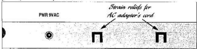
Insert the supplied AC adapter's plug into the input labeled Power on the BCC's back panel. Loop the AC adapter's cable through the two strain reliefs on the back panel (see diagram on page 8).
Turn the Output knob to its full counterclockwise position. Turn this knob up only after all other setup steps are completed.
Straight into an amp: If you're patching the BCC into a bass (or other instrument) amplifier, use one cord between the instrument and the BCC's Input. Run a second cord from the Left Out to the amp's input. If the amp has stereo input capabilities (or if you're using two amps), connect another cord between the BCC's Right Out and the amp's second-channel input (or the second amp's input).
In an amp's effects loop: If you're patching the BCC into a bass (or other instrument) amplifier's effects loop, and it's mono, use one cord between the amp's effects send jack and the BCC's Input. Run a second cord from the Left Out to the amp's effects return jack. (If the amp has stereo returns, use another cord to connect the BCC's Right Out to the amp's other effects return jack.)
With a mixer: Connect a cord with 1/4" plugs between your mixer's


reverb send and the BCC's Input. Connect one more cord between the BCC's Left Out and the mixer's reverb return jack. If the mixer has a second reverb return, connect a cord from the BCC's Right Out to that second return. You can also patch the BCC into a channel's insert loop; follow the same procedure.
Note: If you need further help doing your initial hook-up, refer to the diagrams and information on pages 33 through 39.
Plug the BCC's AC adapter into the wall socket (the BCC is now powered up). Now turn on your mixer or amp and your monitor amplifier.
Make sure that your bass' volume control, or your mixer's or amp's send level control is turned up and that signal is being sent to the BCC. Turn the BCC's Output knob clockwise to its midpoint (12 o'clock), or until you hear sound coming out of your amp or monitors.
Setting The Input Level
Because every instrument has a different amount of output (active pickups vs. passive pickups, single-coils vs. humbuckers, etc.), you should set the BCC's input level to match your instrument. This ensures the best signal-to-noise ratio and gets the most out of the effects. Follow this procedure:
- Push the Bypass footswitch. (Setting the level with the BCC in Bypass mode will optimize its performance.)
- Push the footswitch labeled Mode.
- Push the switch labeled Param.
- Turn the Encoder knob until the LED along the top row of the indicator matrix labeled MIDI/Util glows, as well as the Param LED (on the far left side of the indicator matrix) labeled with the number 1.
- Push the Value button (the LED above it glows and a number between 1 and 8 appears in the Numeric Display).
• Starting at the number 1 position, while playing reasonably hard on

your instrument turn the Encoder knob clockwise until the Clip LED glows occasionally. If the BCC's Clip LED glows constantly, turn down the instrument's output level and/or lower the BCC's input level. Remember, the Clip LED should only glow when a really loud instantaneous signal reaches the BCC.
- Once you've set a good input level, press the Mode switch. The input level is automatically saved in the BCC's memory.
Note: The Input Level setting is global, meaning that it affects the input at all times, regardless of which preset is activated.
Now turn up the BCC's Output level, and raise the gain or return level on your amp or mixer. You should be hearing the BCC's effect. If not, check your connections and your amp or monitor system (you did remember to turn it on, didn't you?).
Select program banks with the Down and Up footswitches and Presets within those banks by stepping on any of the footswitches labeled One through Five. You can also bypass the BCC's circuitry by stepping on the Bypass footswitch. For a complete list of the factory presets, arranged according to bank and number, see page 42.
Give your bass a real workout. Mix your entire album. Try all of the presets, and don't hold back. Then, when you're ready, check out the rest of this manual for all the details on how to get the most out of your BCC.


INSTALLATION
The BCC may be used in a variety of setups including: straight into a bass, P.A., or other amplifier, into a mixing console, and in the effects loop of an instrument or P.A. amplifier. Self-contained in an all-steel enclosure, the BCC is designed for continuous professional use and can withstand the rigors of the road and stage.
Powering The BCC
The BCC is powered by an external AC adapter. Always make sure that its output jack is securely plugged into the rear of the BCC, and that the adapter is held firmly in an electrical outlet. After inserting the AC adapter's plug into the BCC's Power 9VAC jack, loop part of its cable through each of the strain-relief tabs (the square cutouts with a "tongue") cut into the unit's rear, as shown in this illustration:
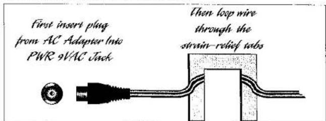
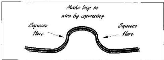
To wrap the wire through each of the cutouts, flex the wire into a loop like this, and then slip it over the tongue of the cutout:

Never operate the BCC or AC adapter in the rain or in wet locations. If the AC adapter's cord is ever cut or damaged, discontinue using it and replace the adapter with a new one. To prolong its life, unplug the adapter when the BCC is not in use. Alternatively, if the BCC's AC adapter is mounted in a rack, plug the adapter into a switched power strip so that you can conveniently turn it off with your other gear. Refer to the label on the adapter for proper operating voltages.
BCC FRONT-PANEL CONTROLS & INDICATORS
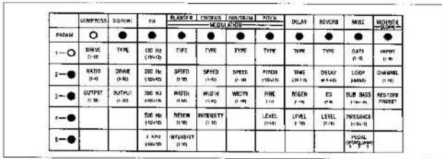
The effects are arranged in vertical rows on the large matrix that fills the left half of the BCC's front panel. The Compressor, Distortion, and EQ are analog effects, while the Modulation Effects (Flanger, Chorus, Panner/Tremolo, and Pitch Shifter), Delay, and Reverb are digital. Other less apparent, yet equally important, effects include the Sub Bass and Presence EQ enhancers and Pedal. Think of the arrangement as Effects, Miscellaneous Effects & Control Functions, and MIDI/Utility Functions.
Parameters are arranged vertically in this row
Effects and control, utility, and MIDI functions are arranged in vertical rows from left to right
| COMPRESO | DISTORT | EQ | FLUERER | CHOPOLI | TAWTHRM | RTOQ | DILAY | REVIEW | NIS | MOUNT | |
| MODULATION | |||||||||||
| PANNA | ○ | ○ | ○ | ○ | ○ | ○ | ○ | ○ | ○ | ○ | ○ |
| 1—○ | DRIVE(3-12) | TYPE | 100 Kg(30-120) | TYPE | TYPE | TYPE | TYPE | TYPE | TYPE | GATI(1-12) | INPUT(1-6) |
| 2—○ | RATIO(4-8) | DRIVE(1-12) | 250 Kg(30-120) | SPEED(1-8) | SPEED(1-8) | SPEED(1-8) | RITCH(10-120) | TIME(10-120) | GRAY(2-120) | LOOP(30-27) | CHANNEL(1-12) |
| 3—○ | RUNSHIP(4-25) | RUNSHIP(1-20) | 350 Kg(30-120) | WIDTH(1-8) | WIDTH(1-8) | WIDTH(1-8) | FINE(1-2) | RIKEN(1-2) | EX | SUB ROUND(10-120) | RESTONE(PRESS) |
| 4—○ | 800 Kg(30-120) | REMEN(1-8) | INTERENSITY(1-8) | LEVEL(1-9) | LIVEL(1-9) | LEVEL(1-10) | PREFERENCE(10-120) | ||||
| 5—○ | 3 MHz(30-120) | INTERENSITY(1-8) | PEGRAL(10-120) | ||||||||


For each effect listed below, every Parameter is given along with its range of Values (shown in parenthesis).
ANALOG EFFECTS SECTION
Compressor
Drive (1-12)
Ratio (1-4)
Output (1-32)
A compressor squeezes the dynamic range of a sound, making louder sounds quieter and quieter sounds louder. This is useful for bringing out harmonics on a bass, or increasing sustain. Extreme compression ratios can have the side effect of increasing the apparent noise in a signal, so start with lower ratios (a ratio of 1:1 means no compression; however, you can use the Compressor's Drive and Output to adjust the level going to subsequent effects stages). Experiment with various Drive and Ratio settings to find the best balance of compression and lowest noise. The Limit setting (4) is useful for limiting the dynamic range of extremely dynamic funk styles, where snapping and popping create brief, sharp increases in level that can lead to unwanted distortion
The Drive Parameter sets the intensity of the signal being fed into the Compressor's circuitry.
The compression Ratio sets the amount of compression. The Ratios you can select (1-4) are as follows:
| Displayed | Ratio |
| 1 | 1:1 (Bypass) |
| 2 | 1.5:1 |
| 3 | 4:1 |
| 4 | Limit |
The Compressor's output level is adjustable from 1 to 32, with 32 being the maximum output level.


Note: For overall best dynamic range, set the Compressor's Output to match the level you get when the BCC is in Bypass mode.
Distortion
Type (1-8)
Drive (1-32)
Output (1-32)
The BCC provides you with nine different distortion types, each with its own personality. Classic and modern overdrive and distortion sounds are available to be used as-is, or modified to suit your musical needs. Note that selecting type "1" places the distortion in bypass mode (no distortion, input goes straight through to the output of the distortion section).
Displayed Type
| 1 | Bypass |
| 2 | Bright Rock |
| 3 | Bright Rock Boost |
| 4 | Straight Rock |
| 5 | Bright Screamer |
| 6 | Bright Boost Screamer |
| 7 | Overdrive 1 |
| 8 | Overdrive 2 |
The Drive control determines how hard the incoming signal drives the distortion section. Extremely low Drive settings and extremely high Output settings may create noticeable noise. Therefore, experiment with the best balance of Drive and Output settings in combination.
The Distortion's output level is adjustable from 1 to 32, with 32 being the maximum output level. Note: For overall best dynamic range, set the Distortion's Output to match the level you get when the BCC is in Bypass mode.


EQ
100 Hz (-12/+12)
250 Hz (-12/+12)
350 Hz (-12/+12)
500 Hz (-12/+12)
3 kHz (-12/+12)
This 5-band graphic equalizer allows you to fine-tune your sound. Each band is its own Parameter, and Values are adjustable in 2dB increments from -12dB (maximum cut) to +12dB (maximum boost).
At the "0" (zero) setting for any band, there's no boost or cut in that frequency range. Therefore the input and output signal in that frequency range are identical.
MODULATED EFFECTS SECTION
This digital section includes Flanger, Chorus, Panner/Tremolo, and Pitch Transposer (indicated in the Numeric Display as FLA, cho, trE, and Pit). No more than one Modulated Effect may be used in any Preset.
Flanger
| Type | 1 | Normal (Mono) |
| 2 | Inverted (Mono) | |
| 3 | Normal, Stereo | |
| 4 | Inverted, Stereo |
Speed (1-16)
Width (1-16)
Regen (1-16)
Intensity (1-10)
Flanging creates an airy, swooshing sound that can range from subdued and compelling to absolutely ferocious. Four different Flanger types are available in the BCC, each a variation on the primary flanging sound.


The Normal (Type 1) flanging sound is designed for mono applications, as is the Inverted (Type 2) flanger, in which the flanged signal has been inverted 180 degrees out of phase with the original signal.
The two remaining flanging types require using both outputs in stereo. Type 3, Normal Stereo, is the same as Type 1, except that the signal is spread in stereo and moves from left to right. Type 4 is the same as Type 3, but is inverted. Note: If only the Left Out (mono) is used, then the effects from both channels will combine and cancel each other.
Speed is adjustable from 1 (slowest) to 16 (fastest).
Width is adjustable from 1 (least effect) to 16 (heaviest effect).
Regeneration (feedback, or recycling of the output back into the input for increased effect) is adjustable from 1 (minimum) to 16 (maximum).
Note: Extremely high settings of both Regen and Width can create undesirable feedback—approach the maximum settings of these Parameters with care.
Intensity sets how prominent the Flanger's effect is, with 1 being the minimum and 10 being the maximum.
Chorus
| Type | 1 | Normal (Mono) |
| 2 | Inverted (Stereo) | |
| 3 | Analog (Classic) |
Speed (1-16)
Width (1-16)
Intensity (1-10)
Chorusing is a splitting of the input signal and detuning of one part before recombining it with the other signal, thereby producing a thicker texture akin to doubling or adding multiple instruments in unison. Three different Chorus types are available. The Normal (Type 1) Chorus sound


is designed for mono applications, while the Inverted (Type 2) Chorus inverts one signal 180 degrees out of phase with the other so that the most spacious effect is produced in Stereo.
The remaining Chorus type is Analog, or Classic, which (as its name suggests) sounds like the thick, lush analog choruses from the early days of chorusing. Its output reaches the Left Out and Right Out 180 degrees out of phase with each other for a wide stereo effect.
Note: When only the Left Out is used, the outputs are combined and become mono, cancelling the effect.
Speed is adjustable from 1 (slowest) to 16 (fastest).
Width is adjustable from 1 (least effect) to 16 (heaviest effect).
Intensity sets how prominent the Chorus' effect is, with 1 being the minimum and 10 being the maximum.
Panner/Tremolo
Type trE
PAn
Speed (1-16)
Width (1-16)
Type PAn and Type trE select Panner and Tremolo, two classic effects that create movement in sounds. The Panner spreads the signal between the left and right outputs, while the Tremolo is a cyclical increasing and decreasing of the sound.
Speed is adjustable from 1 (slowest) to 16 (fastest).
Width is adjustable from 1 (least effect) to 16 (heaviest effect).
Note: When only the Left Out is used in Panner mode, the Left and Right signals combine and cancel each other.


Pitch Shifter
Type on
Pitch (-12/+12)
Fine (-15/+15)
Level (1-16)
The Pitch Shifter raises or lowers a pitch to create harmonies, or to detune a sound. (Detuning of the sound by small increments can create a chorus-like effect.) Note: 'There are no Type options for the Pitch Shifter; therefore, when it is selected, the Type always shows as "on," regardless of whether you try changing the Value.
The Pitch Parameter lets you select any semitone interval from a unison (0, or zero) to one octave up (+12) or one octave down (-12).
The Fine range is ±1 half-step. There is a 0 value, meaning no fine tuning up or down, and there are 15 up values and 15 down values for detuning. Each increment is equal to approximately 6 cents (6/100 of a semitone) of pitch change.
DIGITAL EFFECTS SECTION
Delay
Type 1 Mono
2 Analog (Mono)
3 Ping Pong (Stereo)
Time (10ms-1000ms)
Regen (1-16)
Level (1-16)
There are three types of delays in the BCC, each with its own personality. Type 1 (Mono) is a straight-ahead repeat of the input signal. Type 2 mimics the characteristics of analog or tape echoes, in that the frequency


response range is limited and each repeat has less treble. Type 3 spreads each delay across the stereo spectrum, sending each alternate echo to the left output and then the right output.
Delay time is adjustable in the following increments:
| Range | Increment |
| 10-60ms | 5ms |
| 70-400ms | 10ms |
| 425-800m | 25ms |
| 850-1000ms (1 sec) | 50ms |
Regeneration (feedback, or recycling of the output back into the input for increased effect) is adjustable from 1 (minimum) to 16 (maximum).
Level sets the amount of delayed effect relative to the incoming signal (1 is minimum, 16 is maximum).
Reverb
Type 1 Room 2 Hall
Decay (0.2-4.0 sec in 0.2 sec increments)
EQ (1-8)
Level (1-16)
There are two types of Reverb in the BCC, Room and Hall. A Room is a simulation of a large room such as a ballroom or a nightclub. A Hall is a simulation of an auditorium-sized building's interior. These reverbs produce a stereo image when both outputs are used.
Decay sets the amount of time that it takes for the reverb to die away (adjustable from 0.2 seconds to 4.0 seconds).
EQ lets you tailor the reverb's brightness according to your taste (1 is brightest, and 8 is darkest).


Level sets the amount of reverb effect relative to the incoming signal (1 is minimum, 16 is maximum).
Stereo Operation
The BCC is designed for use in mono or stereo. When both outputs are used, the signal from the last active effect in the digital effects section is in stereo. (All other effects prior to the final digital effect are then automatically placed in mono.) If the Delay is not the final digital effect and Ping Pong (Type 3) is selected, then the Delay's outputs are automatically summed to mono, creating a two-tap mono delay.
OTHER EFFECTS
Misc (Miscellaneous)
Gate (1-13)
Loop (out, in)
Sub Bass (-12/+12)
Presence (-12/+12)
Pedal (1, 2, 3)
The Gate is a signal, or noise, gate that opens when signals exceeding the threshold level are present. It can be set individually for each Preset. The Gate Parameter sets this threshold (1 is the lowest threshold, 13 the highest). The Gate is especially useful in removing noise between notes or when you aren't playing—particularly if a lot of distortion is used, or if your bass has single-coil pickups.
The Loop In/Out Parameter lets you select whether the effects loop is part of a Preset. Follow the setup diagram on page 37 for details on connecting external effects in the BCC's effects loop.
Sub Bass boosts or cuts the frequencies centered around 40 Hz (approximately the frequency of the open low E string) in increments of 2dB from -12dB (full cut) to 0dB (no boost or cut) to 12dB (maximum boost).


Experiment with this control; excessive bass boosting can overwhelm your bass amp or its speakers!
Presence boosts or cuts the frequencies centered around 10kHz in increments of 2dB from -12dB (full cut) to 0dB (no boost or cut) to 12dB (maximum boost). Think of Presence as a final polishing of the sound, either adding a bit of brightness to the harmonics, or removing string noise, squeaks, hiss, etc.
The Pedal Parameter sets the function of the Pedal input on the rear of the BCC. There are three choices: 1, off; 2, Volume; and 3, Wah-Wah. Each Preset can be configured to make use of an external pedal such as ART's AP-1 Power Pedal or practically any other volume pedal that uses a potentiometer to govern volume. In Volume mode, the pedal covers the full range from no signal to full signal. In Wah-Wah mode, the pedal controls a wah-wah circuit inside the BCC that duplicates the classic wah tone pedal textures that have been part of the bass' vocabulary since the golden days of psychedelia and early progressive rock. (See the diagram on page 38 for information on plugging a pedal into the Pedal input.)
NON-EFFECTS SECTION
MIDI/Utility
Input (1-8)
Channel (oFF, 1-16)
Restore Preset
The three MIDI/Utility functions (Input, Channel, and Restore Preset) are global, meaning that their setting affects the BCC at all times, regardless of which Preset is in use.
The Input level can be set to match your bass' output level. Basses with weaker outputs should set the Input Parameter to a higher number (8 is the maximum), while guitars with "hot" pickups or preamps may require setting lower Input levels. (Watching the Clip LED to make sure that it


rarely goes on, as well as listening to the output, is helpful in setting the proper Input level.)
Channel refers to the MIDI Channel on which the BCC sends Program Change commands through its MIDI Out to other gear that accepts MIDI messages. Naturally, you want to make sure that the BCC sends on the same channel as the other gear is set to receive. The BCC's default value is "off," but you can select MIDI channels 1 through 16. Here's how:
• Press the Mode footswitch to enter Edit mode.
- Press the Param button and turn the Encoder until the MIDI/Util column and the Channel (1-16) Parameter are selected. The Numeric Display will show the word "oFF."
- Press the Value button and turn the Encoder to scroll up or down from oFF through 1, 2, 3, etc., until you set the MIDI channel your other gear is set to receive data on. If your other equipment's manual does not list which channel it receives on, try MIDI Channel 1 first (it's a common default value).
• Press the Mode switch, and the MIDI Channel is stored.
Note: The MIDI Channel is set globally, meaning that this one channel is selected for all presets in the BCC.
Restore Preset is an important command that lets you restore a single preset to its factory setting. In addition, the BCC is designed so that you can restore all presets to their original factory settings.
Restoring One Preset To Factory Settings
When you want to restore a single preset to its original factory settings, follow this procedure:
Press the Mode footswitch to enter the Edit mode.
Press the Param button and turn the Encoder until the MIDI/Util column is selected.


Continue turning the Encoder until Restore Preset is selected in the MIDI/Util column. The letter "F" blinks in the first digit of the display, accompanied by the current Bank and Preset number. If you press Store, then this Preset will be saved at the current Bank and Preset location. However, if you press Value and turn the Encoder, you can choose to recall any factory
Preset. Again, a blinking "F" will be followed by the Bank and Preset number of the factory Preset you select. Pressing the Store button will save that factory Preset at the current Bank and Preset number.
Restoring All Presets To Factory Settings
To wipe out all user-created Presets and Parameters and restore the entire BCC to its factory settings, follow the procedure outlined below. If you have created any favorite Presets, you should write down the Parameters (photocopy the next page's list and fill in the settings) and keep them in a safe place.
Warning: When you perform a factory reset, every Preset and every Parameter reverts to its factory setting. This is not reversible.
Here's the procedure: Unplug the AC adapter from the wall socket (make sure that any gear connected to the BCC's outputs is turned off).
Plug the AC adapter back into the wall socket and when "Art" appears in the Numeric Display, then press the Store, Param, and Value buttons together. In a few seconds the Numeric Display will display a two-digit number, signifying that the reset has been successful.

BCC Preset Form
Preset Name ____
Preset Number
Type of sound ____
| Compressor | Drive ____ Ratio ____ Output ____ | Delay | Type ____ Time ____ Regen ____ Level ____ |
| Distortion | Type ____ Drive ____ Output ____ | Reverb | Type ____ Decay ____ EQ ____ Level ____ |
| EQ | 100 Hz ____ 250 Hz ____ 350 Hz ____ 500 Hz ____ 3kHz ____ | Gate | Setting ____ |
| Loop | Setting ____ | ||
| Modulation Effects | Type ____ Speed ____ Width ____ Regen ____ Intensity ____ | Sub Bass | Setting ____ |
| Presence | Setting ____ | ||
| Pedal | Setting ____ | ||
| Pitch Transposer | Pitch ____ Fine ____ Level ____ | Input Level | Setting ____ |

CONTROL & DISPLAY SECTION
To perform editing and Store functions, you must first place the BCC in Edit mode by stepping on the footswitch labeled Mode. For details on Edit mode, see the section labeled "Mode" on page 29.
Store
Once you've made changes to a preset, using the Param and Value switches and Encoder, you can store the altered preset in its original location, or in any location within the BCC's memory. After making changes, push
the Store button. The program number will blink rapidly. If you want to store the changed program there, push Store again. The blinking stops, and your Preset is stored. If you have overwritten a factory preset, the first digit will change from the letter "F" to the letter "U." (For information on restoring a modified preset to its original factory setting, see page 19.)
If you want to save the Preset in a different location, follow this procedure: Press Store, and when the numbers blink, push the Up or Down switch until you reach the Bank you want to store the preset in. Then press any of the numerical footswitches (One through Five) to select the Preset location number where you want to store it. Now press Store again. The blinking will stop, and the BCC will indicate that the new preset is stored in the new location and is active.
Note: You can organize your custom presets by placing them in Banks according to song, set, etc.


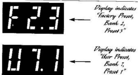
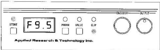
LED Numeric Display
This display tells you whether a preset is factory created (the letter "F" appears in the leftmost position) or user edited (the letter "U"). The mid-
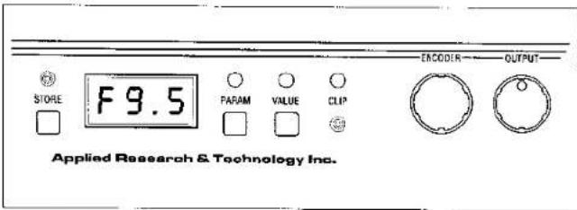
dle and rightmost digits indicate Bank number (0 through 9) and Preset number (0 through 5). The decimal point between the two rightmost positions is used to separate the two numbers.
Param
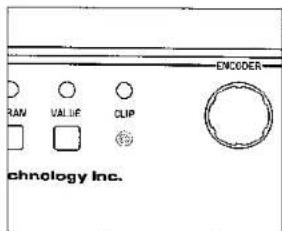
Each Effect and each option in the Misc. and MIDI/Util section has editable parameters, selected by the Param switch and edited via the Value switch and Encoder knob. The Param (Parameter) switch can only be activated when the Mode switch has been pressed and the BCC is in Edit mode. Once the Mode switch has been pressed, pushing the Param button causes the LED above it to illuminate, indicating that the Param function is "live." Simultaneously, the LED below Compress will glow, as will the LED to the right of Param number 1, as shown:


Each time the Encoder knob is turned one click, the next Parameter is selected (2, 3, 4, 5 or 5, 4, 3, 2, etc.). Once the Parameters for the Compressor are cycled through, then the LED below Distort glows, as well as Param number 1's LED, indicating that the next effect, Distortion, is now the Effect whose parameters are being chosen. If you continue turning the Encoder knob, you will cycle through the Parameter numbers for Distortion, then through EQ, etc. The pattern is row-by-row, from left to right.
| COMPRESS | DISTO % | |
| PAHAN | ○ | |
| 1—○ | DRIVE(1-50) | TYPE |
| 2—● | RATIO(1-6) | DRIVE(1-75) |
| 3—● | OUTPUT(1-22) | OUTPUT(1-24) |
| 4—● | ||
| 5—● |
| COMPRESS | DISTORT | |
| PARAM | ○ | ● |
| 1—● | DRIVE(1~15) | TYPE |
| 2—○ | RATIO(4~6) | DRIVE(1~35) |
| 3—● | OUTPUT(1~20) | OUTPUT(1~35) |
| 4—● | ||
| 5—● |
| COMPRESS | DISTORT | |
| PARAM | ○ | ● |
| 1—● | DRIVE(0-19) | TYPE |
| 2—● | RATIO(1-4) | DRIVE(0-23) |
| 3—○ | OUTPUT(1-26) | OUTPUT(0-27) |
| 4—● | ||
| 5—● |
| DIM PRESS | DISTORT | |
| PARAM | ● | ○ |
| 1—○ | DRIVE(0-12) | TYPE |
| 2—● | RATIO(1-4) | DRIVE(0-25) |
| 3—● | OUTPUT(0-20) | OUTPUT(0-25) |
| 4—● | ||
| 5—● |
Note: The number of parameters for each effect varies from 3 to 5; when cycling through these, once the maximum number is reached, then the Param button advances you to the next Effect. Meanwhile, as each Parameter is cycled through, the Numeric Display indicates the current Value of each Parameter.
To move quickly through parameters, follow this procedure:
Once you have selected the Parameter you want to edit, then push the Value button, whose function is explained below. Note that once you have pushed the Value button, you can then push the Value button repeatedly to cycle up through the Parameters. To cycle down through the Parameters, push the Param button repeatedly. You can always use the Encoder knob to speedily move through Parameters or Values, too.


SPECIAL NOTE ON PROGRAMMING THE MODULATION SECTION
When you cycle through the Effects and Parameters, each Effect and Parameter is indicated by continuously glowing LEDs, except when you reach the Modulation Effects section (Flanger, Chorus, Pan/Trem, Pitch Transposer). Then all four of the Effects' LEDs glow together, although the currently active Modulation Effect blinks. (For example, if Flanger is selected, then the LED below Flanger blinks, while the Numeric Display shows the letters "FLA" to indicate that the Flanger is active). To select a different Modulation Effect, press the Value button and turn the Encoder knob until the LED below the name of the Effect you want blinks. Note that the 3-letter name corresponding to the effect will change in the Numeric Display (Fla, cho, uE, or Pit).
Once a new Modulation Effect is selected, then press Param once and turn the Encoder one click to reach the number 1 Parameter for that effect. Note, also, that only the LED corresponding to the selected Modulation Effect glows continuously instead of blinking.
| FLANGER | CHORUS | PAN/TREM | PITCH |
| MODULATION | |||
| ○ | ○ | ○ | ○ |
| TYPE | TYPE | TYPE | TYPE |
| SPEED(1-16) | SPEED(1-16) | SPEED(1-16) | PITCH(-12/+12) |
| WIDTH(1-16) | WIDTH(1-16) | WIDTH(1-16) | FINE(-/+) |
| REGEN(1-16) | INTENSITY(1-10) | LEVEL(1-16) | |
| INTENSITY(1-10) | |||


Value
Once a Parameter has been selected, press the Value button. Its LED glows, indicating that it is "live." Each Parameter has its own Value range, indicated on the front panel. The exception is "Type," which gives you a choice of different types of Distortion, Chorus, etc. See pages 10 through 19 for detailed explanations of the Value ranges and Effects Types.
To change the Value, turn the Encoder knob clockwise or counterclockwise to increase or decrease (respectively) the selected Parameter's value.
Note: After you have changed a Value, you can press Param and cycle to another Parameter (by pressing Param repeatedly—which steps backwards through Parameters—or turning the Encoder knob either way). Press Value again, and you can edit the newly selected Parameter. Pressing Value repeatedly steps up through the Parameters.
Clip LED
The Clip LED tells you if too much signal is reaching the digital processing section of the BCC. If the Clip LED is lit, it indicates overloading, which results in undesirable distortion, also known as clipping. For maximum dynamic range and minimum distortion, the Clip LED should rarely, if ever, flash. If the Clip LED flashes often or continuously, turn down your instrument's output level or adjust the BCC's Input level as outlined in "Setting The Input Level" on page 6.
Encoder
The Encoder knob works in conjunction with the Param, Value, and Store switches to quickly scroll through Parameters, Values, and Preset locations. For specific information on how the Encoder works with these, see the sections on Param (page 23), Value (page 26), and Store (page 22).

Output
The Output control governs the amount of signal leaving the BCC through the Left Out and Right Out jacks. Depending on the type of equipment connected to the unit, and its input needs, it's almost mandatory to experiment in order to find the optimum level. Check your other equipment's manual for hints on setting appropriate input levels. Use your ears as a guide, too.
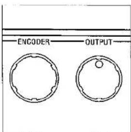
The effect of the BCC's Output knob is global, meaning that it affects the BCC's output level, regardless of what Preset is engaged.
FOOTSWITCHES
The BCC has nine large, rubber footswitches. They are placed far enough apart that you can step on them without inadvertently activating adjacent ones. In addition, the switches are clickless; that is, when you step on them, they don't produce an audible noise. This is ideal for studio and stage settings where "live" microphones are present.
Many of the footswitches are configured to perform dual functions. In normal mode, switches labeled One through Five call up presets 0 through 5 within a bank. In Edit mode, they can be used to add or subtract effects from a chain and to turn individual effects on and off.
Bypass
When you step on the Bypass switch, the LED above it glows continuously to let you know that the input signal is passing straight through to the BCC's output without going through the processing circuitry. The switch is noiseless, so there is no pop or click when you activate or deactivate the Bypass.


Down
The Down button selects the next lowest Bank each time you depress it. The corresponding Bank number (0 through 9) shows in the display's middle digit. In Play mode, the Down button selects the next lowest Bank each time you depress it. The corresponding bank number shows in the middle digit. The Preset change is immediate.
If the BCC is in Edit mode, when you push the Down button, the next lowest Preset in the current Bank is selected.
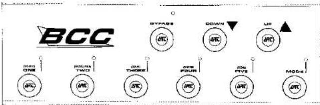
Up
The Up button selects the next highest Bank each time you depress it. The corresponding Bank number (0 through 9) shows in the display's middle digit. In Play, mode the Up button selects the next highest Bank each time you depress it. The corresponding bank number shows in the middle digit. The Preset change is immediate.
If the BCC is in Edit mode, when you push the Up button, the next highest Preset in the current Bank is selected.
Numbered Footswitches
Each of the numbered footswitches has a dual function. In Play mode, the numerical value (one, two, three, four, five) is active, and each time you step on one of the switches, the corresponding Preset number is recalled.


When you step on the Mode switch, placing the BCC in Edit mode, then the switches function as individual on/off switches for the effects shown in parenthesis (Distort, Modulation, Delay, Reverb, Pedal). When the BCC is in Edit mode and you step on one of the footswitches, the corresponding effect is bypassed, and the LED above the switch blinks. The next time you step on that switch, the effect is again active, and the LED glows continuously.
Note: Because some Presets are set up with some effects bypassed, when you step on the Mode switch to enter Edit mode, any bypassed effects are immediately indicated by their corresponding LEDs flashing.
Here are the numbered footswitches and their respective Edit mode functions shown in parenthesis:
One (Distort)
Two (Modulation)
Three (Delay)
Four (Reverb)
Five (Pedal)
Mode
When this switch is pressed, the BCC is placed in Edit mode, which means that you can individually turn Effects on and off, edit Parameters, and store Presets.
After the Mode switch is pressed, the LED next to each numbered footswitch either glows continuously, showing it effect is engaged, or flashes on and off, meaning that the effect is bypassed. In addition, only in Edit mode can you edit or store Presets.
With the BCC in Edit mode, you can press the Param button to edit Parameters. When you press the Param button, an LED in the indicator


matrix' far left vertical column glows, as does one in the top row of the matrix. By reading from top to bottom and left to right, you know which Parameter is selected for editing. To change the selection, you can turn the Encoder knob clockwise or counterclockwise to scroll through the Parameters. Once you select the Parameter you want to edit, press Value and turn the Encoder to the appropriate setting. You can scroll backwards through the parameters by pressing the Parameter button repeatedly; each press of the button progresses backwards one step.
To store your changes, press Store once. The Numeric Display will blink, and you can either save the edited Preset where it currently is—by pressing Store again—or select another location by turning the Encoder until you scroll to the Bank and Preset location you desire. Then press Store to save it there. (The Numeric Display will stop blinking and glow steadily.)
To exit Edit mode, simply step on the Mode switch. The LED above Mode, as well as the LEDs above the numbered footswitches will be extinguished.
REAR PANEL
Always use good-quality shielded cables for connections to the Input, Loop Send and Loop Return, Pedal, and Left and Right Out.
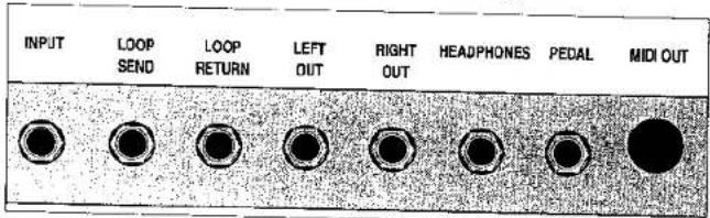
Input
The Input jack accepts a 1/4" mono plug—the kind found on guitar cords. The high input impedance acts as a buffer that keeps the bass' signal from being loaded down, thereby assuring the highest fidelity signal reaching the BCC's internal effects.


Loop Send
The Loop Send is a 1/4" jack that sends the Analog Effects' output to external processors. It can also be used as a pre-Digital Effects output to another amp, recording gear, tuner, etc.
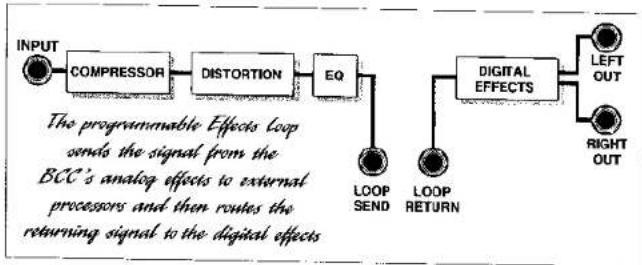
flowchart
graph LR
    A["INPUT"] --> B["COMPRESSOR"]
    B --> C["DISTORTION"]
    C --> D["EQ"]
    D --> E["LOOP SEND"]
    D --> F["LOOP RETURN"]
    D --> G["DIGITAL EFFECTS"]
    G --> H["LEFT OUT"]
    G --> I["RIGHT OUT"]
    style A fill:#f9f,stroke:#333
    style B fill:#ccf,stroke:#333
    style C fill:#cfc,stroke:#333
    style D fill:#fcc,stroke:#333
    style E fill:#cff,stroke:#333
    style F fill:#ffc,stroke:#333
    style G fill:#fcf,stroke:#333
    style H fill:#cff,stroke:#333
    style I fill:#ffc,stroke:#333
Loop Return
The Loop Return is a 1/4" jack that accepts the output from external processors and sends it to the BCC's Modulation Effects and other Digital Effects only when the Loop is enabled in the current Preset.
Left Out
This low-impedance 1/4" output carries the final signal from the BCC after all processing has been performed by the BCC's effects. If you are employing the BCC in a mono setup requiring only one output, use this output.
Right Out
This low-impedance 1/4" output carries the final signal from the BCC after all processing has been performed by the BCC's effects. You can use this to send a signal to a second amp, to a mixing console, etc., for stereo applications
Headphones
This 1/4" output jack is for driving a set of headphones—perfect for auditioning your Presets or practicing without disturbing others. The Output level control on the BCC's front panel governs the output level.


Caution: The Headphones output can provide an extremely loud signal to your headphones. Make sure the Output control is turned to a low setting before you put them on—then bring up the volume to a comfortable level.
Pedal
This 1/4" input jack is for connecting a pedal such as ART's AP-1 Power Pedal or other potentiometer-type pedals to control volume or wah-wah effects in the BCC (don't use an active pedal or one that relies on a photoelectric sensor; it won't work with the BCC). You can use either a shielded or unshielded cable for connecting a pedal to this input. See page 17 for details on programming the Pedal input.
Note: The BCC prefers to be driven by a pedal containing a 100k ohm audio (log-taper) potentiometer. To accommodate a wide variety of pedals using pots of different values, the BCC automatically adjusts its range to match the pedal in use. When the Pedal function is enabled, just rock the pedal through its full range once. The BCC does the rest.
MIDI Out
The BCC is designed to send MIDI Program Change commands to other MIDI gear via the MIDI Out jack. This is useful if you connect the BCC to a multi-channel amp or other signal processors that offer MIDI control. Preset 0.1 sends MIDI Program Change message number 0; preset 0.2 sends Program Change 1, etc., up to preset 9.5 sending Program Change message 49. See MIDI/Util, page 18 for details on setting the appropriate MIDI channel.
Power
This input is designed to accept a 9-volt AC input from the adapter supplied by ART with your BCC.

SETUP DIAGRAMS
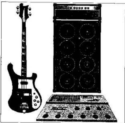
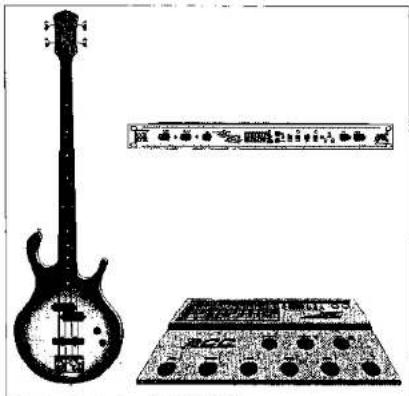
PLUGGING DIRECTLY INTO A BCC & AMP
natural_image
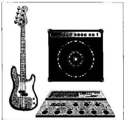
Illustration of a electric guitar, amplifier, and audio equipment (no text or symbols)When plugging a bass into the BCC, make sure that there is sufficient signal level coming from the instrument. Pay attention to the Clip LED on the BCC's front panel, and set the Input level and the instrument's volume control to get the best level and signal-to-noise ratio.
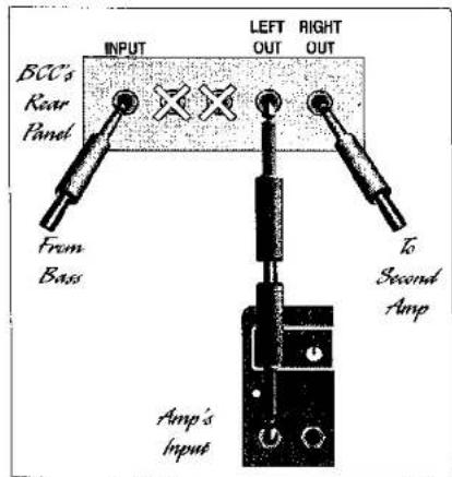

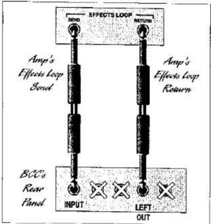
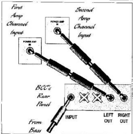
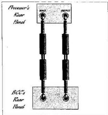
USING THE BCC IN AN AMP'S EFFECTS LOOP
natural_image
Black-and-white illustration of a electric guitar, a speaker chamber, and an electronic device (no text or symbols visible)Patch the BCC into the effects loop of an instrument amplifier as shown below (for mono setups, use the BCC's Left Out jack). If the amp has two effects-loop return jacks for stereo operation, you may connect a second cord between the BCC's Right Out and the amp's second return jack.
flowchart
graph TD
    A["Input"] --> B["BCCs Rear Panel"]
    B --> C["Turnout"]
    C --> D["Turnout"]
    D --> E["Turnout"]
    E --> F["Turnout"]
    F --> G["Turnout"]
    G --> H["Turnout"]
    H --> I["Turnout"]
    I --> J["Turnout"]
    J --> K["Turnout"]
    K --> L["Turnout"]
    L --> M["Turnout"]
    M --> N["Turnout"]
    N --> O["Turnout"]
    O --> P["Turnout"]
    P --> Q["Turnout"]
    Q --> R["Turnout"]
    R --> S["Turnout"]
    S --> T["Turnout"]
    T --> U["Turnout"]
    U --> V["Turnout"]
    V --> W["Turnout"]
    W --> X["Turnout"]
    X --> Y["Turnout"]
    Y --> Z["Turnout"]
    Z --> A
    style A fill:#f9f,stroke:#333
    style B fill:#ccf,stroke:#333
    style C fill:#cfc,stroke:#333
    style D fill:#fcc,stroke:#333
    style E fill:#cff,stroke:#333
    style F fill:#ffc,stroke:#333
    style G fill:#fcc,stroke:#333
    style H fill:#ffc,stroke:#333
    style I fill:#fcc,stroke:#333
    style J fill:#ffc,stroke:#333
    style K fill:#fcc,stroke:#333
    style L fill:#ffc,stroke:#333
    style M fill:#fcc,stroke:#333
    style N fill:#ffc,stroke:#333
    style O fill:#fcc,stroke:#333
    style P fill:#ffc,stroke:#333
    style Q fill:#fcc,stroke:#333
    style R fill:#ffc,stroke:#333
    style S fill:#fcc,stroke:#333
    style T fill:#ffc,stroke:#333
    style U fill:#fcc,stroke:#333
    style V fill:#ffc,stroke:#333


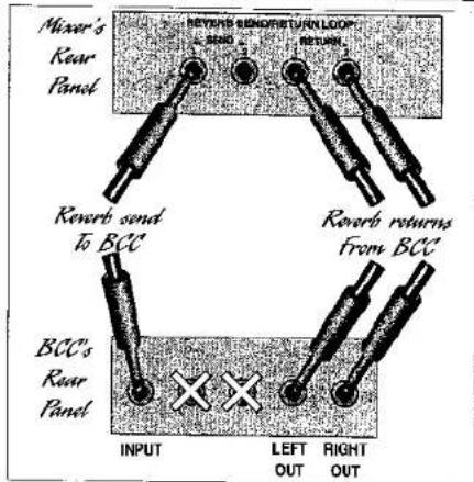
PATCHING THE BCC INTO A MIXER'S REVERB SEND/RETURN LOOP
natural_image
Illustration of a electric guitar, an analog keyboard, and a grid-patterned device (no text or symbols)To connect the BCC into the reverb send/return loop of a mixer, follow the diagram below. If the mixer has only one input and one output(mono), connect them to the BCC's Input and Left Out only. If the mixer has two reverb return jacks for stereo operation, you may connect a second cord between the BCC's Right Out and the mixer's second return jack.
flowchart
graph TD
    A["Mixer's Rear Panel"] --> B["Reverb send to BCC"]
    B --> C["INPUT"]
    C --> D["LEFT OUT"]
    D --> E["RIGHT OUT"]
    F["Reverb returns from BCC"] --> C
    G["REVERB SENSOR RETURN LOOP"] --> C
    H["RETURN"] --> C
    I["BCC's Rear Panel"] --> C
    style A fill:#f9f,stroke:#333
    style F fill:#f9f,stroke:#333
    style G fill:#f9f,stroke:#333
    style H fill:#f9f,stroke:#333
    style I fill:#f9f,stroke:#333


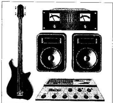
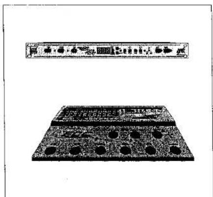
USING THE BCC IN STEREO WITH A POWER AMP & SPEAKERS
natural_image
Black-and-white photo of an electric guitar, two analog speakers, and a control panel (no visible text or symbols)Patch the Right Out and Left Out from the BCC into the power amp's inputs or into the power-amp inputs on two instrument amplifiers. You can also plug directly into the amps' front-panel inputs, but you will need to adjust the BCC's output level and the amps' gain controls accordingly.


PATCHING ANOTHER SIGNAL PROCESSOR INTO THE BCC'S EFFECTS LOOP
natural_image
Illustration of an electric guitar and a portable electronic device (no text or symbols visible)Connect the BCC's Loop Send to the input of an external signal processor, and from the processor's output to the BCC's Loop Return, using shielded cables. Set the processor's input and output levels for minimum distortion but a high enough level to minimize hiss and noise.


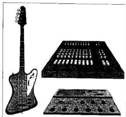
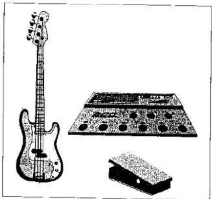
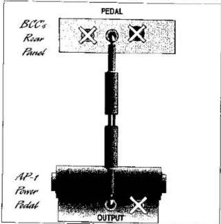
USING AN EXTERNAL PEDAL TO CONTROL BCC WAH-WAH AND VOLUME FUNCTIONS
natural_image
Illustration of a electric guitar, an electronic audio amplifier, and a small electronic device (no text or symbols present)Using either a shielded or unshielded cable with 1/4" plugs, connect a potentiometer-style volume pedal such as ART's AP-1 Power Pedal to the BCC's Pedal input. (If you use the AP-1 pedal, connect its Output jack to the BCC's Pedal input. Other pedals may require using the input or output, depending on their configuration.) Program the BCC Presets of your choice for Volume or Wah-Wah function.

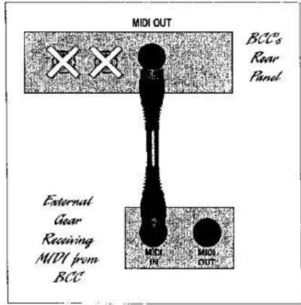
USING THE BCC'S MIDI OUT TO CONTROL OTHER GEAR
natural_image
Two rectangular electronic components with circular holes and a horizontal bar above (no visible text or symbols)Use a shielded MIDI cable to connect the MIDI Out from the BCC to the MIDI In of a signal processor, sampler, etc. Make sure that the BCC and the other piece of equipment are operating on the same MIDI Channel. The BCC sends MIDI Program Change commands, allowing you to change presets on remote gear each time you change presets on the BCC.


WARRANTY & SERVICE INFORMATION
LIMITED WARRANTY
Warranty service for this unit will be provided by Applied Research & Technology, Inc. in accordance with the following warrant statement.
Applied Research & Technology, Inc. (ART) warrants to the original purchaser that this product and the components thereof will be free from defects in workmanship and materials for a period of one year from the date of purchase. Applied Research & Technology, Inc. will, without charge, repair or replace, at its option, defective product or component parts upon prepaid delivery to the factory service department or authorized service center, accompanied by proof of purchase date in the form of a valid sales receipt.
EXCLUSIONS: This warranty does not apply in the event of misuse or abuse of the product or as a result of unauthorized alterations or repairs. This warranty is void if the serial number is altered, defaced, or removed.
ART reserves the right to make changes in design or make additions to or improvements upon this product without any obligation to install the same on products previously manufactured.
ART shall not be liable for any consequential damages, including without limitation damages resulting from loss of use. Some states do not allow limitation of incidental or consequential damages, so the above limitation or exclusion may not apply to you. This warranty gives you specific rights and you may also have other rights which vary from state to state.
For units purchased outside the United States, service will be provided by an authorized distributor of Applied Research & Technology, Inc.

Service
The following information is provided in the unlikely event that your unit requires service. Use this procedure to return units in the United States only. For service outside of the U.S., please contact your authorized ART distributor
1) Be sure that the unit is the cause of the problem. Check to make sure the unit has power supplied, all cables are connected correctly, and the cables themselves are in working condition.
2) If you find the unit to be at fault, write down a description of the problem, including how and when the problem occurs.
3) Call the factory for a Return Authorization (RA) number.
4) Pack the unit in its original carton or a reasonable substitute. The packing box is not recommended for a shipping carton. Put the packaged unit in another box for shipping. Print the RA number clearly under the address.
5) Include with your unit: a return shipping address (we cannot ship to a P.O. Box), a copy of your purchase receipt, a daytime phone number, and a description of the problem.
6) Ship only your unit and its power supply (keep your manual!) to: APPLIED RESEARCH & TECHNOLOGY, INC. 215 TREMONT STREET ROCHESTER, NY 14608 ATTN: REPAIR DEPARTMENT RA # ____
7) Contact our customer service department at (716) 436-2720 for your Return Authorization number or questions regarding repairs. Customer Service hours are 8:30 AM to 5:00 PM Eastern Time, Monday through Friday.
Customer Service
You may contact ART's Customer Service Department between the hours of 8:30 AM and 5:00 PM Eastern Time Monday through Friday. The Customer Service Department will answer technical questions about ART products and provide information concerning service.


BCC Presets
Bank 0
F0.1 Jeremy
F0.2 Spoonman
F0.3 Heavy Dirge
F0.4 Jaco Solo
F0.5 Cool Flange
Bank 1
F1.1 Charlie Brown
F1.2 Mud Funk
F1.3 Floating Bass
F1.4 Drainpipe
F1.5 Bass Oddity
Bank 2
F3.1 Bootsy Funk
F3.2 Bass Solo Double
F3.3 Heavy Distortion
F3.4 DTW Bass
F3.5 You're No Good-VH II
Bank 3
F3.1 3rd Bass From the Sun
F3.2 Bass Return
F3.3 Bass Invaders
F3.4 Time Bass
F3.5 Precious Dream
Bank 4
F4.1 Harmonic Display
F4.2 Fretless Wonder
F4.3 Tap Dancer
F4.4 Sea Bass
F4.5 Difficult 2 Cure


Bank 5
F5.1 Synth Bass 3
F5.2 Flanged Bass
F5.3 Nose Of Funk
F5.4 Big Bottom
F5.5 .5 Sec. Delay
Bank 6
F6.1 No Frills
F6.2 Dirt
F6.3 Grind Vol. 1
F6.4 Super Trip Delay
F6.5 Xanadu
Bank 7
F7.1 Super Chorus
F7.2 Grind Vol. 2
F7.3 Super Twang
F7.4 Chorus Grind
F7.5 Fender Jazz
Bank 8
F8.1 Born in Chicago
F8.2 Finger Style Jazz
F8.3 Rockabilly Slap
F8.4 Fretafifth
F8.5 Mr. Petterrsson
Bank 9
F9.1 Solo Fretless
F9.2 SVT in a Box
F9.3 Sub-Rave
F9.4 Deep Dub
F9.5 Dan Electro