S5 - 120 Bogen - Panduan pengguna gratis
Temukan panduan perangkat secara gratis S5 Bogen dalam format PDF.

Pertanyaan pengguna tentang S5 Bogen
0 pertanyaan tentang perangkat ini. Jawab yang Anda tahu atau ajukan milik Anda sendiri.
Ajukan pertanyaan baru tentang perangkat ini
Unduh instruksi untuk 120 dalam format PDF gratis! Temukan panduan Anda S5 - Bogen dan ambil kembali perangkat elektronik Anda. Di halaman ini diterbitkan semua dokumen yang diperlukan untuk penggunaan perangkat Anda. S5 merek Bogen.
PANDUAN PENGGUNA S5 Bogen

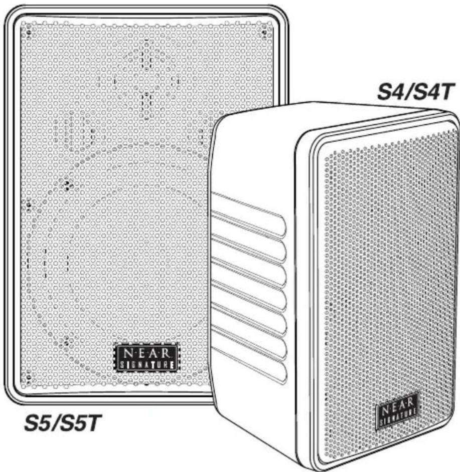
Owner's Guide:
Models S5/S5T and S4/S4T
Installation Instruction Manual
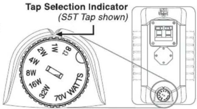
Power Tap Selection
S5T - 8-ohm or 70V - 32W/16W/8W/4W/2W/1W S4T - 8-ohm or 70V - 16W/8W/4W/2W/1W
IMPORTANT: When connecting to a 70V amplifier, make sure that the Tap Selector is not in the "8Ω" position.
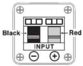
Speaker Connections and Polarity
Strip about 1/2" of insulation from the wires. Push down on the spring clamps, and insert the wire into the hole, then release the clamp. To ensure proper polarity, wire black terminals to black terminals and red terminals to red terminals on the same speaker run.
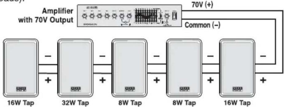
70V System Configurations
When designing a 70V system, the total of all power tap settings of all the connected speakers CANNOT EXCEED the output power of the 70V amplifier (amplifier power can exceed the sum of the speaker loads).
flowchart
graph LR
    A["16W Tap"] -->|+| B["32W Tap"]
    B -->|+| C["8W Tap"]
    C -->|+| D["8W Tap"]
    D -->|+| E["16W Tap"]
    F["Amplifier with 70V Output"] --> G["70V (+)"]
    F --> H["Common (-)"]
EXAMPLE: 16 + 32 + 8 + 8 + 16 = 80 Watts minimum amplifier output power rating.
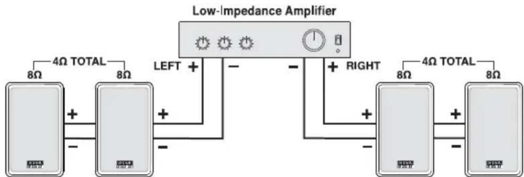
Low-Impedance System Configurations
When wiring together multiple NEAR Signature speakers set to 8 ohms, it is important to calculate (using Ohm's Law) the total load that these speakers present to the amplifier. The total load impedance of the interconnected speakers cannot be lower than the minimum load impedance rating of the low-impedance amplifier. Also care must be taken to ensure the amplifier cannot overdrive the speaker's max power rating.
flowchart
graph LR
    A["Low-Impedance Amplifier"] -->|4Ω TOTAL| B["Device 1: 8Ω"]
    A -->|LEFT +| C["Device 2: +"]
    A -->|RIGHT +| D["Device 3: +"]
    B -->|+| E["Device 4: +"]
    C -->|-| E
    D -->|-| E
    style A fill:#f9f,stroke:#333
    style B fill:#ccf,stroke:#333
    style C fill:#cfc,stroke:#333
    style D fill:#fcc,stroke:#333
EXAMPLE: Two 8Ω speakers in parallel = 4Ω. The amplifier must be rated to work into 4Ω loads. Also in this example, the max amplifier output power rating (each channel into 4Ω) should not exceed 150W for S4/T (2 X 75W) speakers or 300 for S5/T (2 X 150W).
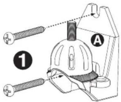
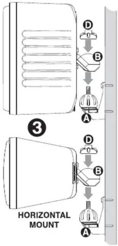
Wall-Mounting Instructions
- Secure Mounting Base (A) to wall as shown.
IMPORTANT: THE WALL MATERIAL AND USER SUPPLIED ATTACHMENT HARDWARE MUST BE ABLE TO RESIST A PULL OUT FORCE OF AT LEAST 10X THE WEIGHT OF THE SPEAKER.
- Determine the desired orientation (horizontal or vertical) for the speaker. Attach the Mounting Cup Bracket (B) to the indentation (C) on the back of the speaker enclosure using the two supplied M5 screws as shown.
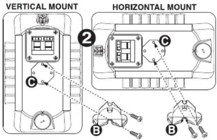
- Connect the speaker wires to the rear input terminals on the loudspeaker. Set the speaker with Mounting Cup Bracket (B) over the Mounting Base (A). Loosely screw the Mounting Cap Nut (D) onto the Mounting Base threaded stud.
Aim the speaker and then firmly tighten the Mounting Cap Nut (D) with a 1/2" nut driver or socket wrench. Be careful not to over-tighten.
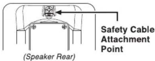
Safety Cable Attachment Point
The NEAR Signature speakers provide an attachment point for a user-supplied safety cable. The other end of the safety cable must be attached to a user-supplied anchor independent of the speaker mounting hardware. All hardware, including the cable, must be rated to withstand a force 10X greater than the weight of the speaker.
Care & Maintenance
If needed, you may clean the speaker cabinet by using only soap and water with a soft cloth to wipe gently.
VERTICAL MOUNT
Technical Specifications
| S4/S4T | S5/S5T | |
| Frequency Response (-10 dB)*: | 58 Hz to 18 kHz | 48 Hz to 17 kHz |
| Low Frequency Design – Metal-Composite Cone Utilizing MLS Voice Coil Guidance System: | 4-1/2" Nominal Dia. | 5-1/4" Nominal Dia. |
| High Frequency Driver – Titanium Cone: | 1" Nominal Dia. | 1" Horn-Loaded |
| Sensitivity (1W/1m, Ave. 100 Hz to 15 kHz): | 86 dB SPL | 89 dB SPL |
| Dispersion Horizontal: Vertical: | 150 Degrees 120 Degrees | 130 Degrees 110 Degrees |
| Impedance Ratings Low: High: | 8Ω Only (S4 version) 70V and 8Ω (S4T version) | 8Ω Only (S5 version) 70V and 8Ω (S5T version) |
| Power Input (Maximum): | 75W @ 8 ohms | 150W @ 8 ohms |
| Power Taps 70V: | 16, 8, 4, 2, 1 watts | 32, 16, 8, 4, 2, 1 watts |
| Product Weight: | S4: 5 lbs./S4T: 6 lbs. | S5: 8 lbs./S5T: 9 lbs. |
| Speaker Dimensions (WxHxD) Without Bracket: With Bracket: | 5-1/4" x 8-1/4" x 5-3/8" 5-1/4" x 8-1/4" x 7-3/8" | 6-7/8" x 9-3/4" x 6-1/8" 6-7/8" x 9-3/4" x 8-1/8" |
| Enclosure Material: | High-Impact ABS | |
| Product Color: | White ("W" suffix) and Black ("B" suffix) | |
| Mounting Bracket Material: | Aluminum Alloy, Powder-Coated Finish | |
| Grille Material: | Perforated Aluminum, Powder-Coated Finish | |
| Terminations: | Pressure Clamp | |
| Included Accessories: | Color-Matched Mounting Bracket | |
| Optional Accessories: | Safety Cable CK10 | |
* Half-Space Response
Limited Warranty; Exclusion of Certain Damages
NEAR® Signature models are warranted to be free from defects in material or workmanship for five (5) years from the date of sale to the original purchaser. Any part of the product covered by this warranty that, with normal installation and use, becomes defective will be repaired or replaced by Bogen, at our option, provided the product is shipped insured and prepaid to: Bogen Factory Service Department, 50 Spring Street, Ramsey, NJ 07446, USA. The product will be returned to you freight prepaid. This warranty does not extend to any of our products that have been subjected to abuse, misuse, improper storage, neglect, accident, improper installation or have been modified or repaired or altered in any manner whatsoever, or where the serial number or date code has been removed or defaced.
THE FOREGOING LIMITED WARRANTY IS BOGEN'S SOLE AND EXCLUSIVE WARRANTY AND THE PURCHASER'S SOLE AND EXCLUSIVE REMEDY. BOGEN MAKES NO OTHER WARRANTIES OF ANY KIND, EITHER EXPRESS OR IMPLIED, AND ALL IMPLIED WARRANTIES OF MERCHANTABILITY OR FITNESS FOR A PARTICULAR PURPOSE ARE HEREBY DISCLAIMED AND EXCLUDED TO THE MAXIMUM EXTENT ALLOWABLE BY LAW. Bogen's liability arising out of the manufacture, sale or supplying of products or their use or disposition, whether based upon warranty, contract, tort or otherwise, shall be limited to the price of the product. In no event shall Bogen be liable for special, incidental or consequential damages (including, but not limited to, loss of profits, loss of data or loss of use damages) arising out of the manufacture, sale or supplying of products, even if Bogen has been advised of the possibility of such damages or losses. Some States do not allow the exclusion or limitation of incidental or consequential damages, so the above limitation or exclusion may not apply to you. This warranty gives you specific legal rights, and you may also have other rights which vary from State to State.
Products that are out of warranty will also be repaired by the Bogen Factory Service Department -- same address as above or call 201-934-8500. The parts and labor involved in these repairs are warranted for 90 days when repaired by the Bogen Factory Service Department. All shipping charges in addition to parts and labor charges will be at the owner's expense. All returns require a Return Authorization number.
7/22/2008