50PD960DTA - Televízió HITACHI - Ingyenes használati útmutató
Találja meg az eszköz kézikönyvét ingyenesen 50PD960DTA HITACHI PDF formátumban.

Felhasználói kérdések a következőről 50PD960DTA HITACHI
0 kérdés erről a készülékről. Válaszolj azokra, amiket ismersz, vagy tedd fel a sajátod.
Tegyél fel egy új kérdést erről a készülékről
Töltse le az útmutatót a következőhöz Televízió PDF formátumban ingyenesen! Találja meg kézikönyvét 50PD960DTA - HITACHI és vegye vissza elektronikus eszközét a kezébe. Ezen az oldalon közzé van téve az eszköze használatához szükséges összes dokumentum. 50PD960DTA márka HITACHI.
HASZNÁLATI ÚTMUTATÓ 50PD960DTA HITACHI
USER MANUAL 50PD960DTA
Thank you for purchasing the Hitachi Plasma Television. Please read this user manual carefully before operating this product.
To ensure proper operation, please read and follow ALL the instructions, especially the "IMPORTANT SAFETY INSTRUCTIONS" and "SAFETY PRECAUTIONS".
Please keep this user manual for future reference.
CONTENTS
IMPORTANT SAFETY INSTRUCTIONS ..... 1
INTRODUCTION 2
About This Manual 2
Trademark Credits 2
About Software 2
SAFETY PRECAUTIONS 3
About the Symbols 3
Cleaning and Maintenance 6
ABOUT PLASMA DISPLAY PANEL 7
Image Retention of Plasma Display 7
Common Characteristics of
Plasma Display Panels 7
FEATURES 8
SUPPLIED ACCESSORIES 8
OPTION 8
COMPONENT NAMES 9
Main Unit 9
Remote Control 10
PREPARATION ....11
Remote Control Batteries Installation 11
Handling the Remote Control 11
Caution When Moving the Main Unit 11
Safety Precaution on Main Unit Installation ..... 12
Anti-Tumble Measures 12
CONNECTION 13
Terminal Positions 13
Connecting Procedure 13
BASIC OPERATION 18
Power On/Off 18
First Time Setup 19
Volume UP/DOWN 19
Mute 19
Input Switching to DTT/TV, AV1\~4, HDMI,
and RGB 20
Input Signal Screen Display 20
TV SETUP OPERATION 21
How to use the On-Screen Display
(OSD) system 21
Setup Menu (TV mode) 22
Setup Menu (AV mode) 24
Setup Menu (RGB mode) 25
Function Menu 26
Picture Menu (TV/AV mode) 28
Picture Menu (RGB mode) 31
Audio Menu 33
Timer Menu 34
Analog Teletext 35
DIGITAL TERRESTRIAL TELEVISION (DTT)
OPERATION 36
How to use the On-Screen Display
(OSD) system 36
DTT Main Menu List 36
Installing Channels 37
Restoring Channels 37
Channel Selections 38
Making Favorite List 39
Utilizing the Information Tool 40
Configuring Setting 42
Checking DTT System Information 43
TV Setup Menu 43
FUNCTION 44
Size Switching 44
Picture Freezing 47
Audio Switching 48
Power Save Mode 49
DVD Player / STB Selection 50
TROUBLESHOOTING ....51
When Following Messages Appear
on the Screen 51
Symptom and Check List 51
PRODUCT SPECIFICATIONS 54
Signal Input 55
Recommended Signal List 56
IMPORTANT SAFETY INSTRUCTIONS
- Read this instruction thoroughly.
- Retain this instruction for future reference.
- Heed all warnings and cautions to prevent possible danger.
- Follow all instructions. Improper handling could cause personal injury and/or serious damage to the unit that may shorten its service time.
- Do not block any ventilation openings.
- Install the product in accordance with the manufacture's instructions.
- Before calling for the technical support or service technician, read "TROUBLESHOOTING" (51 \~ 53) to determine the symptoms when problems occur during installation or operation of the product.
- If serious problems happen (such as smoke or an abnormal odor from the unit), turn off the Main Power, unplug the Power Cord, and then, contact your local dealer immediately.
INTRODUCTION
Thank you for purchasing the Hitachi Plasma Television. We hope that you will enjoy the great performance with this product.
This Plasma television has been designed to meet the international standards. However, it could cause personal injuries and property damage if improperly handled. In order to prevent potential danger and obtain maximum benefit from your set, please observe the following instructions when installing, operating, and cleaning the product.
Keep this manual for future reference, and record the serial number of your set in the space provided on the front cover page of this manual.
About This Manual
• The information in this manual is subject to change without notice.
- This manual has been created with extra care. In case that you have any comments or questions regarding this manual, please contact your local dealer or our Customer Service Center.
- Before operating this set, please fully understand the prerequisite such as specifications or constraints of the hardware and software. We are not responsible and have no liability for any loss, damage or injury as a result of misuse.
- Reproduction, copying, use, modification, and/or transmission in whole or in part of this manual are prohibited without any prior written permission.
- All other products and company names used in this manual are trademarks or registered trademarks of their respective owners.
Trademark Credits
• VGA and XGA are trademarks of International Business Machines Corporation.
• VESA is a registered trademark of the Video Electronics Standard Association.
- Licensed by BBE Sound, Inc. under USP5510752 and 5736897. BBE and BBE symbol are registered trademarks of BBE Sound, Inc. Manufactured under license from BBE Sound, Inc.
- WOW, SRS and (●) symbol are trademarks of SRS Labs, Inc.
WOW technology is incorporated under license from SRS Labs, Inc.
- HDMI, the HDMI logo and High-Definition Multimedia Interface are trademarks or registered trademarks of HDMI Licensing LLC.
• DVB is a registered trademark of the DVB Project.
Even if no special notation has been made of company or product trademarks, these trademarks have been fully respected.
About Software
You may not alter, decompile, disassemble, decrypt, or otherwise reverse-engineer the Software installed in this product, which are prohibited by law.
SAFETY PRECAUTIONS
For your safety, please read the following precautions carefully before using this product. Improper use would cause serious personal injuries and/or damage to your property or this product.
About the Symbols
The following are the symbols used in this manual and affixed on the unit itself. Please fully understand the meanings of the symbols before reading the instructions in this section.
 | Never ignore the instruction. There are risks of serious injuries or possible death to the user. |
 | Do not ignore the instruction. There are possibilities of personal injuries and/or property damage. |
| Other Symbols | |
 | The triangle with illustration is intended to alert the users that there are possibilities of fire, explosion, or high temperatures if the product is handled improperly.Each illustration within the triangle specifies the contents in detail. (The figure on the left is an example.) |
 | The circle with diagonal line and illustration indicates a prohibited action (the symbol to the left indicates that disassembly is prohibited). |
 | This symbol indicates a compulsory action.The contents will be clearly indicated in an illustration or nearby (the symbol to the left indicates that the power plug should be disconnected from the power outlet). |
WARNING
| WARNING | |
| There is a risk of fire, electric shock, or serious injury. | |
| ■ Unplug the power cord immediately when serious problems occur.Serious problems such asSmoke, abnormal odor or noise comes out from the product.No picture, no sound or distorted picture on the display.Foreign objects (such as water, metals etc.) get inside the unit.Do not continue using the product under these abnormal conditions.Turn off the Main Power, unplug the Power Cord, and contact your dealer immediately.For your safety, never try to repair the product by yourself. |  Disconnect the plug from the power outlet. Disconnect the plug from the power outlet. |
| ■ Do not insert liquids or any foreign objects (such as metals or flammable items) inside the unit.In case it happens, turn off the main power, unplug the Power Cord, and contact your dealer immediately.Use special caution when younger children are around the unit. |  |
| ■ Do not remove cover, or modify the product.High-voltage components are installed inside of the unit. Removing covers can expose you to high voltage, electrical shock, and other dangerous conditions.Contact your local dealer to perform servicing such as inspection, adjustment, or repair work. |   Do not disassemble Do not disassemble |
Disconnect the plug from the power outlet.
SAFETY PRECAUTIONS (continued)
 | |
| There is a risk of fire, electric shock, or serious injury. | |
| Install the unit at a proper area where it does not expose anyone to any danger.If you hit against the edge of the unit, you may be injured. |  |
| Do not place any objects on top of the unit.Objects such asLiquid containers (vase, fish tank, flowerpot, cosmetics or liquid medicine).If water or any liquid spill onto the unit, it may cause short-circuit and result in fire or electrical shock.In case that it happens, turn off the Main Power, unplug the Power Cord, and contact your dealer immediately.Do not place anything heavy on top of the unit.Do not climb on or hang from the unit.Do not let your pets get on top of the unit |  |
| Do not expose this unit to rain or moisture.Never use this unit in the bathroom or shower room.Beware when you use this product outside, especially in rainy, or snowy weather, and at the beach or waterfront.When the product gets wet, it could cause fire or electrical shock. |   |
| Unplug this unit during lightning storm.To reduce the risk of electrical shock, do not touch the product when starts lightning. |   Disconnect the plug from the power outlet. Disconnect the plug from the power outlet. |
| Do not do anything that may damage the Power Cord.Do not damage, modify, twist, forcibly bend, heat, or pull excessively the Power Cord.Do not place heavy objects (including the unit itself) on top of the Power Cord.If the Power Cord is damaged, contact your dealer for repairs or exchange. |  |
| Use only with designated power supply voltage.To prevent the risk of fire and electrical shock, operate this product only with the power supply voltage indicated on the unit. |  |
| Beware not to drop or have any impact on the unit.Take extra care while moving the unit.The plasma display panel is made of glass. In case that it breaks, you may be injured by the broken pieces.In case that you drop the unit or the cabinet is damaged, turn off the Main Power, unplug the Power Cord and contact your local dealer immediately.Continuing use of the product with above conditions may cause fire or electrical shock. |  |
| Clean dust or metals on or around the blade of the power plug regularly.Continuing use of the product with above condition may cause fire or electrical shock.Always unplug the Power Cord first, and clean the blades with a dry cloth. |  |
| Do not place the unit on an unstable surface.Unstable places such asTilted surface or shaky rack, table, stand or trolley.If the unit falls down, it could cause personal injury. |  |
| Do not place your fingers into the gap at the opened front door of the unit.If your fingers are caught in the front door, you may be injured.Do not allow children to touch the front door or play near it. |  |
SAFETY PRECAUTIONS (continued)
| CAUTION | |
| ■ Do not place the unit at a dusty place.It could cause malfunction. |  |
| ■ Do not cover or block any ventilation holes on the product.The unit would overheat, and it could cause fire or damage the product which may shorten its service life.· Install the product in accordance with the instructions in this manual.· Do not place the unit with ventilation side down.· Do not install the unit on the carpet or bedclothes.· Do not cover the unit with table cloth etc. |  |
| ■ Be sure to ground the earth cable correctly.· Especially when you use Power Cord adapter, be sure to connect the earth cable to the ground terminal. Incorrect connection would cause fire or electrical shock.· For your safety, always make sure to unplug the Power Cord before connect or disconnect the earth cable . |  Supply connect the ground wire. Supply connect the ground wire. |
| ■ Follow the Anti-tumble measures in this manual.· If the unit tumbles over, there is a risk of personal injury and possible death. Also, it would damage the product seriously. |  |
| ■ Do not install the unit near the medical devices.· To prevent malfunction of the medical devices, do not use this product and medical devices in the same room. |  |
| ■ Do not place a CRT-based television near the speakers of the Plasma Television.· It could cause the partial discoloration or blurring of the image on the CRT-based television.Please install it away from the speakers of the unit. |  |
| ■ Disconnect all of the external connection cables and detach the anti-tumble measures before moving the unit.· It may cause fire, electrical shock, or personal injuries. |  |
| ■ Connect the power plug securely.· Improper connection will cause overheating and may result in fire.· Do not touch the blades of the plug while connecting it to the wall socket. It could cause electrical shock.· If the plug is not fitted for the wall socket, contact your dealer for replacement. |  |
| ■ Do not handle the Power Cord with wet hands.· It could result in electrical shock. |  |
| ■ Do not pull the cord when you unplug the Power Cord.· It may damage the cord and could result in fire or electrical shock.· Hold the plug when disconnecting it. |  |
| ■ Unplug the Power Cord when you do not intend to use the product for long periods of time. |  |
| ■ Handle the batteries properly.· Improper or incorrect use of the batteries may cause corrosion or battery leakage, which could cause fire, personal injury or damage to the property.· Use only the types of the batteries which are indicated in this manual.· Do not install new batteries with used ones.· Install the batteries correctly by following the polarity (+ and -) indications on the battery compartment.· Do not dispose of the used batteries as domestic waste. Dispose of them in accordance with the local regulations. |  |
SAFETY PRECAUTIONS (continued)
PRECAUTIONS
■ Do not install the unit at areas where it will be subjected to high temperatures.
It could damage the cabinet or parts of the product.
- Do not install near any heat sources such as radiators, heat registers, stoves, or other apparatus that produce heat.
- Keep the unit out of direct sunlight. It could increase the temperature of the unit and cause malfunction.

■ Motor Fan
• The TV has motor fan to lower its temperature, and the fan may produce noise during its operation. This is not a malfunction.
■ Viewing Advice
- The lighting of the environment in which the product is used should be appropriate. Too bright / dark environments are not good for your eyes.
• Take time to relax your eyes occasionally. - When you use this product, view from a distance equal to 3 to 7 times the height of the screen. This is the best viewing distance in order to protect your eyes against eyestrain.
- Adjust the volume to an appropriate level, especially during the night.
■ When transporting this product:
- When the product needs to be transported due to moving or repair, use the carton box and buffer material that came with this product.
- Do not transport this product on its side. It could damage the panel glass or degrade the phosphors of the panel.

- Keep radios away from the unit while in use.
This unit is designed to meet the international EMI standards due to prevent radio interference. However, the unit may generate noise in the radio.
- If the noise is heard on the radio, please try the following actions.
- Adjust the direction of the radio antenna in order not to receive the interference from the unit.
- Keep the radio away from the unit.
• Use coaxial cable for the antenna.

■ About infrared communication devices:
- The infrared communication devices such as cordless microphones or cordless headphones may not operate properly around the unit. It is because of communication failure. Please note that this is not malfunction.
■ When you dispose of this product at the end of its life, follow the regulations in your residential area.
- For more information, contact the local authority or the dealer where you purchased the product.
Cleaning and Maintenance
Please make sure to unplug the power cord before cleaning the unit.
■ How to clean the plasma screen panel of the unit.
- The panel surface is specially-coated to reduce the reflection and cut infrared radiation; thus, wipe the panel with a lint-free and dry cloth in order to prevent damage to the coating.
- Do not use a chemical cloth or cleaner. Depending on the ingredients, it may cause discoloration and damage on the coating.
- Do not wipe with a hard cloth or rub hard. It may hurt the coating.
- In case of the greasy dirt such as fingerprint, wipe with a lint-free cloth moistened by a diluted neutral detergent solution, and then wipe with a soft and dry cloth.
- Do not use a spray cleaner. It could remove the coating or cause malfunction by entering inside of the unit.
■ How to clean the cabinet of the unit.
• The following may cause crack, deformation, and paint peeling.
- Do not wipe the cabinet with benzene, thinner, and other chemical products.
• Do not spray volatile solutions such as insecticide over the cabinet. -
Do not leave the cabinet in prolonged contact with plastic or rubber materials.
-
Do not use a chemical cloth, cleaner or wax. Depending on the ingredients, it may cause crack and deformation.
- Use a lint-free cloth to clean the cabinet and control panel of the unit. In case of the heavy dirt, wipe with a soft cloth moistened by a diluted neutral detergent solution, and then wipe with a soft and dry cloth.
- Never use the following detergents. It could cause crack, discoloration, and scratch.
- Acid/ alkaline detergent, alcoholic detergent, abrasive cleaner, powder soap, OA cleaner, car wax, glass cleaner, etc.
ABOUT PLASMA DISPLAY PANEL
Image Retention of Plasma Display
The plasma display has one of characteristics that results in panel image retention depending on how the plasma display is used. The following are the common reasons for and effective preventive measures against the image retention.
Characteristics of Image Retention
- Image retention is caused by partial degrading the phosphor due to the partial display of character and figure.
- For example, when the characters as shown in Fig. A are displayed continuously for a long period of time, only the phosphors (Red/Green/Blue) displaying the characters are degraded. Consequently, when displaying an all white image on the entire screen as shown in Fig. a, the marks remaining by the characters will show color differences; therefore, note that it is not burnt remains of the phosphors.
- The degree of image retention is proportional to the Brightness and Display Time for the characters and/or figures.
- The brighter the characters and figure, the more phosphor is degraded. As shown in Fig. B, in case of displaying images that have different brightness each for a long time, Fig. b shows that the brighter the image, the more it tends to remain.

flowchart
graph LR
    A["Welcome\nWelcome\nWelcome\nWelcome"] --> B["Welcome\nWelcome"]
[Fig. A] [Fig. a]

natural_image
Two abstract diagrams showing a vertical striped pattern on the left and horizontal lines on the right, both without any text or symbols.[Fig. B] [Fig. b]
* The illustrations are images to explain image retention. The actual manners on the image retention vary depending on such conditions as operation time and brightness.
Method to Reduce Image Retention
- Use "Screen Wipe" function on the display, which are available from Function Menu. (Refer to 26.)
After displaying certain images such as still image for a long time, "Screen Wipe" can be used to reduce the image retention by displaying a completely white screen for about 1\~2 hours.
- Use in combination with moving images.
Since the entire screen has relatively even degradation of the phosphor in moving images, it can reduce the partial image retention. We recommend to use together with such moving images as DVD.
- Please be careful that leaving the images in freeze mode for a long period of time can cause image retention.
- Some television broadcasts contain images of which cut the left/right or top/bottom, and in which broadcast station identity or a clock is displayed for a long time at the same position. Please be aware that it may cause image retention.
Common Characteristics of Plasma Display Panels
The following are the common characteristics of Plasma Display Panels due to structural reasons. Please note that they are not malfunctions.
- Residual image
When a still image or menu is displayed on the screen for a short time (about a minute) and then switches to another image, it may leave an “after-image” on the screen.
The residual image will disappear on its own.
• Surface on Panel
The plasma panel displays images by generating discharges internally. This could raise the temperature of the display surface. In addition, do not allow any forceful impact to the surface of panel because plasma panel is fine-processing glass even though the panel strengthens by the front filter made of tempered glass.
• Defective Pixels on Panel
The plasma display panel is manufactured with high-precision technology. However, there might be some pixels that do not light, are brighter than the others, or in different colors, etc.
FEATURES
Enjoy not only beautiful and high-quality pictures on the display, but also various kinds of useful and convenient functions in your daily life!
• Large-screen and high-definition plasma display.
- Enjoy high resolution display with 1280 (H) x 1080 (V) pixels.
- Improved Digital signal processor.
• High quality sound with deeper, richer and dynamic bass tones.
- Accept more digital input devices with 2 HDMI terminals.
- Great diversity of connecting terminals to cover wide range of audio-visual equipments.
- Enjoy the image from PC with large, high-definition Plasma screen.
- Easy-to-use On-Screen Display system operating with Remote control.
- Low power consumption with Power Saving feature.
SUPPLIED ACCESSORIES
Check the supplied accessories before installation.
In case of missing or damaged, please contact the dealer immediately.
User Manual
Remb
Control
AA size battery

X2

Power Cord*
natural_image
Line drawing of a straight electrical outlet with a power plug (no text or symbols)50PD960DTA
*The type of power plug provided may be different from this drawing.
OPTION
Ask your local dealer for further details.
Desktop Stand : SD9G5000
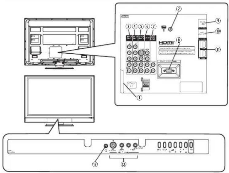
COMPONENT NAMES
Main Unit
Front Panel
text_image
① ② ③ Re ④ Ind ⑤ Ma ⑥ Co ⑦ De ⑧ Sp ⑦ ⑤ ⑥① Cabinet
② Panel
③ Remote Control Receiver
④ Indicating Lamp
⑤ Main Power Switch (on the bottom surface)
⑥ Control Panel and Front Input (see below for details)
⑦ Desktop Stand (option)
⑧ Speaker
Rear Panel

text_image
Technical diagram of a computer monitor rear panel with numbered components and labeled parts① Terminal Board (External Device Connection)
② Power Cord Socket
③ Handgrips
④ Motor Fan
Please refer to 13\~17 for the detailed information for the connections.
Control Panel (including front input)

text_image
APush here to open the door.

A Push the bottom center of the front door to unlock.
B Lift it up from the underside of the door.

text_image
① ② ③ ④ ⑤ ⑥ ⑦ ⑧CAUTION
- Do not place your fingers into the gap at the opened door. If your fingers are caught in the front door, you may be injured.

text_image
Safety warning symbol showing no prohibition above a hand holding a railing, indicating restricted access or anti-protective measures.① Front Input (AV4)
② Menu/Return button
③ Input Select/OK button
④ Volume Down/◄button
⑤ Volume Up/▶ button
⑥ Channel Down/▼button
⑦ Channel Up/▲button
⑧ Sub Power button
COMPONENT NAMES (Continued)
Remote Control
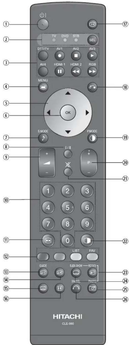
text_image
1 2 3 4 5 6 7 8 9 10 11 12 13 14 15 16 TV DVD STB SEL DTT/TV AV1 AV2 AV3 AV4 HDMI 1 HDMI 2 RGB MENU OK S.MODE PMODE 1 / II + - 1 2 3 4 5 6 7 8 9 0 LIST FAV GUIDE SLIDE SHOW ROTATE SAVE PHOTO HITACHI CLE-980① Sub Power
② Function Select (TV/DVD/STB)
Press this button to select function mode indicating LED lamp. Normally, select "TV".
③ Input Select/DVD Control
Press this button to change input mode. In addition, you can use these buttons while operating the selected brand of DVD player.
④ Menu
⑤ Cursor
⑥ OK
⑦ Sound Mode
Sound mode can be changed each time pressed in the following sequence. Movie→Music→Speech→Favorite
⑧ CHI/II
This is exclusively for TV audio A2/NICAM mode. Also, press this button to select Audio Language in DTT mode.
⑨ Volume Up/Down
⑩ Program Select [Page Select]
Press these buttons to select a TV program directly. For 2 or 3 digits channel selection, press Ⓤ button in advance. Refer to 22 for details.
⑪ Freeze [Hold]
Press this button to change the picture to freeze mode. Press it again to return to normal picture. (Also, it holds the page in teletext mode.)
⑫ Color [Color]
Yellow: It displays program list in DTT mode. It displays favorite list in DTT mode.
⑬ Guide [Index]
It displays EPG screen in DTT mode.
⑭ Time [Cancel]
Press this button to display the time when receiving a TV program. The time is not displayed if the signal received does not have any time information.
⑮ TV/Text [TV⇔Text]
This switches between the TV mode and the mode.
⑯ Zoom [Text⇔TV+Text]
Press this button to change picture size.
⑰ Recall
Press this button to show the input signal status.
⑱ Return
You can use this to return to the previous menu.
⑲ Picture Mode
Picture mode can be changed each time pressed in the following sequence. Dynamic→Natural→Cinema
⑳ Channel Up/Down [Page Select]
⑳ Mute
② Not Available
②3 [Reveal]
⑳ [Subtitle]
It displays subtitle in both TV and DTT mode.
⑳ Not Available
⑳ Not Available
NOTE
Some buttons are only for Teletext mode, and other buttons have different functions in Teletext mode from the use of TV mode. Those buttons are indicated by [ ]. Refer to "Analog Teletext" on 35.
PREPARATION
Remote Control Batteries Installation
This remote control operates on 2 "AA" batteries.
1. Open the battery compartment cover.
- Slide open the battery compartment cover on the backside of the remote control in the direction of an arrow.

2. Install the batteries.
- Install 2 "AA" batteries (included) making sure the polarities match the indication inside the compartment.

3. Close the battery compartment cover.
• To close the battery compartment cover, slide the cover in the direction of an arrow till it clicks shut.

Handling the Remote Control
Use the remote control within about 5m from front of the unit's remote-control sensor and within 30 degrees on both sides.
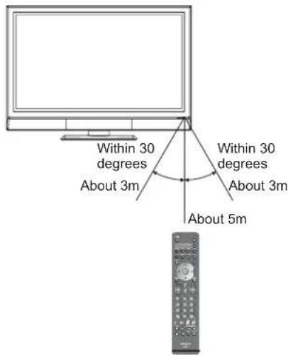
text_image
Within 30 degrees About 3m Within 30 degrees About 3m About 5mCAUTION
It could cause corrosion or battery leakage and may result in physical injury and/or property damage including fire.
- Never mix used and new batteries in the device.
- Replace all the batteries in a device at the same time.
- Remove the batteries if the remote control is not going to be used for an extended period of time.
To avoid possible failure, read the following instructions and handle the remote control properly.
- Do not drop or cause impact to the remote control.
- Do not spill water or any liquid on the remote control.
- Do not place the remote control on a wet object.
- Do not place the remote control under the direct sunlight or near sources of excessive heat.
Caution When Moving the Main Unit
As this product is heavy, whenever it is moved, two people are required to transport it safely. When transferring the unit, hold the unit by using the handgrips at the backside of the panel. (See the figure below for details.)

natural_image
Diagram of hands installing or adjusting a device panel with a tool, no text or symbols presentHandgrips
PREPARATION (continued)
Safety Precaution on Main Unit Installation
Read SAFETY PRECAUTIONS (3 to 6) carefully besides this page.
*When installing the unit, use the optional Desktop Stand (SD9G5000). Please refer to the user manual of the stand. The Desktop Stand (Option) has been used for the illustration in this manual.
When installing the main unit, be sure to use the specified mount units in order to obtain maximum performance and maintain the safety.
We assume no responsibility or liability for personal injuries or property damages caused by use of other mount units or improper installation.
As for the installation instruction, please read each user manual of the mount units: for Desktop Setup, Wall Mounting, and Ceiling Mounting.
In case of using Wall or Ceiling Mounting unit, by contacting your local dealer, ask the specified installation specialist to set up. Never attempt to install it by yourself. It could cause injuries or damages.
Please leave the adequate space around this unit in order to avoid increasing the internal temperature and keep safety.
Make sure not to block any ventilation holes.
Do not install the unit in the small space such as inside the rack, closet or the box.
Leave more than 10cm of clearance from each side of unit and 30cm from the top of unit to wall.
Leave at least 10cm of clearance behind rear unit.

text_image
10cm or more 30cm or more 10cm or more
text_image
10cm or more* Cord or chain ClampAnti-Tumble Measures
Install in a stable place and implement safety measure against overturning.
Securing to a wall or pillar
Using a commercially available cord, chain, and clamp, secure the set to a wall or pillar.

text_image
cord or chain screw hook clamp cord or chain Wall or PillarSecuring to ceiling
Using a commercially available cord, chain, and clamp, secure the set to a ceiling.
NOTE
- For more information regarding the mounting of the unit, please contact your dealer.
- Please install the unit at a proper area where it does not expose anyone to the danger of hitting themselves (for example their hands, head or face, etc) against the edge of the unit and cause personal injury.
CONNECTION
Terminal Positions
text_image
Diagram of a computer setup with labeled components including monitor, home screen, and keyboard interfaceRear
① Power Cord Socket
② Aerial Socket
③ AV1
④ AV2
⑤ AV3
⑥ Monitor Out and Sub Woofer
⑦ PC (RGB)/HDMI Analog Audio Input (See 15)
⑧ Service Use only
⑨ Service Use only
⑩ PC Connection Terminal (D-sub 15 Pin)
⑪ HDMI1 and HDMI2
Front
⑫ AV4
⑬ Headphone Terminal
Connecting Procedure
This unit is ready for various kinds of connections. Make a connection in the following steps. Be sure to turn off the Main Power first when connecting external equipments.
- Connect Power Cord to the rear panel.
- Connect Aerial Lead.
- Connect your external equipments to the unit if any.
- Connect the Power Plug to the Wall Socket.
1. Connecting Power Cord to the Rear Panel
Connect Power Cord to the unit.
*Make sure not to connect the Power Plug to the Wall Socket until all connections are completed.
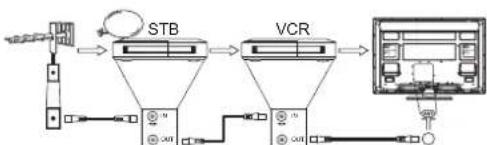
2. Connecting Aerial Lead.
There are two ways to connect Aerial Lead.
① When you do not have any other external equipment: Connect the Aerial Lead directly into the Socket at rear panel.
② When you have one or more external devices to connect:
-
Use RF cable to connect between each equipment and Antenna.
-
Connect the Aerial Lead to an equipment 'In' Socket marked
-
Connect the RF cable from the equipment 'Out' to the other equipment 'In.'
-
Then, connect from the equipment 'Out' to "ANT" on the plasma screen Socket on marked .

flowchart
graph LR
    A["Input Signal"] --> B["STB"]
    B --> C["VCR"]
    C --> D["Computer Interface"]
    D --> E["USB Cable"]
    E --> F["USB Cable"]
    F --> G["USB Cable"]
    G --> H["USB Cable"]
    H --> I["USB Cable"]
    I --> J["USB Cable"]
    J --> K["USB Cable"]
    K --> L["USB Cable"]
    L --> M["USB Cable"]
    M --> N["USB Cable"]
    N --> O["USB Cable"]
    O --> P["USB Cable"]
    P --> Q["USB Cable"]
    Q --> R["USB Cable"]
    R --> S["USB Cable"]
    S --> T["USB Cable"]
    T --> U["USB Cable"]
    U --> V["USB Cable"]
    V --> W["USB Cable"]
    W --> X["USB Cable"]
    X --> Y["USB Cable"]
    Y --> Z["USB Cable"]
[Example: Connecting Antenna through STB and VCR]
Precautions when connecting the aerial
- Please use a coaxial cable which is free from interference to connect the aerial. Avoid using a parallel flat feeder wire as interference may occur, causing reception to be unstable and stripe noise to appear on the screen.
- Avoid using indoor aerial as this may be affected by interference. Please use CATV net or outdoor aerial.
- For safety, install an external aerial conforming to AS1417.1.
- If noise appears in the picture of VHF-Low band channel, please use a double-shielded cable (not provided) for RF LEADS to reduce the noise.
CONNECTION (continued)
Connecting Procedure (continued)
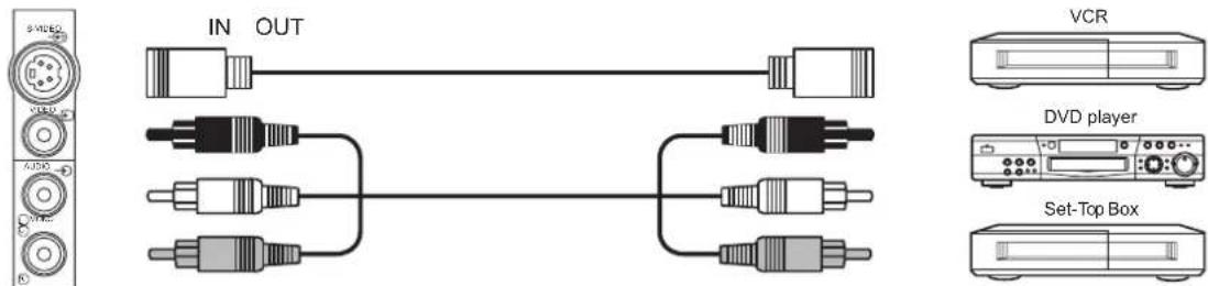
3. Connecting to External Equipment
• Terminals on Rear
AV1 and AV2 can be connected to the equipment with either Component or Composite output. Depending on whether the Y/VIDEO input of your selected equipment is Y signal or Video signal, it automatically regards as Component or Composite. When using as Composite, do not insert the jacks into P_B or P_R .

text_image
IN OUT [Example] VCR DVD player Set-Top Box
If your external device has a Component terminal, COMPONENT connection is recommended for higher quality picture.
AV3 can be connected to the equipment with an S-Video output and Composite output.
[Example]
text_image
IN OUT VCR DVD player Set-Top Box
If your external device has a S-video terminal, S-VIDEO connection is recommended for higher quality picture.
NOTE
- If both S-video and video input terminals of AV3 are connected at the same time, S-video will have its priority.
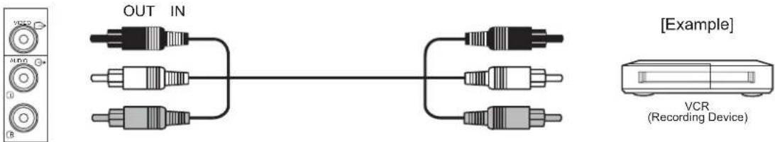
Monitor Out can be used to display same image as main unit on another monitor.
When this output terminal is connected to an external monitor with a 75 Ohm terminal, the same image from composite(AV1\~4), S-Video(AV3,4), or RF (including DTT) signal can be displayed to the external monitor.
text_image
OUT IN [Example] VCR (Recording Device)NOTE
• Video output is not available from component, RGB, or HDMI input.
- Audio output is not available when HDMI-HDMI cable is connected.
Sub Woofer terminal can bring the deep bass sound from the external speaker.
[Example]

text_image
OUT IN orCONNECTION (continued)
Connecting Procedure (continued)
PC terminal (D-sub 15 pin) + PC (RGB)/HDMI Analog Audio Input terminal are connected to PC, which allows Analog RGB signal.
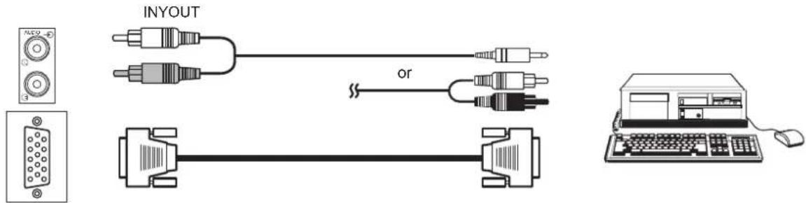
text_image
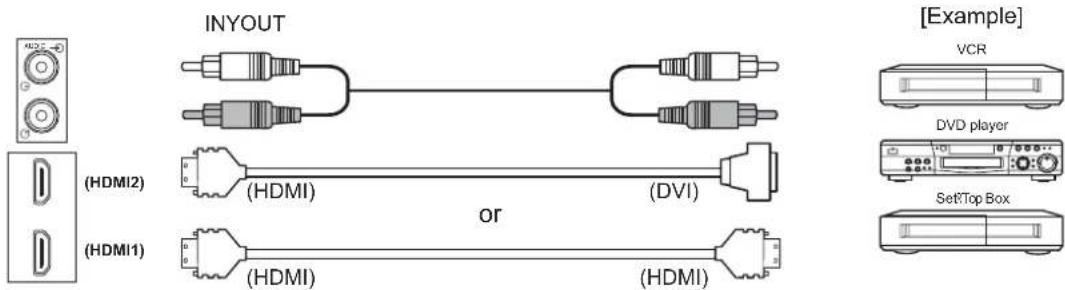
INYOUT orHDMI 1·2 terminals can be connected to the devices with HDMI output.
If the external device has DVI output, this can be available with HDMI-DVI cable. In case of using the HDMI-DVI cable, connect analog audio signal to PC (RGB)/HDMI Analog Audio Input terminal.
text_image
INYOUT (HDMI2) (HDMI1) (HDMI) (HDMI) (DVI) (HDMI) or (HDMI) [Example] VCR DVD player SetTop Box
Information
HDMI (High Definition Multimedia Interface) is next-generation multimedia I/O interface. Only one cable is used to transmit all video/audio/control signals, which creates easy connection.
Moreover, those digital signals can produce high quality data without any degradation.
You are provided with two HDMI terminals, one of the most remarkable features.

If your external device has a HDMI terminal, HDMI connection is recommended for higher quality picture and sound.
NOTE
• PC (RGB)/HDMI analog audio input terminal
This terminal can be used in one of the following cases only.
① The external device is connected to the PC (RGB) terminal of the TV.
② The DVI output of an external device is connected to the HDMI1 terminal using the HDMI-DVI cable.
③ The DVI output of an external device is connected to the HDMI2 terminal using the HDMI-DVI cable.
Make sure that the video and audio terminals are connected to the same external device.
About the output format of an external device, refer to "Recommended Signal List" on 56.

text_image
PC (RGB) Terminal HDMI2 Terminal HDMI1 Terminal PC (RGB)/HDMI Analog Audio Input TerminalCONNECTION (continued)
Connecting Procedure (continued)
• Terminals on Front
Since the following terminals are located on the front, it is very convenient to connect an extra device on a temporary basis after completing the connections on the rear panel.
AV4 can be connected to the equipment with S-Video output and composite output.
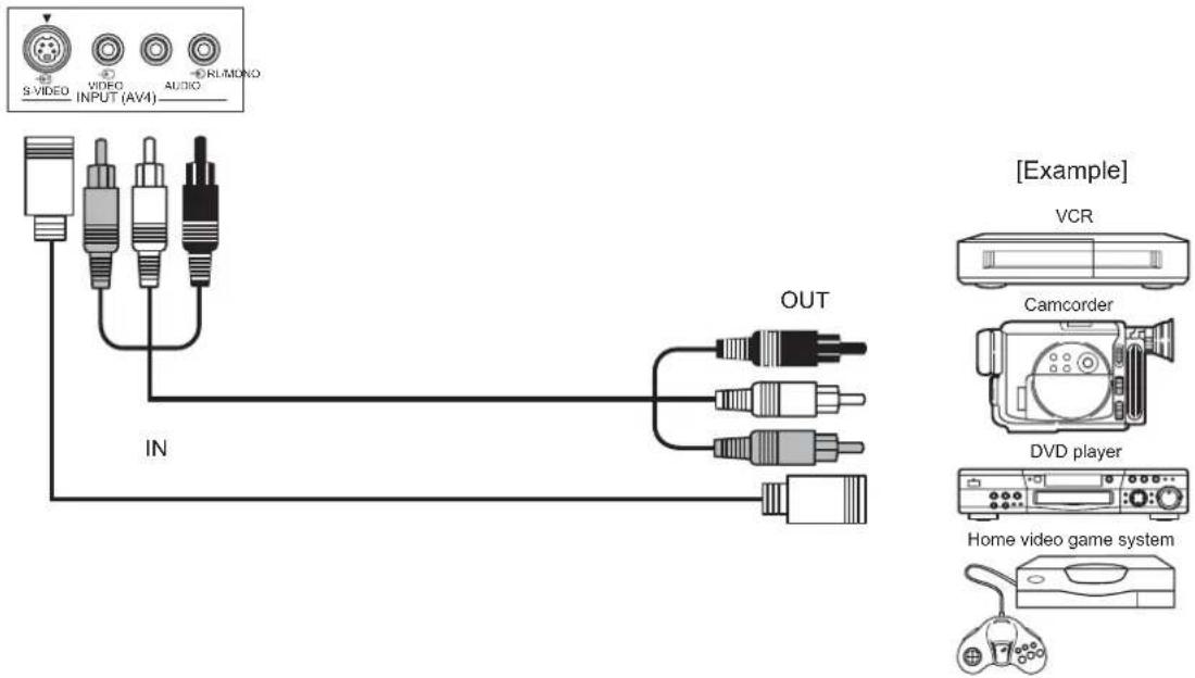
text_image
S VIDEO VIDEO INPUT (AV4) AUDIO RUMONO IN OUT [Example] VCR Camcorder DVD player Home video game systemIf your external device has S-video terminal, S-VIDEO connection is recommended for higher quality picture.
NOTE
- If both S-video and video input terminals of AV4 are connected at the same time, S-video will have its priority.
Headphone The detail settings can be adjusted from Audio Menu on page 33.
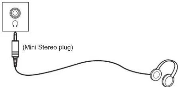
text_image
(Mini Stereo plug)The audio from the speaker will be muted when connecting the headphone to this terminal.
CONNECTION (continued)
Connecting Procedure (continued)
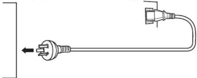
4. Connecting the plug into the wall socket
Connect the Power Cord after completing all other connections. (The type of plug is different from this drawing.)
natural_image
Pure electrical circuit lines without any symbolsCAUTION
- Use only the Power Cord provided.
- Do not use a power supply voltage other than that indicated(AC240V, 50Hz). It may cause fire or electric shock.
- For the plasma television, a three-core power cord with a ground terminal is used for efficiency protection. Always be sure to connect the Power Cord to a three-pronged grounded outlet and make sure that the cord is properly grounded. If you use a power source converter plug, use an outlet with a ground terminal and screw down the ground line.
- Ensure that both ends of power cord are easily accessible.
- If you have to change the power cord, please use the certified power cord that meets your region's safety standard.

Information
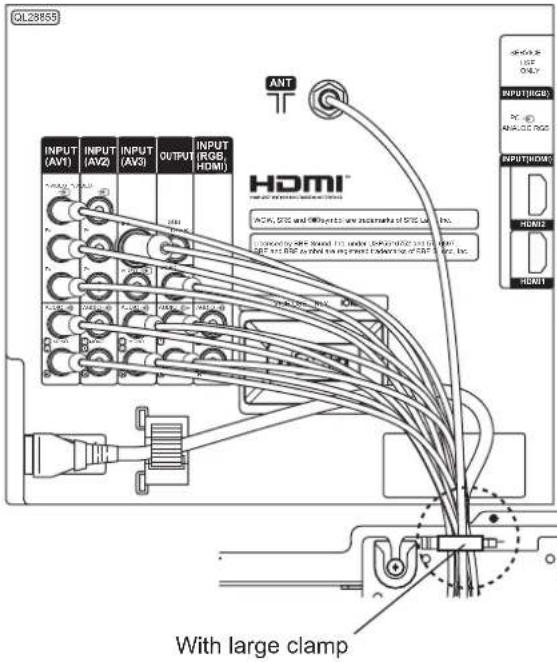
• How to secure the cables.
After connecting all of the cables to the terminals, secure them with the clamp. When you secure the cables, please be careful not to tighten too much.
text_image
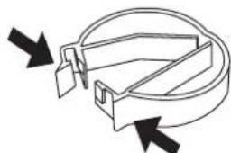
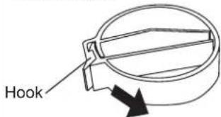
QL2855 INT HDMI INPUT (AV1) INPUT (AV2) INPUT (AV3) OUTPUT INPUT (RGB, HDMI) HDMI ACM, SCS and @Input to any instance of SCS, Inc. Annotated by SPF, Sound, Inc. under, performance and in-line port. SAP and RSP as shown for the shipment end-to-end of SPF, Inc. With large clampHow to clamp:
• To set
natural_image
Pure mechanical component diagram without any text, numbers, or symbolsSet the clamp in the direction of the arrow.
• To unfasten
text_image
HookLoosen the hook, and pull in the direction of the arrow.
BASIC OPERATION
Power On/Off
Now, turn On the main power to the unit. Make sure that the Power Cord has plugged into the wall socket.
• To turn On the power of the unit:
- Press the Main Power switch on the unit.
• The Indicating Lamp will illuminates in Red (Standby mode).
- Press Sub Power button either on the control panel or on the remote control.
- The color of the Indicating Lamp turns into Green, and the image will display on the screen.
• To turn Off the power of the unit:
- Press Sub Power button either on the control panel or on the remote control.
- The image disappears from the screen and the Indicating Lamp turns into Red (Standby mode).
- Press Main Power switch to completely turn Off the power of the unit.
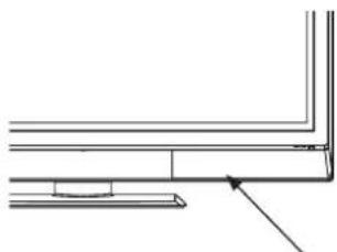
natural_image
Pure technical line drawing of a corner joint or bracket (no text or symbols)Main Power switch (on the bottom surface)
Sub Power button
text_image
OK F OKSub Power button
The Indicating Lamp Status Check
| Indicating Lamp Status | Power Status Power Switch Status | |
| Off | Off | Main power → Off |
| Red Standby mode | Main power → OnSub Power button → Off | |
| Green On | Main power → OnSub power button → On | |
| Orange | Power Save mode* | Main power → OnSub Power button → On |
*About Power Save mode, see "Power Save Mode" and "When Following Messages Appear on the Screen" on 49 and 51 for details.
NOTE
- If the image does not appear on the screen at all, or have any problem, see TROUBLESHOOTING on 51\~53. It may help you to solve the problems.
- You can turn ON the power only by pressing the Sub Power button during the Standby mode.
- Do not switch the power On/Off repeatedly in a short period of time. It could cause malfunction.
- To avoid sudden surges of electricity when the power comes back on, turn Off the main power of the unit before you leave if there is a power cut during use of the unit.
BASIC OPERATION (continued)
First Time Setup
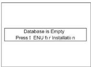
When you turn ON the TV for the first time, a message shows up to lead to the DTT channel installation.
- The message "Database is Empty Press MENU for installation" appears.
- Press 📄 button to access DTT main menu.
- Select "Installation" from DTT main menu and press OK button.
- The password box will appear as "****", and enter "0000" as your initial password.
- Select one of the scanning method from "Manual scan", "Quick scan", or "Auto scan."
NOTE
- "Quick scan" and "Auto scan" are easier methods for the first time. See 37 for the details.
- Use 📄 button to go back a previous menu condition, and use ⏱ button to return to the DTT main menu.
text_image
Database is Empty Press ! ENU for Installation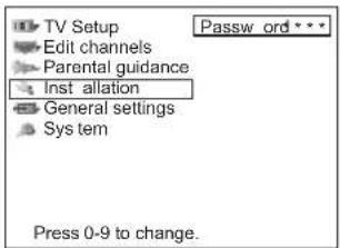
text_image
TV Setup Edit channels Parental guidance Inst allation General settings Sys tem Press 0-9 to change.Volume UP/DOWN
- To increase the sound volume, press + button on the remote control, or Volume Up button on the control panel.
• The Volume Indicator value on the screen will shift right. - To decrease the sound volume, press ▼ button on the remote control or Volume Down button on the control panel.
• The Volume Indicator value on the screen will shift left.
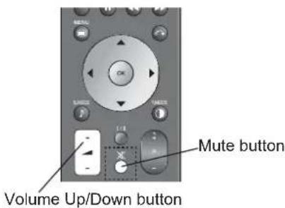
text_image
MUTE button Volume Up/Down buttonMute
- To mute the sound, press ✗ button on the remote control.
• The sound of the unit is temporarily turned Off.
- The color of the Volume Indicator will turn into magenta while muting the volume.
- To turn the sound back, press ✕ button again, or Volume Up button on either remote control or the control panel.
• The color of the Volume Indicator will turn back to green.
NOTE
- You can decrease the volume by pressing ▶ button while the sound is muted.
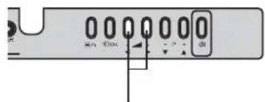
text_image
0 0 0 0 0 0 0 - 0 0 0 0 0 0 0 - 0 0 0 0 0 0 0 - 0 0 0 0 0 0 0 - 0 0 0 0 0 0 0 - 0 0 0 0 0 0 0 - 0 0 0 0 0 0 0 - 0 0Volume Up/Down button
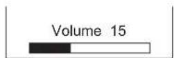
The Volume Indicator
BASIC OPERATION (continued)
Input Switching to DTT/TV, AV1\~4, HDMI, and RGB
By pressing Input Select button, you can switch the input.
- To watch actual broadcast, press Input Select button on the control panel, the numeric buttons or Channel Up/Down button on the remote control.
-
To display the image outputting from the external equipments connected to each terminal (DTT, TV, AV1\~4, HDMI 1, 2, and RGB), select corresponding mode.
-
Press Input Select buttons on the remote control.
(Use ○ button to switch between DTT and TV mode.)
- The Input modes can be also switched by using Input Select button on the control panel.
Each time this button is pressed, the screen displays corresponding mode by following order.

- To directly go back to TV mode, pressing channel Up/Down buttons on either remote control or the control panel.
Also, you can use the numeric buttons on the remote control.
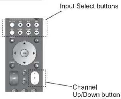
text_image
Input Select buttons Channel Up/Down button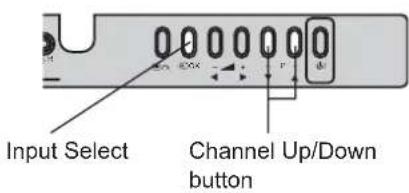
text_image
Input Select Channel Up/Down buttonInput Signal Screen Display
The input signal status can be displayed on the screen by pressing the Ⓐ button of the remote control.
- The display in DTT mode will appear as changing the channels and go out in set time. (Refer to 40)
- The display in TV/Video/RGB mode will go out in approximately 6 seconds.

text_image
DTT Channel name 06-0072 Now SD C ABCDE Program name Broadcasting time Start time End time Station name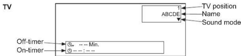
flowchart
graph TD
    A["Off-timer"] --> B["On-timer"]
    B --> C["1 ABCDE"]
    C --> D["TV position"]
    C --> E["Name"]
    C --> F["Sound mode"]

flowchart
graph LR
    A["AV1 Component 720p"] --> B["Input mode"]
    A --> C["Signal mode"]
    A --> D["Signal format*"]
    E["Off-timer"] --> F["Min."]
    G["On-timer"] --> H["---"]
    I["*Component/HDMI only"]
text_image
RGB RGB H : 48.4kHz V : 60.1 H Input mode Input horizontal frequency Input vertical frequency Off-timer --- Min. On-timer --- : ---
text_image
d1 RECALL button HITACHI CLASHTV SETUP OPERATION
How to use the On-Screen Display (OSD) system
With the On-Screen Display system, you can access the various kinds of the features and functions in this product.
- Basic Operation
- Press ☐ button on the remote control or Menu button on the control panel of the unit. The Main Menu is displayed on the screen as shown on the right.
- To select the item, press ⬆ button. The selected item will be highlighted in Green.
- Press OK button to set your selection. The selected menu page will be displayed on the screen.
- Use ⏻ button to choose the item on the MENU page. Press ⏻ button to set your selection.
- Use ▶ button to adjust the item values or choose options. Press OK button to set your selection.
- To exit from the menu, press MENU button.
NOTE
- The OSD menu screen will be closed automatically when no operation has been made for about one minute.
- If the item in menu is shown in gray, it means that it cannot be selected or adjusted.
text_image
Picture Audio Timer Function Setup Select OK Set
text_image
Menu button
text_image
0 0 0 0 0 0 0 ← + - → - → + → d1Menu button
TV SETUP OPERATION (continued)
Setup Menu (TV mode)
With this menu, you can access various kinds of features relating to TV channel settings.
text_image
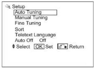
Setup Auto Tuning Manual Tuning Fine Tuning Sort Telatext Language Auto Off Off Select OK Set Return| Selected Items Setup hint | |||
| Auto Tuning | Mode | Position | Select the way to display the channels on the screen between “--”, “----”, “-” and AV00 by using ⏻ button.“--” is for 2 digits channel selection,“----” is for 3 digits channel selection, and“-” is for 1 digit channel selection.The position numbers are displayed on the upper right corner of screen.(1~199, AV00) |
| Direct | The channel number 1~99 are displayed as C* *, and the channel number 101~199 are displayed as S* *. | ||
| Search | Tune the local channels automatically.Press ⏻ button to start searching. | ||
| Manual Tuning | Position | Press channel up (+) down (-) buttons to input position number (1~199, AV00) or channel number (C* * or S* * | |
| Frequency | When Auto Tuning Mode is set to [position], search the frequency by using ⏻ button. | ||
| When Auto Tuning Mode is set to [Direct], this function is not available (grayed out). | |||
| Name | 1. Move the cursor to the first digit and select the letters with ⏻ button.2. Move to the next digit with ▶ button.3. Press ⏻ button again when you finish inputting all the letters.• The selectable letters are as follows: “0”~“9”, “A”~“Z”, “+”, “” (blank), “-” (displayed as blank), and “.” (period). | ||
| Sound System | Auto | Select the sound system from 5 different modes. | |
| M | |||
| BG | |||
| I | |||
| DK | |||

Information
- Use AV00 when connecting equipment such as a VCR via an RF (aerial type) cable.
TV SETUP OPERATION (continued)
Setup Menu (TV mode) (continued)
| Selected Items Setup hint | |||
| Manual Tuning | Color System | Auto | Select color system from 5 different modes. |
| PAL | |||
| SECAM | |||
| NTSC 4.43 | |||
| NTSC 3.58 | |||
| Skip | Off | It allows you to skip unregistered channels automatically when you use channel up (+) down (-) buttons to select channels.This function will automatically skip unavailable channels when set to on. | |
| On | |||
| NR | Off | The noise on the screen or interference could be reduced, especially at the area of weak electric field. | |
| On | |||
| Antenna Att. | Off | The noise on the screen or interference could be reduced in case that the receiving airwaves are too strong.• The selection on this item is applied to all the channels. | |
| On | |||
| Fine Tuning -56~+56 | ►: Increase the frequency data for the main tuner.◄: Decrease the frequency data for the main tuner. | ||
| Sort | You can change the order of channels as follows.1. Move the cursor to the channel row you want to change order and then, press ⏻ button.2. The color of the letters on the designated line will be turned into green bracket and with [ ].3. Move the designated row by using ⏻ button.4. Press ⏻ button to fix the position.• This function is not available (grayed out) when the Auto Tuning Mode is set to [Direct]. | ||
| Teletext Language | Select Teletext Language from 5 different categories (West Europe, East Europe, Russian, Arabic and Farsi) according to the area.Example:West Europe : Asian countries where the Teletext is broadcasting in English such as Singapore, Australia, and Malaysia.East Europe : Poland, Sweden, HungaryRussian : RussiaArabic : Arab countriesFarsi : Iran | ||
| Auto Off | Off | When no airwave has been received and no operation has been made for 10 minutes in TV mode, it turns to standby mode automatically. | |
| On | |||
TV SETUP OPERATION (continued)
Setup Menu (AV mode)
With this menu, you can select or adjust the condition of the input signals from each terminal.

text_image
Setup System System 1 Color System Select Set Return| Selected Items Setup hint | ||||
| System | System 1 | Do not change the original setting.(System1: Europe/Asia, System2: South America)• Composite and S-video input only. | ||
| System 2 | ||||
| Color System | AV1~AV4 | System 1 | Auto | Select the color system depending on the input signal.Generally, select [Auto] to receive all signals for both System1 and System2.In case that the input signal has too much noise, the signal level is too low, or the operation is unstable in [Auto], select the system according to the color system of the input signal.Composite and S-video input only. |
| PAL | ||||
| SECAM | ||||
| NTSC 4.43 | ||||
| NTSC 3.58 | ||||
| PAL60 | ||||
| System 2 | Auto | |||
| NTSC-M | ||||
| PAL-M | ||||
| PAL-N | ||||
TV SETUP OPERATION (continued)
Setup Menu (RGB mode)
With this menu, you can adjust the display condition of the image which is inputting from the RGB terminals. By pressing ▼ button at the bottom of the 1st Setup menu page, the 2nd Setup menu page will appear on the screen.
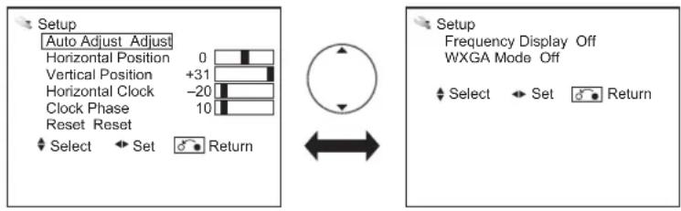
text_image
Setup Auto Adjust Adjust Horizontal Position 0 Vertical Position +31 Horizontal Clock -20 Clock Phase 10 Reset Reset Select Set Return Setup Frequency Display Off WXGA Mode Off Select Set Return| Selected Items Setup hint | ||
| Auto Adjust | Adjust Horizontal Position, Vertical Position, Horizontal Clock, and Clock Phase automatically.·Press OK button to start auto adjustment.The message “Auto Adjusting” is displayed.·Depending on the type of the signal, there is a possibility that the display may not be adjusted in its optimum condition with this function. In that case, please adjust each item manually. | |
| Horizontal Position* | -63~+63 | Adjust the display position horizontally.·When the position exceeds the possible range, the display color will turn into Magenta. |
| Vertical Position* -31~+31 | Adjust the display position vertically.·When the position exceeds the possible range, the display color will turn into Magenta. | |
| Horizontal Clock* | -31~+31 | Minimize the vertical stripes on the screen. |
| Clock Phase* 0~63 | Minimize the blurring of the letters and stripes on horizontal row.·Make sure to adjust Horizontal Clock first before adjusting Clock Phase. | |
| Reset | Reset all the set values on this Menu page to original factory settings. | |
| Frequency Display | Off | Select whether indicating the PC signal frequency information on Input Signal Screen Display or not. |
| On | ||
| WXGA Mode | Off | ·This function is available only for WXGA signal.·Refer to “Recommended Signal List” on 56. |
| 1280x768 | ||
| 1366x768 | ||

Information
- The items indicated by “*” can be automatically stored depending on the signal mode.
- The signal mode is identified by the Horizontal/Vertical frequency and the sync. signal polarity, which has almost same values in all the above items might be regarded as the same signal.
- The item "Auto Adjust" cannot be stored. Press OK to start auto adjustment as needed.
TV SETUP OPERATION (continued)
Function Menu
This menu provides various ways to protect your panel, reduce power consumption, and set up utilizing the useful functions, such as Freeze Mode.

text_image
Function Screen Saver Off Screen Wipe On 60Min. Black Side Panel Off Video Power Save Off Freeze Mode tSplit Default Zoom Panoramic Eco Mode TOn Picture Size 1 Reset tReset Select Set Return| Selected Items Setup hint | ||
| Screen Saver | Off | This helps to reduce image retention by shifting the whole picture (in small amounts) around the screen at set intervals.You can select the interval between each shift. |
| 5Min. | ||
| 10Min. | ||
| 20Min. | ||
| 40Min. | ||
| 60Min. | ||
| Screen Wipe | On | This displays the white pattern to reduce the image retention.• On: Continuous Operation• 60Min.: Limited Operation for 60 minutes. After 60 minutes, TV goes to standby mode. |
| 60Min. | ||
| Black Side Panel | Off | This can change the color of sidebars showing up in normal mode. (Off:gray, On:black)It is recommended to set Off to reduce image retention.This cannot be stored. (The default setting is off.) |
| On | ||
| Video Power Save | Off | During AV input, this helps to reduce power consumption when there is no video signal. In case of selecting AV input terminal which does not have signal input, it changes the power status to power save mode in AV1/AV2 and standby mode in other AV input. (See 49 in details.) |
| On | ||
| Freeze Mode | Single | This is the useful function to watch the program in a still picture. (See 47 in details.)• Single: full-sized image• Split: half-sized images (One is still, while the other is active.) |
| Split | ||
| Default Zoom | Panoramic1 | You can set the display size for TV input screen appearing first when turning the main power On. |
| Panoramic2 | ||
| 4:3 | ||
| Full | ||
| Eco Mode | Off | This can reduce the power consumption. |
| On | ||

Information
- The item "Screen Wipe" cannot be stored.
Select "On" or "60 Min." to conduct this function as needed.
NOTE
Refer to 7 about image retention.
TV SETUP OPERATION (continued)
Function Menu (continued)
| Selected Items Setup hint | ||
| Picture Size | 1 | In case that the image from TV signal (especially CATV) has a blackened gap in either or both side during Panoramic mode, select [2] so that it can make up for the gap.This is not available when displaying “Cinema” size.This is not available except RF, composite, and component (576i,480i) input. (gray out) |
| 2 | ||
| Reset | Each item on this menu screen can be restored to the original factory settings by pressing ⏻ button. | |
TV SETUP OPERATION (continued)
Picture Menu (TV/AV mode)
In this menu, you can make specific adjustments for the picture based on your preference.
By pressing ▼button at the bottom of each menu page, the next Picture menu page will appear on the screen.
text_image
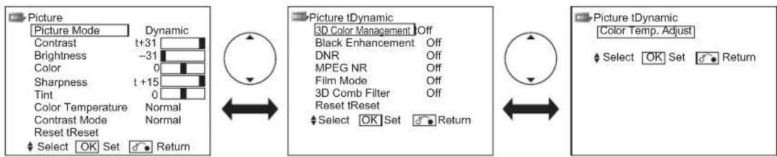
Picture Picture Mode Dynamic Contrast t+31 Brightness -31 Color 0 Sharpness t +15 Tint 0 Color Temperature Normal Contrast Mode Normal Reset tReset Select OK Set Return Picture tDynamic 3D Color Management Off Black Enhancement Off DNR Off MPEG NR Off Film Mode Off 3D Comb Filter Off Reset tReset Select OK Set Return Picture tDynamic Color Temp. Adjust Select OK Set Return| Selected Items Setup hint | ||
| Picture Mode | Dynamic | You can make the best selection from 3 modes depending on the lighting condition and intended use.Dynamic: Suitable for the brighter conditions.Natural : Suitable for the normal lighting condition.Cinema : Suitable for watching movie. |
| Natural | ||
| Cinema | ||
| Contrast* | -31~+31(+32~+40) | This adjusts the contrast to meet the lighting environment by using button.The maximum value can be extended to [+40] by pressing and holding button at [+31], which changes the color between those numbers from green to magenta. This is the special feature prepared for the dark scene. At the normal condition, it is recommended to set the value less than [+31]. |
| Brightness* -31 | ~+31 | With this function, black is adjusted to change the overall brightness by using button. |
| Color* -31 | ~+31 | It can adjust color density based on your preference by using button. |
| Sharpness* -15 | ~+15 | Preferred sharpness can be adjusted by pressing button for Softer image or button for Sharper image. |
| Tint* -31 | ~+31 | Pressing button enhances red and weakens green, while pressing button weakens red and enhances green. The setup hint is adjusting for the realistic skin color. |
| Color Temperature* | Cool | You can select from 3 settings (default) depending on the color condition with button. |
| Normal | ||
| Warm | ||
| Contrast Mode* | Dynamic | It allows you to choose from 3 modes.Dynamic: Sharpen the gradation to improve the contrast feeling.Normal: Reproduce as faithful gradation as possible.Low: Weaken the graduation to reduce the contrast feeling. |
| Normal | ||
| Low | ||
| Reset | Each item on this menu screen can be restored to the original factory settings by pressing button. | |
TV SETUP OPERATION (continued)
Picture Menu (TV/AV mode) (continued)
| Selected Items Setup hint | ||
| 3D Color Management* | Off | On: It automatically adjusts the suitable tint, color density, and brightness on images.Off: Set it off if the image does not look natural. |
| On | ||
| Black Enhancement* | Off | Adjusts the black level compensation. |
| Low | ||
| Middle | ||
| High | ||
| DNR* | Off | This is a noise reduction system for picture signal. |
| Low | ||
| Middle | ||
| High | ||
| MPEG NR* | Off | This is a noise reduction system for MPEG picture signal.(ex. against mosquito noise and block noise.) |
| Low | ||
| High | ||
| Film Mode* | Off | On: Automatically identify if it is the movie film and faithfully reproduces the original film images.Off: Set to Off if the image does not look natural. |
| On | ||
| 3D Comb Filter* | Off | This is available only when receiving NTSC/PAL composite signal. This reduces the dot and color blurring in minute scales so that it can reproduce purer color.This is not available for NTSC4.43, PAL60, PAL-N, and PAL-M system. |
| Low | ||
| Middle | ||
| High | ||
| Reset | Each item on this menu screen can be restored to the original factory settings by pressing ⏻ button. | |
TV SETUP OPERATION (continued)
Picture Menu (TV/AV mode) (continued)
| Selected Items Setup hint | |||
| Color Temp. Adjust* | On | Amplitude | On: When you want to set specific adjustments in each of the 3 Color Temperature modes. You can adjust on the amplitude and cut off. The settings reflect on the Color Temperature.Amplitude: subdue the following colors on the brighter parts. (-63~0)Cut off : subdue the following colors on the darker parts. (-31~+31)Off: Remains as default setting. |
| Red** | |||
| Green** | |||
| Blue** | |||
| Cut off | |||
| Red** | |||
| Green** | |||
| Blue** | |||
| Off | |||

Information
The items indicated by “*” can be stored for each of inputs and picture modes (Dynamic/Natural/Cinema). You can enjoy different setting depending on the selected input such as VCR in AV1.
In addition, the item indicated by “**” can be stored for each of color temperature modes.
TV SETUP OPERATION (continued)
Picture Menu (RGB mode)
In this menu, you can make specific adjustments for the RGB picture based on your preference.

text_image
Picture Contrast : + 31 Brightness : -31 Color : 0 Tint : + 31 Color Temperature : Normal Color Temp. Adjust Reset Reset Select OK Set Return| Selected Items Setup hint | ||
| Contrast | -31~+31(+32~+40) | This adjusts the contrast to meet the lighting environment by using ◀ button.The maximum value can be extended to [+40] by pressing and holding ▶ button at [+31], which changes the color between those numbers from green to magenta. This is the special feature prepared for the dark scene. At normal condition, it is recommended to set the value less than [+31]. |
| Brightness -31~+31 | Adjust according to personal preference by using ◀ button. | |
| Color -31~+31 | Adjust according to personal preference by using ◀ button. | |
| Tint -31~+31 | Pressing ◀ button enhances red and weakens green, while pressing ▶ button weakens red and enhances green. The setup hint is adjusting for the realistic skin color. | |
| Color Temperature | Cool | You can select from 3 settings (default) depending on the lighting condition with ◀ button. |
| Normal | ||
| Warm | ||
TV SETUP OPERATION (continued)
Picture menu (RGB mode) (continued)
| Selected Items Setup hint | |||
| Color Temp. Adjust. | On | Amplitude | On: When you want to set specific adjustments in each of the 3 Color Temperature modes. You can adjust on the amplitude and cut off. The settings reflect on the Color Temperature.Amplitude: Subdue the following colors on the brighter parts. (-63~0)Cut off : Subdue the following colors on the darker parts. (-31~+31)Off: Remains as default setting. |
| Red* | |||
| Green* | |||
| Blue* | |||
| Cut off | |||
| Red* | |||
| Green* | |||
| Blue* | |||
| Off | |||
| Reset | Each item on this menu screen can be restored to the original factory settings by pressing OK button. | ||

Information
The item indicated by “*” can be stored for each of color temperature modes.
TV SETUP OPERATION (continued)
Audio Menu
With this menu, you can adjust and customize the audio condition as you like. You can move on to the next menu screen by pressing ▼ button at the bottom.
text_image
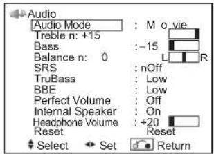
Audio Audio Mode : M o vie Treble n: +15 Bass : -15 Balance n: 0 SRS : nOff TruBass : Low BBE : Low Perfect Volume : Off Internal Speaker : On Headphone Volume : +20 Reset : Reset Select Set Return| Selected Items Setup hint | ||
| Audio Mode | Movie | You can select the most suitable sound condition from 4 alternatives according to the contents.If you want to adjust each item value based on your preference, select “Favorite”. |
| Music | ||
| Speech | ||
| Favorite | ||
| Treble* | -15~+15 | Adjust the Treble. |
| Bass* | -15~+15 | Adjust the Bass. |
| Balance -10~+10 | Adjust the balance of the sound from right and left speakers. | |
| SRS* | Off | This system gives you the dynamic 3D sound. |
| On | ||
| TruBass* | Off | TruBass gives you the enhanced bass sound.Select it depending on your preference. |
| Low | ||
| High | ||
| BBE* | Off | BBE High Definition Sound restores clarity and presence for better speech intelligibility and musical realism.Select it depending on your preference. |
| Low | ||
| High | ||
| Perfect Volume | Off | It will automatically adjust the volume to its average level each time you change the channel. |
| On | ||
| Internal Speaker | Off | This needs to be switched to Off when you want to take audio from external equipment.It is normally set to On when you operate the set using the built in speakers. |
| On | ||
| Headphone Volume 0~63 | It allows you to adjust the volume of the headphone.The sound from the speaker will automatically set to MUTE when the headphone is connected to the terminal. | |
| Reset | Reset all the set values on this Menu Page to the original factory settings. | |

Information
The items indicated by “*” can be stored for each of Audio Mode.
TV SETUP OPERATION (continued)
Timer Menu
This allows the unit to turn Off (Standby mode) or On at set time automatically, which you may find useful.

text_image
Timer Off Timer : 30Min. On Timer : --:-- Select ▶Adjust ●Return| Selected Items Setup hint | ||
| Off Timer | --Min. | This function automatically sets the power to Standby mode when the selected time period has elapsed. |
| 30Min. | ||
| 60Min. | ||
| 90Min. | ||
| 120Min. | ||
| On Timer --:-- | This function automatically sets the power from standby mode to On when the specified time period has elapsed. After the “On Timer” is set, the indicating lamp will start blinking.Input the desired time within the range of 00:01 to 11:59 by using ⏻ button on the remote control. | |
TV SETUP OPERATION (continued)
Analog Teletext
• What is "Teletext"
Teletext is the written information services provided by each TV channel. Most TV channels provide information via Teletext such as:
text_image
nel. Page Number 11 : 37 : 56 Link pages Red Green Yellow Blue• TV program schedule
- Weather forecasts
- Sports results
- Newsflash
• How to operate the Teletext
You can display the Teletext simply by pressing the remote control buttons.
NOTE
Select Teletext language from Setup Menu shown on 23.
| Operation Press | |
| To activate Teletext mode.To exit from the Teletext mode. | [Z6DD][TV ⇔ Text] |
| To move to the next or previous page. |  [Page Select] [Page Select] |
| To jump to the indicated page. | 0  9[Page Select] 9[Page Select] |
| To split the screen into two and watch both Teletext information and actual broadcast at the same time.Press again to watch Teletext on a single screen. | [SKAY][Text ⇔ TV+Text] |
| To display Index page. | [SSDY][Index] |
| To access Subtitle service directly (if the channel has the Subtitle service broadcasting). | [AX7B][Subtitle] |
| To display Hidden text.ex. The answers of the Quiz or the Game page.Press again to close the revealed answer. |  [Reveal] [Reveal] |
| To return to actual broadcast temporarily while searching for the Teletext page you request.When the search is done, the designated page # will be displayed on the upper left of the screen.Press again to return to Teletext page. |  [Cancel] [Cancel] |
| To access the link pages which are displayed at the bottom of the page. (Select the buttons corresponding to the colors of the letters on screen.) | YZBD [Color] |
| To hold the text picture. | [TT7A][A4BS] |

text_image
TV DVD S7B NOT AV1 RW2 AV3 AV4 HOME1 HOME 2 RGB MENU OK SWOCK P - 1 2 3 4 5 6 7 8 9 0 LIST FIN SUEK SEEACH — USB HUAU HUAU HUAU HUAU HUAU HUAU HUAU HUAU HUAU HUAU HUAU HUAU HUAU HUAU HUAU HUAU HUAU HUAU HUAU HUAU HUAU HUAU HUAU HUAU HUAU HUAU HUAU HUAU HUAU HUAU HI TAI HUA U U U U U U U U U U U U U U U U U U U U U U U U U U U U U U U U U U U U U U U U U U U U U U U U U U U U U U U U U U U U U U U U U U U U U U U U U U U U U U U U U U U U U U U U U U U U U U U U U U U U
Information
• Each time the Ⓗ button is pressed, the screen will be switched from double screen to signal screen.
- Some Teletext pages do not display Link Pages at the bottom of the screen. Press 📄 button to display them.
NOTE
- Teletext function is different between Analog and Digital. Refer to 40 about Digital Teletext.
DIGITAL TERRESTRIAL TELEVISION (DTT) OPERATION
How to use the On-Screen Display (OSD) system
With the On-Screen Display system, you can access the various kinds of the features and functions.
- Basic Operation
-
Press 📄 button on the remote control or Menu button on the control panel of the unit. The DTT Main Menu is displayed on the screen as shown on the right.
-
To select the item, press ⬆ button. The selected item will be highlighted.
-
Press OK button to set your selection. The selected menu page will be displayed on the screen.
-
Use ⏻ button to choose the item on the MENU page. Press ⏻ button to set your selection.
-
Use ▶ button to adjust the item values or choose options. Press OK button to set your selection.
-
To exit from the menu, press MENU button.
NOTE
- The OSD menu screen will be closed automatically when no operation has been made for about one minute.
- During DTT input, the part of OSD might not be displayed in Panoramic mode. To display fully, select the other display size with ⏻ button. (Refer to 44.)
DTT Main Menu List
Check the reference page for the details.


text_image
Menu button
text_image
Menu button| Menu Function Page | ||
| TV Setup | This jumps to the TV main menu containing Analog TV function, such as Picture menu and Audio menu. | 43 |
| Edit channels | You can set a list of favorite channels. | 39 |
| Parental guidance | This blocks programs with the selected rating. | 42 |
| Installation | This searches the available channels. | - |
| Manual scan | Search by its channel number, frequency, bandwidth, or priority. | 37 |
| Quick scan | Search by the resident area. | 37 |
| Auto scan | Automatically search one by one. | 37 |
| Restore default | Restore the channel setting. | 37 |
| General settings - | ||
| Option setup | Set up the display time of information banner. | 40 |
| Change pin | Change the Password. | 42 |
| Local time | Set up the local time. | 42 |
| Subtitle setting | Enable or disable the subtitle. | 41 |
| System | This displays the current DTT system information. | 43 |
DIGITAL TERRESTRIAL TELEVISION (DTT) OPERATION (continued)
Installing Channels
You can search available channels in any of the following 3 methods.
- Press MENU button on the remote control in DTT mode.
-
Select "Installation" on the DTT main menu with ⏻ button and press ⏻ button.
-
The password is required to enter the Installation menu. The initial password is 0000.
-
You can select either of the followings by pressing OK button.
- Manual scan: Searches by individual settings manually.
The box shown on the right appears. Fill out the following 4 items as needed.
| Channel num | Use button or numeric button to enter the number.(Ch2-Ch69) *In case of tuning Ch9A, select Ch2(frequency: 205.5MHz.). |
| Frequency | Use numeric button to enter the frequency. |
| Bandwidth | Select either 7MHz or 8MHz by using button. Set to 7MHz normally. |
| Priority | Select High or Low by using button. Set to High normally. |
Then, press OK button on "Start scan" of "Manual scan" column. If it finds a channel, "Success" shows up. If not, "Timeout error" is displayed.
- Quick scan: Searches channels of the selected area.
The list of the area shows up. Select one of those with ⬆ button and press ⏻ button.
NOTE
- If you are uncertain about the area, please select "Auto scan" method or contact the local dealer in your area.
• Auto scan: Searches every channels.
The message "Auto scan will take more than 10 minutes. Do you want to continue?"
Select "Yes" and press OK button to proceed it.
text_image
Installation Manual scan Quick scan Auto scan Restore default Channel num 6 Frequency 177500KHz Bandwidth 7 MHz Priority High Manual scan Start scan
text_image
I'llallation Manual scan Quick scan Auto scan Restore default Adelaide Brisbane Melbourne Perth Sydney Batchelor Canberra Darwin Press ▲▼ to select city.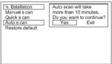
text_image
Installation Manual s can Quick s can Auto s can Restore default Auto scan will take more than 10 minutes. Do you want to continue? Yes ExitRestoring Channels
This restores the all channel settings.
MENU
-
Press ☐ button on the remote control in DTT mode.
-
Select "Installation" on the DTT main menu with ⏻ button and press ⬄ button.
-
The password is required to enter the Installation menu. The initial password is 0000.
-
Select "Restore default" and press OK button. The message "All setting would be lost" appears. Select "Yes" and press OK button.

text_image
In stallation Manual scan Quick scan Auto scan Restore default All setting would be lost. Yes ExitNOTE
- The password will return to the default setting when activating "Restore default".
DIGITAL TERRESTRIAL TELEVISION (DTT) OPERATION (continued)
Channel Selections
There are 4 ways to select the channels: stepping through the channel, selecting by number, selecting from the program/favorite list, and using the Electronic Program Guide (EPG).
Stepping through the Channel
Press CHANNEL UP/DOWN button to switch the next or previous channel on the list. Information banner is displayed every time channel is switched.
Refer to 40 about the information banner.
Selecting from the Program / Favorite List
- Program List
All tuned channel is selectable from Program List.
-
Press ☐ [Yellow] button on the remote control to show up the Program List.
-
Use button to select and press OK button. Then it jumps to the selected channel.
- Favorite List
Your favorite channels can be selected from Favorite List.
-
Press ☐ [Blue] button on the remote control to show up the Favorite list. Each time pressed, it switches to Favorite list 1, Favorite list 2 and off.
-
Use button to select and press OK button. Then it jumps to the selected channel. About how to set the channel in Favorite list, please refer to 39.
| Program list | |
| 06-0007 | 7 Channel 1 |
| 06-0070 | 7 Channel 2 |
| 06-0071 | 7 Channel 3 |
| 06-0072 | 7 Channel A |
| 06-0073 | 7 Channel B |
| 06-0077 | 7 Channel Digital |
| Favorite list 1 | |
| 06-0007 | 7 Channel 1 |
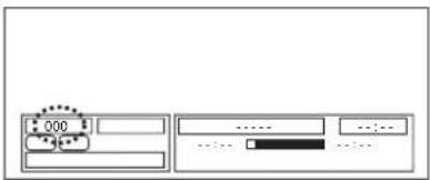
Selecting by Number
Enter the number (the last 4 digits) based on the list by using numeric buttons on the remote control. An empty information banner shows up with the entered number. Channel is switched if the number is valid. If the entered number is not valid for one of the setup channels, it automatically selects the closest channel.
text_image
000 ............Using the Electronic Program Guide (EPG)
The EPG screen displays a list of the stored channel (4 channels per page) along with the now & next program name. You can select a channel from the EPG channel List.
-
Press GUIDE button to access EPG screen.
-
Use ⬆ button to select and press ⏻ button.
-
Press ⏻ button or Ⓔ button again to return to normal screen.

text_image
Electronic Program Guide Tuesday 05:05 AM ●06-0007 7 Channel 1 06-0070 7 Channel 2 06-0071 7 Channel 3 06-0072 7 Channel A Seven Network 7 Channel 1 05:00AM(05:30) IT'S ACADEMIC 7 Channel 1 05:30AM(06:00) SEVEN NEWS AT 4:30 RETURN ●DIGITAL TERRESTRIAL TELEVISION (DTT) OPERATION (continued)
Making Favorite List
The "Edit channels" menu allows you to select your favorite channels and make a Favorite List in order to access easily to the channel you watch most often.
- Press button on the remote control and select "Edit channels" and press OK button.
- Use ⬆ button to select the channel, and ▶ button to select Fav.1 or Fav.2.
- Press OK button to set up as Fav. List. The ♥ mark will show up, which means as favorite channel. Pressing OK button again on the mark will cancel the setting.
You can display favorite list by pressing [Blue] button. (Refer to 38.)
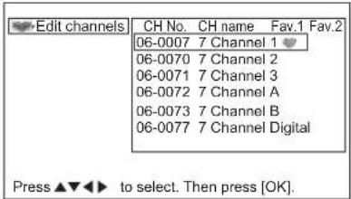
text_image
Edit channels CH No. CH name Fav.1 Fav.2 06-0007 7 Channel 1 06-0070 7 Channel 2 06-0071 7 Channel 3 06-0072 7 Channel A 06-0073 7 Channel B 06-0077 7 Channel Digital Press ▲▼◀▶ to select. Then press [OK].DIGITAL TERRESTRIAL TELEVISION (DTT) OPERATION (continued)
Utilizing the Information Tool
Information Banner
Whenever a channel is switched, the TV displays the picture along with an information banner at the bottom of screen. The information banner also appears by pressing 🕒 button while watching DTT. While displaying information banner, press 🕒 button one more time, the description currently being broadcast shows up. Pressing it again, the description of next program appears.
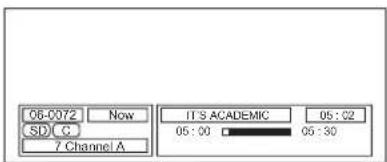
text_image
06-0072 Now IT'S ACADEMIC 05:02 SD C 05:00 05:30 7 Channel A- Set up the display time
The display time of information banner can be set up from 0 to 20 sec.
- Press MENU button on the remote control.
- Select "General settings" and press OK button.
- Select "Option setup" and press OK button.
- The box shows up, and select the display time by using ◀ button.
NOTE
- When you select "0 sec" for "Information box timeout", the information banner will not show up.

text_image
General settings Information box timeout 6 sec Option setup Change pin Local time Subtitle setting Press ◀ to select. Then press [OK].Digital Teletext
Teletext can provide various information with text on the screen.
Press Ⓞ button to access. Press it again to return to the normal screen.
| Operation Press | |
| To activate Teletext mode.To exit from the Teletext mode. | |
| To move to the next or previous page. | |
| To jump to the indicated page. | 0 ~ 9 |
NOTE
See 35 how to operate at Analog teletext.
The service of digital broadcasting signal varies depending on the area.

text_image
P100 Austext 100 Tue 14 Mar 16:04:58 AUSTEXT MAIN INDEX COPYRIGHT INFORMATION ON 104 INDEX INFORMATION MAIN INDEX . 100 GENERAL INDEX. . . . . . . . . . . . . . . . . . . . . . . . . . . . . . . . . . . . . . . . . . . . . . . HUSINESS. . 113 HOROSCOPES. . . . . . . . . . . . . . . . . . . . . . . . . . . . . . . . . . . . . . NEWS. 119 SCI/TECH NEWS. . . . . . . . . . . . . . . . . . . . . . . . . . . . . . . SPORT. 160 SHOWBIZ NEWS. 683 WEATHER. 300 TEST PAGES. 690 TAR SERVICE 500 CAPTIONS. 801 FOR LOCAL NEWS GENERAL INFO 600 TV PROGRAMS 650 CAPTIONS. 801 NATIONAL NEWS INDEX PAGE 120
text_image
1 2 3 4 5 6 7 8 9 0 LIST PAY SICK SHOW — START TIME PHOTODIGITAL TERRESTRIAL TELEVISION (DTT) OPERATION (continued)
Electronic Program Guide (EPG)
The EPG screen displays a list of the stored channels (4 channels per page) along with information the now & next program name.
- Press GUIDE button to display EPG screen.
- Select the desired channel with ⏻ button and press ⏻ button.
- Press 📄 button or 📋 button to return to the normal screen.
text_image
Electronic Program Guide Tuesday 05:05 AM ●06-0007 7 Channel1 06-0070 7 Channel2 06-0071 7 Channel3 06-0072 7 ChannelA Seven Network 7 Channel 1 05:00AM(05:30) IT'S ACADEMIC 7 Channel 1 05:30AM(06:00) SEVEN NEWS AT 4:30 RETURN ⬆NOTE
Not all channels broadcast all program information data. Some channels do not provide program name and details. In that case, only channel name are displayed.
Subtitle
This enables (/ disable) the subtitle if available as your useful tool.
- Press MENU button to display DTT main menu.
- Select "General settings" and press OK button.
-
Select "Subtitle setting" and press OK button.
-
With ⏻ button, select "Enable" and press OK button. You can also activate the subtitle by pressing 🤘 button on the remote control. "Subtitles On" or "Subtitles Off" will appear on the upper left corner.

text_image
General settings Option setup Change pin Local time Subtitle setting Auto subtitle Enable Disable Press ▲▼ to select. Then press [OK].NOTE
- Once turing TV off, "Auto subtitle" returns to "Disable".

text_image
3 subtitles OnDIGITAL TERRESTRIAL TELEVISION (DTT) OPERATION (continued)
Configuring Setting
Parental guidance
Any channel can be locked so that it cannot be selected for viewing without 4 digits pin code.
- Press MENU button on the remote control.
- Select "Parental guidance" and press OK button.
- The password is required to enter. (The initial password is 0000.)
- With ⬆ button, select the rating and press Ⓞ button.
After this protection, when encounter the channel blocked, the message shows up and the password is required to view the channel.

text_image
Parental guidance Child lock No Block Block G and above Block PG and above Block M and above Block MA and above Block AV and above Block R and above Block All
text_image
Parental Guidance Control is activated for this program. Select another channel or enter password to overwrite. Password □ □ □ 06-070 □ Now C 7 Channel 2 IT'S ACADEMIC 05:01 05:00 □ 05:30Audio language
The available Audio language can be selected.
- Press ① button on the remote control in DTT mode.
- The available audio language appears.
- With ⬆ button, select the audio language and press OK button.
text_image
Audio language Language 1 (Mpeg)Change pin
To use the locks effectively, do change the pin number from the default setting, which should be known and remembered only by you. The default setting is 0000.
- Press MENU button on the remote control.
- Select "General setting" and press OK button.
- Select "Change pin" and press OK button.
- The box appears to fill out the old and new password, and the confirmation of the new password.
- Use the numeric number to enter.

text_image
General settings Option setup Change pin Local time Subtitle setting Off password New password Confirm new password * * * * * * * * * * * * * * * *NOTE In case that you forget your password, please refer to Troubleshooting on 53.
Local time
Make sure to select your resident area to set up the correct local time.
- Press MENU button on the remote control.
- Select "General setting" and press OK button.
- Select "Local time" and press OK button.
- Use ⬆ button, select the area and press ⏻ button.
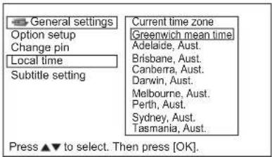
text_image
General settings Option setup Change pin Local time Subtitle setting Current time zone Greenwich mean time Adelaide, Aust. Brisbane, Aust. Canberra, Aust. Darwin, Aust. Melbourne, Aust. Perth, Aust. Sydney, Aust. Tasmania, Aust. Press ▲▼ to select. Then press [OK].DIGITAL TERRESTRIAL TELEVISION (DTT) OPERATION (continued)
Checking DTT System Information
This can display current DTT system information.
- Press MENU button on the remote control.
- Select "System" and press Ⓞ button.
- Pressing OK button on "Status" shows up System information. (H/W version, S/W version, and Release time)
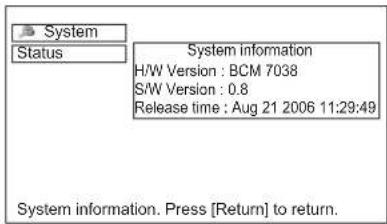
text_image
System Status System information H/W Version : BCM 7038 S/W Version : 0.8 Release time : Aug 21 2006 11:29:49 System information. Press [Return] to return.*The above is an example.
TV Setup Menu
"TV Setup" menu can be accessed from the DTT main menu.
It jumps to the TV main menu containing Analog TV function, such as Picture menu and Audio menu.
Refer to 21 \~ 34 regarding the setting for the details.
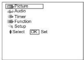
text_image
Picture Audio Timer Function Setup Select OK SetFUNCTION
Size Switching
Each time Ⓗ button of the remote control is pressed, the screen display size is switched in sequence, and the status will be displayed at the bottom of the screen.
TV/AV signal input
ZOOM button
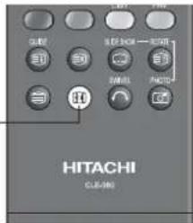
text_image
SUBF LED INCH → OFF SINK PANSS HITACHI CLUB-400- Watching Standard Definition Pictures (480i, 480p, 576i, 576p) DTT/TV/AV1/AV2/AV3/AV4/HDMI1/HDMI2
flowchart
graph LR
    A["4:3 Panoramic1"] --> B["Panoramic2 Zoom"]
    B --> C["CinemaFull"]
    C --> A
- Watching High Definition Pictures (720p, 1080i, 1080p (HDMI only)) AV1/AV2/HDMI1/HDMI2

* During DTT input, the part of OSD might not be displayed in Panoramic mode.
You can display the image at optimum condition by selecting display size depending on the current output image as shown below.
| Input Signal | Display Screen | Display Size | To display suitable screen as follows. |
| When Watching SD Pictures: | |||
 (4:3 Signal) (4:3 Signal) |  | 4:3 | Play a 4:3 image on screen faithfully. Blanking occurs on both sides. |
 | Panoramic1 | Play a 4:3 image which enlarges horizontal and vertical size of the middle in equal scales, and displays both sides appearing much wider. | |
 | Panoramic2 | The vertical size of Panoramic1 is reduced so that you can see the whole image, including any subtitles, that might otherwise not be fully visible on the screen. | |
 (Vista) (Vista) |  | Zoom | Play a 16:9 image in 4:3 frame (Vista size) faithfully.*In some case, slight blanking may remain at the top and bottom. |
 (Cinema) (Cinema) |  | Cinema | Play a 21:9 image in 4:3 frame (Cinema size) expanding vertically.*In some case, slight blanking may remain at the top and bottom. |
 (Squeeze) (Squeeze) |  | Full | Play a 4:3 image faithfully in the standard vertical size and horizontally squeezed. |
| When Watching HD Pictures: | |||
 (16:9 Signal) (16:9 Signal) |  | Full | Play a 16:9 image faithfully showing 95% of the size. |
 | Full 1080 | Play a 16:9 image faithfully showing 100% of the size.*In some case, the screen display has unnecessary blanking or noise at the edges. | |
  |  | Panoramic | Play a 4:3 image in 16:9 frame which enlarges horizontal and vertical size of the middle in equal scales, and displays both sides appearing much wider. |

Information
Aspect ratio represents horizontal : vertical ratio on screen. For example, vista image is 16:9 in 4:3 image.
FUNCTION (continued)
Size Switching (continued)
TV/AV signal input (continued)
- Position Adjustment
Vertical picture position can be adjusted for Panoramic1, Zoom, Cinema, and Full 1080 mode as follows.
- Press ⬆ button while operating the picture size display.
- "Position" display will appear.
- Adjust the position by ⬆ button.
Adjustment range of each picture size are as shown below.
| Display Size | Adjustable Range | Condition/Remark | |
| Panoramic1 | -12 ~ +1 | 2 | |
| Zoom, Cinema | -31 ~ +31 | ||
| Full 1080 | ±1 | Component signal only | |
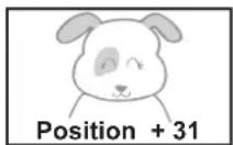
Press ▲

Press ▼
CAUTION
Using a wide-screen television
- This television has a screen mode selection feature. If an incompatible screen mode is selected to play certain software, such as a TV program, the image would appear different from the original. Take this into consideration when making screen mode choices.
- Use of the wide feature displaying enlarged pictures in coffee shops, hotel and other establishments for commercial or public viewing purposes could infringe on the copyright holder's right protected by Copyright Law.
- When a normal 4:3 image (not wide screen) is displayed over the entire screen in the Panoramic mode, the peripheral image may disappear partly and/or appear distorted in some cases. Use 4:3 mode to view the image reflecting original intention.
FUNCTION (continued)
Size Switching (continued)
RGB signal input
You can select suitable size depending on the resolution.

Display Area Selection Diagram
| Resolution | Input signal | Full display | Circular display | |
| Display Full Normal Zoom | ||||
| 640 X 480 (VGA)800 X 600 (SVGA)1024 X 768 (XGA)1280 X 1024 (SXGA) |  |  |  |  |
| 640 X 400 (VGA)1280 X 768 (WXGA) |  |  |  |  |
| 1366 X 768 (WXGA) |  |  | -* | -* |
In the signal display chart shown above, some compression or stretching has taken place. Flicker may be noticeable in Zoom mode depending on content.
* 1366 X 768 (WXGA) is available only in Full mode.
FUNCTION (continued)
Picture Freezing
By pressing ⏻ button, you can change to freeze mode easily anytime you like. Press it again to return to normal picture.
FREEZE button

There are two types of freeze mode. You can select these in the "Freeze Mode" from Function Menu.(26)
Single:
It freezes a picture on a single frame.
Split:
It displays 2 pictures from the same source. One is active (left), while the other is still picture (right). This is very useful in order to avoid missing something or to make a note of something, such as a recipe.


* The size of the pictures differs depending on the signal format received.
NOTE
• This function is not available in RGB input.
FUNCTION (continued)
Audio Switching
NICAM / Sound Multiplex(including A2) (TV mode)
You can make optimum use of available audio by pressing 1/8 button of remote control. Audio can be switched only if receiving NICAM and sound multiplex signals; otherwise, pressing this button will have no effect, such as when only mono sound is received.
These can be divided into two main categories: Bilingual/Dual Sound broadcast and Stereo broadcast.
Bilingual/Dual Sound broadcast
Bilingual broadcast is the broadcast available on the main and sub languages, while dual sound broadcast is available on the primary and secondary sounds; for example, some sports programs contain broadcast commentary on a game as primary sound, and a commentary about a team as the secondary.
When bilingual program is received, sound mode display appears in yellow as shown. Also, when receiving NICAM signals, NICAM display will appear.
Each time ⏻ button is pressed, the display is switched in the sequence of following.
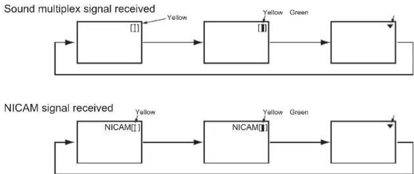
flowchart
graph LR
    A["Sound multiplex signal received"] --> B["[I"]]
    B --> C["Yellow"]
    C --> D["[II"]]
    D --> E["Yellow Green"]
    F["NICAM signal received"] --> G["NICAM[I"]]
    G --> H["Yellow"]
    H --> I["NICAM[II"]]
    I --> J["Yellow Green"]
    J --> K[" "]
[]...Main language/Primary Sound
[1]...Sub language/Secondary Sound
▼...force mono: This selects main language or primary sound.
Stereo broadcast
With stereo broadcast, you can enjoy different sound from either side.
When a stereo program is received, sound mode display will appear in red as shown.
Also, when receiving NICAM signals, NICAM display will appear.
Press / button to switch between stereo and mono sound.
Sound multiplex signal received
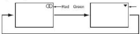
flowchart
graph LR
    A["Block 1"] -->|Red| B["Block 2"]
    B -->|Green| A
NICAM signal received
∅...Stereo
▼.....Force Mono

flowchart
graph LR
    A["NICAM①"] -->|Red| B["Green"]
    B -->|Green| A
NOTE
- Please select ▼ (force mono) in case of poor reception, noise, poor stereo sound due to signal condition so that you can receive a clear mono sound.
• ▽ represents the Mono broadcast.
FUNCTION (continued)
Power Save Mode
When AV input is selected
- You are provided the function to save power consumption when no signal is detected in AV input. Set to On in "Video Power Save" from Function Menu, which leads to the power save mode in AV1 /AV2 /HDMI1 /HDMI2 and the Standby mode in other AV input. (Please see the table below for details) Refer to 26 about "Video Power Save".
| When no signal is detected | When signal is input during On in “Video Power Save” | ||
| Condition Indicating Lamp | |||
| AV1, AV2, HDMI1, HDMI2 | Power Save | Orange | Turns On automatically. |
| AV3, AV4 | Standby | Red | Remains as Standby mode. |
When the RGB input is selected
- When this unit is connected to a VESA DPMS computer, the Power Save mode (Operation mode : Off) can be set to be activated automatically when the computer is not being used to reduce power consumption by this unit.
| RGB sync signal | Horizontal | Yes No Yes No | |||
| Vertical | Yes Yes No No | ||||
| PC signal | Active (normal display) | Blank (no display) | |||
| Operation mode | On | Off | |||
| Indicating lamp | Lights green | Lights orange | |||
Returning to operating status
- Operate the personal computer, or press either the INPUT SELECT button of the control panel or the RGB button of the remote control.
FUNCTION (continued)
DVD Player / STB Selection
You can use this remote control to operate DVD Player and Set Top Box of other makers as well as this set. After pressing ☑ button, press (or hold) the required buttons to select the maker and type as shown below.
Set up
Example: HITACHI DVD②
- Set up the maker.
Press 📄 button to indicate the DVD LED on the remote control. While the DVD LED is blinking (Approx. 30 Seconds), press ⏻ and Ⓐ buttons.
- Set up the maker type.
Release the ① button while keeping ⏻ button depressed. Then press ② button.
- Confirm the setting.
After setting the maker and type, press the SUB POWER button on the remote control. If the DVD does not switch ON, repeat step 1 and 2 using other maker types as listed.

text_image
HITACHI DAJIN<“DVD” Selection>
| Makers of DVD Player | Set Maker | Set type | Makers of DVD Player | Set Maker | Set type |
| HITACHI | 1 | 1~3 | RCA | 0 | 1 |
| FUNAI | 2 | 1 | Mitsubishi | 1 | 1 |
| Pioneer | 3 | 1~6 | ONKYO | RED | 1~3 |
| Panasonic | 4 | 1~4 | ZENITH | GREEN | 1 |
| TOSHIBA | 5 | 1~4 | THOMSON | YELLOW | 1 |
| Philips | 6 | 1~2 | SHINCO | BLUE | 1 |
| JVC | 7 | 1 | SKYWORTH | E | 1 |
| SAMSUNG | 8 | 1 | BUBUKO | E | 1 |
| Sony | 9 | 1~4 | DENON | C | 1~2 |
| Sharp | 10 | 1~2 | YAMAHA | S | 1~2 |
<“STB” Selection>
| Makers of STB Player | Set Maker | Set type |
| HITACHI | ||
| TOSHIBA | ||
| DGTEC | ||
| Panasonic |
NOTE
Please note that not all models of the listed makers can be operated using this remote control.
TROUBLESHOOTING
Before calling service technician, check the following tables first. If the problem is not be solved with the suggested procedures, contact your local dealer. For your safety, NEVER try to repair the product by yourself.
When Following Messages Appear on the Screen
| Message Condition / | Action Page | |
| Power Save | This indicates it is in Power Save mode. (in AV/RGB mode)The indicating lamp lights in orange. | 26, 49 |
| No Sync. Signal | The unit cannot detect any signals from any input terminals.Check if the cable is connected correctly and firmly.Check if the power of any external equipment is ON.Check if the input selection matches the connection terminal.Check if the PC is in Power Save mode or not. | 14 ~ 16 |
| Invalid Scan Freq. | The unit receives unsupported signals.Check if the cable is connected correctly and firmly.Check if the input signal is compatible with the specification of the television. | 54, 56 |
| Not Available | This shows when the selected operation is not available. | |
| Please Push [Return] button | This message appears when you select other than 🎨 button while Screen Wipe is ON.Press 🔺 button when this message appears. | 26 |
| Check Antenna | Check the connection status when this message appears. | 13 |
| Auto Adjusting | This indicates that it is in the process of auto adjusting. (in RGB mode) | 25 |
| Weak signal | Check aerial lead if it is disconnected/damaged/misaligned. (in DTT mode)Check with your dealer if it is out of signal area or not. (in DTT mode) | |
| Bad or No signal |
Symptom and Check List
| Symptoms Check list | Page | ||
| No picture - no sound | Check the Indicating lamp status (Off, Red, Green, or Orange).Check the connection of the Power Cord and/or other cables.Check if the Main Power of the unit or external equipments is ON.Check if the TV mode is selected.Check if the TV is in "Standby mode" or "Power Save mode".Adjust the values in "Picture menu" and "Audio menu". | 13 ~ 1820 49 | |
| Snowy picture-poor sound |  | Check the antenna connection and direction.The TV station may have broadcast difficulties.Try another channel. | 13 |
| Multiple images-normal sound |  | Check the antenna connection and direction.Fine tuning the TV.Check the connection of the external equipments.The TV station may have broadcast difficulties.Try another channel. | 13 23 |
| Intermittent interference |  | Check if the source of interference is shielded well.Remove those kinds of electrical devices away from the TV. | |
| Normal picture, but no sound | Check the volume level.Check if the button has been pressed or not.Make sure that the headphone is NOT connected.Check the connection of the external equipments. | 19 | |
| No picture - normal sound | Check the value level of "Brightness" and "Contrast" in "Picture Menu". | 28 31 | |
| The remote control does not work. | Check if the batteries are installed correctly.The batteries might be exhausted. Replace them with new ones.Remove all the obstructions in front of the sensor window on the unit.Check if you select the correct function by button on the remote control.Check if the buttons of the control panel can work. | 10 11 | |
| Normal picture but no color-normal sound | Check the connection of the external equipments.Check the "Sound System" and "Color System" in "Setup Menu". | 14 ~ 1622 ~ 24 |
TROUBLESHOOTING (continued)
Symptom and Check List (continued)
| Symptoms Check list Page | ||
| • Image is paused. | • Check if the TV is in freeze mode by pressing 📋 button. | 47 |
| • No pictureThe Indicating lamp → Off | • Check if the Power Cord is plugged into the socket firmly.• Check if the Main Power is ON. | 17, 18 |
| • No pictureThe Indicating lamp → OrangeIt means that the unit is in “Power Save mode”. | • Check if all the cables of the external equipments are connected correctly and firmly.• Check if the power of the external equipments is ON.• Check if the TV/AV mode has been selected correctly.• Check if the PC is in Power Save mode or not.• Refer to “Power Save mode” and “When following messages appears on the screen”. | 49, 51 |
| • No pictureThe indicating lamp → Green | • Check if the signal cable is connected correctly and firmly.• Adjust the level of Brightness and Contrast lower. | 14 ~ 16 |
| • The rear of the TV makes a buzzing sound. | • This could be the sound produced by the motor fan when it rotates.This is not a malfunction. | |
| • The top of the unit and surface of the panel heat up. | • It may happen when you use the unit for long hours. Turn off the Main Power of the unit for a while. Please note that this is not malfunction. | 54 |
| • Image cannot be displayed in the correct position. | • Press 📋 button to check if the input signal of the displayed image is compatible with the specification of the television. | 25, 54, 56 |
| • When the VCR is in special playback features (Fast Forward or Rewind), the screen gets dark and cannot see the image at all. | • It could happen when the VCR is connected to Component output, such as 480i. This is not malfunction.• Try Composite output or S-video output and check the picture again. | |
| • Some screen display size cannot be switched. | • Check the signal status by pressing the 📋 button on the remote control. The available screen display size is different depending on the current signal status. | 20, 44 ~ 46 |
| • Cannot be displayed the image from HDMI 1 or 2. | • Check if the cables are connected correctly.• Check the output format of the equipments.(Please refer to “Connecting Procedure” and “Recommended Signal List”). | 54 ~ 56 |
| • The image and audio are mismatched when in RGB or HDMI1/2 mode. | • Check if the PC (RGB)/HDMI analog audio input terminal is connected to the same external device. | 15 |
TROUBLESHOOTING (continued)
Symptom and Check List (continued)
| Symptoms Check list | Page | ||
| The image on the screen is moving in an oblique direction.(PC input mode only) |  | Adjust "Horizontal Clock" and "Clock Phase". | 25 |
| The coarse horizontal stripes could be seen in full-display mode.(PC input mode only) |  | Adjust "Horizontal Clock". | 25 |
| The part of the image is lacking.(PC input mode only) |  | Check if the "Screen Saver" is OFF.Try "Auto Adjust". | 25 26 |
| The horizontal stripes are moving vertically with flickering screen.(PC input mode only) |  | Check the Signal status of the PC by pressing button on the remote control. | |
| When the characters are displayed on the whole screen, the vertical stripes appear and some of the characters are blurred.(PC input mode only) | 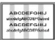 | Try "Auto Adjust".If the display condition is not improved with Auto Adjust, adjust "Horizontal Clock". | 25 |
| When the letter string is displayed in full-screen, all of the characters on the screen are blurred.(PC input mode only) |  | Try "Auto Adjust".If the condition is not improved with Auto Adjust, adjust "Clock Phase" till you get clearest image. | 25 |
| When the small patterns are displayed on the screen, the entire screen is flickering.(PC input mode only) |  | Try "Auto Adjust".If the condition is not improved with Auto Adjust, adjust "Clock Phase" till you get flicker-free display. | 25 |
| The thickness of the letters, lines, etc is not displayed evenly.(PC input mode only) | It could happen when the image with more than 540 lines of vertical resolution is displayed.Please note this is not malfunction. | 56 | |
| No Picture or sound is output.(DTT mode only) | It might occur because it is tuned to digital teletext channel.Return to another channel. | 40 | |
| Forgotten password.(DTT mode only) | Press and hold down [Red], [Green], andbuttons on the remote control simultaneously for over 3 seconds so that the password returns to the default setting (0000). Please note that all tuned channels and adjusted data for both analog and digital will be lost. | 42 | |
| Due to the bad reception, block noise interferes during DTT mode.(DTT mode only) | Check the aerial system to improve signal quality. | 13 | |
| Local time displays incorrectly.(DTT mode only) | Check if you select correct area in "Local time" from "General setting". | 42 |
PRODUCT SPECIFICATIONS
| SPECIFICATION | ||
| Panel | Display dimensions App | rox. 50 inches (1106 (H) x 626 (V) mm, diagonal 1270mm) |
| Resolution 1280 (H) x 1080 (V) pixels | ||
| Net dimensions | including Optional Stand: 1240 (W) x 900 (H) x 423 (D) mmexcluding Optional Stand: 1240 (W) x 836 (H) x 125 (D) mm | |
| Net weight | including Optional Stand: 46.5kgexcluding Optional Stand: 40.7kg | |
| Ambient conditions | Temperature Operating | 5°C to 35°C, Storage: 0°C to 40°C |
| Relative humidity Operating | 20% to 80%, Storage: 20% to 90% (non-condensing) | |
| Power supply | AC240V, 50Hz | |
| Power consumption/ at standby | 480W / <1W | |
| Audio output speaker total 20W | ||
| (VIDEO input) | ||
| Input terminals | AV1•2: composite video input terminal (RCA)component video input terminal (RCA)L/R audio input terminal (RCA)AV3•4: composite video input terminal (RCA)S video input terminal.L/R audio input terminal (RCA)HDMI 1•2 : HDMI input terminalAudio input terminal (L/R audio input terminal (RCA))* | |
| Input signals | Composite video: PAL, SECAM, NTSC3.58, NTSC4.43, PAL60Component video: 480i, 576i, 480p, 576p, 720p/50, 720p/60, 1080i/50, 1080i/60HDMI: VGA/60, 480i, 576i, 480p, 576p, 720p/50, 720p/60, 1080i/50, 1080i/60, 1080p/50, 1080p/60 | |
| Output Signal | OUTPUT (MONITOR): composite video monitor-output terminal (RCA)OUTPUT (MONITOR): L/R audio monitor- output terminal (RCA)OUTPUT (HEADPHONE): L/R audio monitor- output terminal (Mini-pin)OUTPUT (SUB-WOOFER): Woofer output terminal (RCA) | |
| (RF input) | ||
| Input terminal / Receiving range ANT: 75Ω | Unbalanced / 44~870MHz | |
| RF Video System | PAL B, G, H / I / D, KSECAM B, G / D, K / K1NTSC-MDVB-T | |
| (RGB input) | ||
| Input terminals | Analog RGB input terminal (D-sub 15-pin)Audio input terminal (L/R audio input terminal (RCA))* | |
| Input signals 0.7 Vp-p, analog RGB (Recommended Signal) | ||
| Sync signals H/V separate, TTL level [2KΩ] | ||
• The unit takes at least 30 minutes to attain the status of optimal picture quality.
* This analog audio input terminal can be used for PC (RGB) or HDMI1/2 only.
PRODUCT SPECIFICATIONS (continued)
Signal Input
RGB terminal (D-sub 15-pin connector)
| Pin | Input signal |
| 1 | R |
| 2 | G |
| 3 | B |
| 4 | No connection |
| 5 | No connection |
| 6 | R.GND |
| 7 | G.GND |
| 8 | B.GND |
| 9 | No connection |
| 10 | GND |
| 11 | No connection |
| 12 | [SDA] |
| 13 | H.sync |
| 14 | V.sync. [V.CLK] |
| 15 | [SCL] |

text_image
⑤④③②① ⑩⑨⑧⑦⑥ ⑮⑭⑬⑫⑬⑰S-input connector pin specifications
| Pin | Input signal |
| 1 | Y |
| 2 | Y-GND |
| 3 | C |
| 4 | C-GND |
| Frame | GND |

text_image
③ ① ④ ②HDMI connector pin specifications
| Pin | Input signal | Pin | Input signal | |
| 1 | TMDS Data2+ | 11 | TMDS Clock | Shield |
| 2 | TMDS Data2 Shield | 12 | ||
| 3 | TMDS Data2- | 13 CEC | ||
| 4 | TMDS Data 1+ | 14 | ||
| 5 | TMDS Data1 Shield | 15 | ||
| 6 | TMDS Data1- | 16 | ||
| 7 | TMDS Data0+ | 17 | DDC/CEC Ground | |
| 8 | TMDS Data0 Shield | 18 | ||
| 9 | TMDS Data0- | 19 Hot Plug Detect | ||
| 10 | TMDS Clock+ | |||
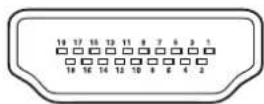
PRODUCT SPECIFICATIONS (continued)
Recommended Signal List
With HDMI input
| No. | Signal mode | Horizontal frequency (kHz) | Dot clock frequency (MHz) | Remarks | |||||
| Signal Name | Resolution | Vertical frequency (Hz) | |||||||
| 1 | VGA 640 X | 480 | 59.94 | 31.47 | 25.18 | EIA/CEA-861B | |||
| 2 | 576i | 720(1440) X 576 | 50.00 | 15.63 | 27.00 | EIA/CEA-861B | |||
| 3 | 480i | 720(1440) X 480 | 59.94 | 15.73 | 27.00 | EIA/CEA-861B | |||
| 4 | 576p 720 X | 576 | 50.00 | 31.25 | 27.00 | EIA/CEA-861B | |||
| 5 | 480p 720 X | 480 | 59.94 | 31.47 | 27.00 | EIA/CEA-861B | |||
| 6 | 1080i/50 1920 X 1080 50.00 | 28.13 | 74.25 | EIA/CEA-861B | |||||
| 7 | 1080i/60 1920 X 1080 60.00 | 33.75 | 74.25 | EIA/CEA-861B | |||||
| 8 | 720p/50 | 1280 X 720 | 50.00 | 37.50 | 74.25 | EIA/CEA-861B | |||
| 9 | 720p/60 | 1280 X 720 | 60.00 | 45.00 | 74.25 | EIA/CEA-861B | |||
| 10 | 1080p/50 | 1920 X 1080 | 50.00 | 56.25 | 148.50 | EIA/CEA-861B | |||
| 11 | 1080p/60 | 1920 X 1080 | 60.00 | 67.50 | 148.50 | EIA/CEA-861B | |||
With RGB input
| No. | Signal mode | Horizontal frequency (kHz) | Dot clock frequency (MHz) | Remarks | ||||
| Signal Name | Resolution | Vertical frequency (Hz) | ||||||
| 1 | VGA | 640 X 400 | 70.08 | 31.47 | 25.18 | |||
| 2 | 640 X 480 | 59.94 | 31.47 | 25.18 | ||||
| 3 | VESA | 800 X 600 | 60.32 | 37.88 | 40.00 | |||
| 4 | 1024 X 768 | 60.00 | 48.36 | 65.00 | ||||
| 5 | 1280 X 1024 | 60.02 | 63.98 | 108.00 | ||||
| 6 | W-XGA | 1280 X 768 | 59.876 | 47.776 | 79.50 | WXGA Mode : 1280x768 | ||
| 7 | 1366 X 768 | 60.015 | 47.712 | 85.50 | WXGA Mode : 1366x768 | |||
- The type of video board or connecting cable used may not allow for correct displays adjustment of Horizontal Position, Vertical Position, Horizontal Clock and Clock Phase.
- The unit differentiates the signal modes according to the horizontal and vertical frequencies and the horizontal and vertical sync signal polarities. Note that different signals having all these elements alike may be handled as the same signal.
- Displaying images with more than 540 lines of vertical resolution at Full display (compressed display) can result in the interpolation of stripes.