
IG-641RPOE - Kytkin AIRLIVE - Ilmainen käyttöohje ja opas
Löydä laitteen käyttöohje ilmaiseksi IG-641RPOE AIRLIVE PDF-muodossa.

Käyttäjien kysymyksiä aiheesta IG-641RPOE AIRLIVE
0 kysymys tästä laitteesta. Vastaa tuntemiisi tai esitä omasi.
Esitä uusi kysymys tästä laitteesta
Lataa ohjeet laitteellesi Kytkin PDF-muodossa ilmaiseksi! Löydä käyttöohjeesi IG-641RPOE - AIRLIVE ja ota elektroninen laitteesi takaisin hallintaan. Tällä sivulla julkaistaan kaikki laitteidesi käyttöön tarvittavat asiakirjat. IG-641RPOE merkiltä AIRLIVE.
KÄYTTÖOHJE IG-641RPOE AIRLIVE
www.airlive.com
Quick Setup Guide

Declaration of Conformity
We, Manufacturer/Importer
AirLive Technology Corporation
4F, No.132, Lane 235, Baoqian Rd., Xindian Dist.,
New Taipei City 23145, Taiwan
Declare that the product
Industrial Unmanaged PoE Switch
IG-641RPOE
is in conformity with
In accordance with 2014/30/EU and 2014/35/EU Directive
Clause
■ EN 55032:2015
Description
Electromagnetic compatibility (EMC)
■ EN 62368-1
Electromagnetic compatibility (LVD)
■ CE marking

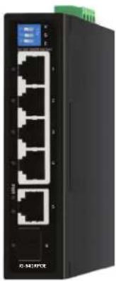
natural_image
Front view of a black wireless network switch device with multiple Ethernet ports and a digital display (no visible text or symbols on the device body)Manufacturer/Importer
Name : A van Rossem Position/ Title : Product Manager
Date : May 2024Place : Republic of China (Taiwan)
Regulatory Approvals
- CE Statement
This product complies with the 2014/30/EU and 2014/35/EU directives, including the following safety and EMC standards:
■ EN 55032:2015+A11:2020
Electromagnetic compatibility (EMC)
■ EN IEC 61000-3-2:2019
Electromagnetic compatibility (EMC)
■ EN 61000-3-3:2013+A1:2019
Electromagnetic compatibility (EMC)
■ EN 55035:2017+A11:2020
Electromagnetic compatibility (EMC)
■ EN 62368-1:2014+A11:2017
Electromagnetic compatibility (LVD) - Safety
• RoHS Statement
This product complies with RoHS directive 2011/65/EU and amendment Commission Delegated Directive (EU)2015/863.
■IEC 62321-3-1:2013
■IEC 62321-5:2013
■IEC 62321-4:2013+AMD1:2017
■IEC 62321-7-1:2015
■IEC 62321-7-2:2017
■IEC 62321-6:2015
■IEC 62321-8:2017
- CE Marking Warning
This is a Class A product. In a domestic environment this product may cause radio interference in which case the user may be required to take adequate measures.

AirLive Technology Corporation declares that this device is in compliance with the essential requirements and other relevant provisions of directive 2014/30/EU.
www.airlive.com
Quick Setup Guide

Mounting the Switch
The images can differ from the real product, images for guide purpose only.
A. Din-Rail
- Screw the DIN-Rail bracket on with the bracket and screws in the accessory kit.
- Hook the unit over the DIN rail.
- Push the bottom of the unit towards the DIN Rail until it snaps into place.
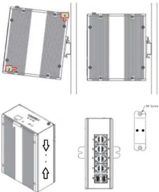
natural_image
Technical line drawings of an electronic device showing front, side, and top views with no visible text or symbolsB. Wall Mount
- Un-Screw the DIN Rail bracket from the Switch and attached the wall-mounting plate on the same location with the plate and screws in the accessory kit.
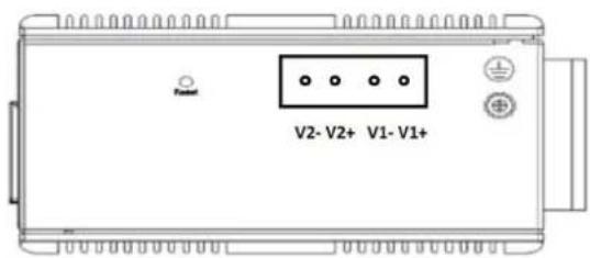
C. Power Connection
- The DC power interface is a 4-pin terminal block with polarity signs on the top panel.
- The Switch can be powered from two power supply (input range 48V\~55V). The DC power connector is a 4-pin terminal block.
*** Installation images for illustration purpose only
LED DEFINITIONS
| Power | ON | Power is on and normal. |
| OFF | The switch is not receiving power. | |
| Link/Act | Green ON | Link Normal. |
| Green OFF | Link Off. | |
| Green Blinking | Link Data Transmitting. |
DIP Switch Control
| V: VLAN Mode | Port isolation mode. In this mode ports 1~4 cannot communicate with each other and can only communicate with the Uplink ports. |
| G: Default Mode | Normal mode. All ports can communicate with each other. |
| E: Extend Mode | Extension mode. PoE power supply and data transmission distance can be extended to 250meter at the transmission rate of 10Mbps Port 1~4 only. |
Merkki : AIRLIVE
Malli : IG-641RPOE
Kategoria : Kytkin