LCT017 - Õhupuhasti Prima - Tasuta kasutusjuhend
Leidke seadme juhend tasuta LCT017 Prima PDF-formaadis.

Kasutajate küsimused teemal LCT017 Prima
0 küsimus selle seadme kohta. Vastake nendele, mida teate, või esitage oma.
Esita uus küsimus selle seadme kohta
Laadige alla juhend oma Õhupuhasti PDF-formaadis tasuta! Leidke oma juhend LCT017 - Prima ja võtke oma elektrooniline seade uuesti kätte. Sellel lehel on avaldatud kõik teie seadme kasutamiseks vajalikud dokumendid. LCT017 kaubamärgi Prima.
KASUTUSJUHEND LCT017 Prima
natural_image
Simple line drawing of a conical structure with a vertical top and base, resembling a stylized lamp or chimney (no text or symbols)Manual for the installation, use and maintenance of decorative hoods
natural_image
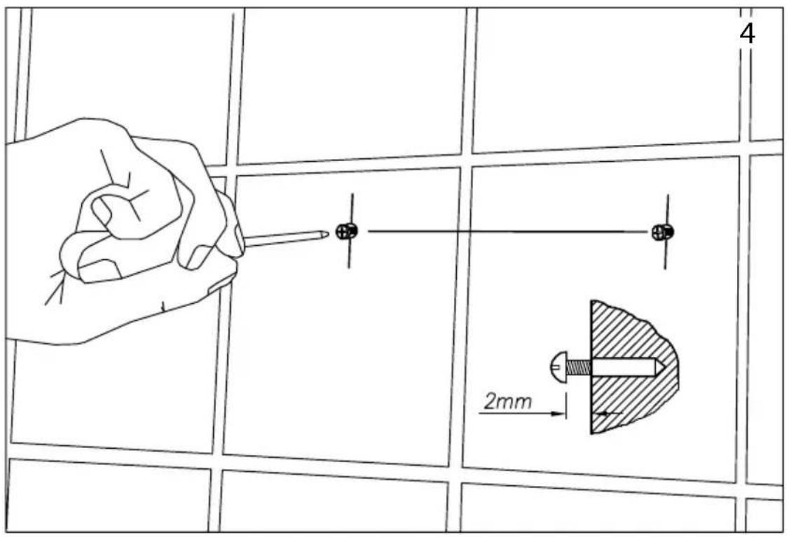
Line drawing of a hand using a tool to clean or inspect a small object on a tiled wall (no text or symbols)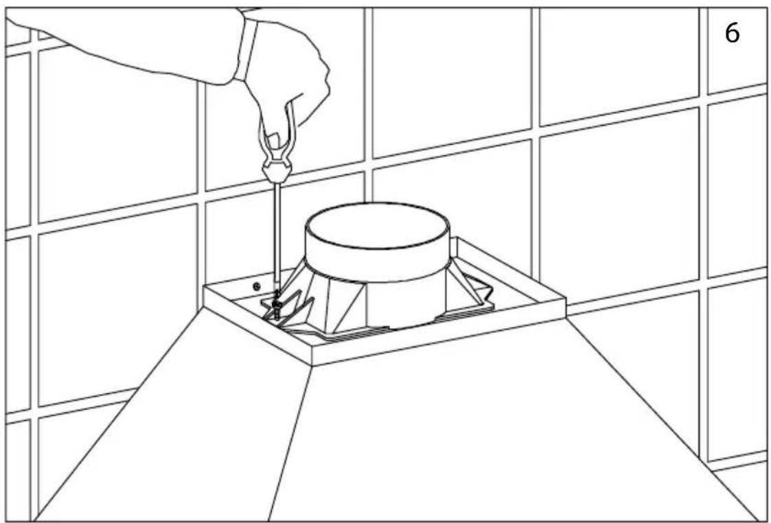
natural_image
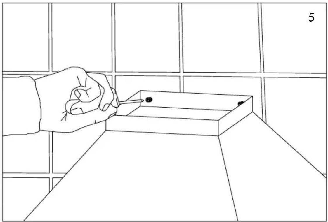
Line drawing of a hand using a tool to install a cylindrical component on a tiled floor, with no text or symbols present.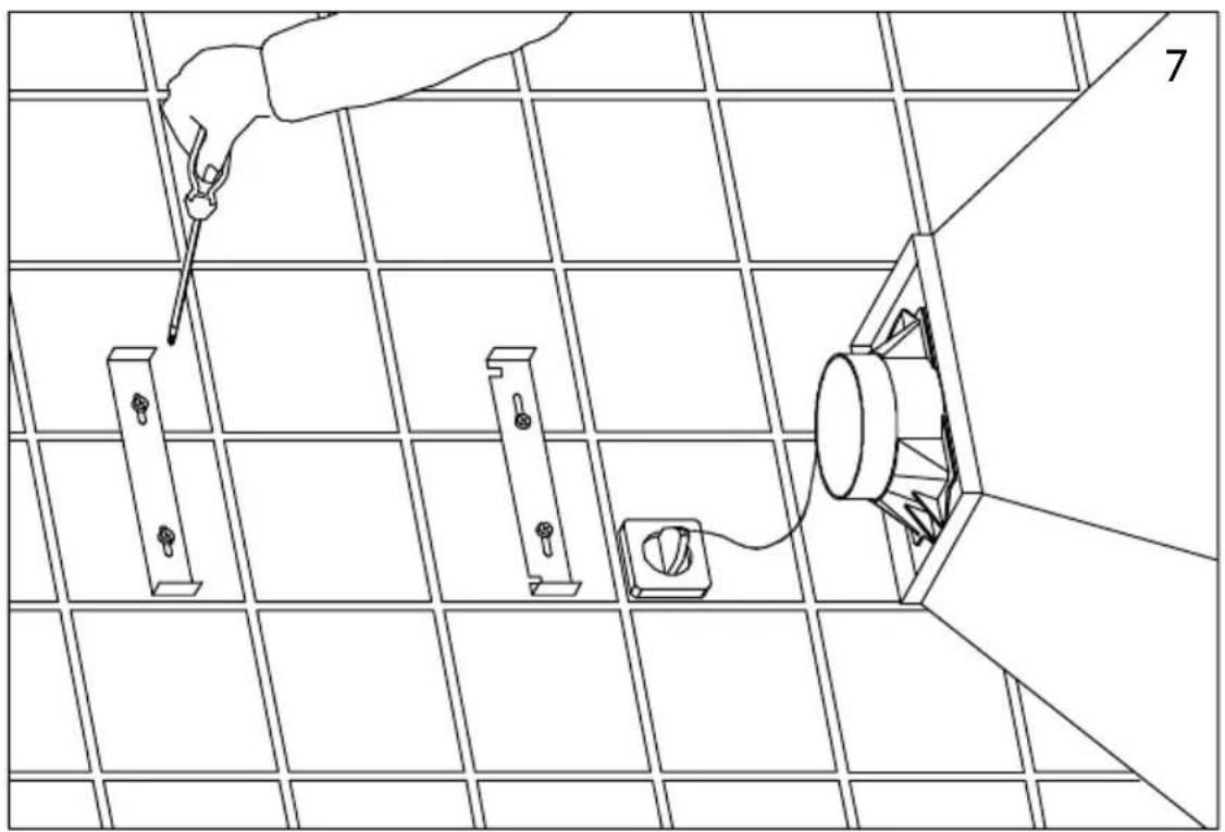
natural_image
Line drawing of a person using a tool to install or install a component on a grid-patterned panel (no text or symbols)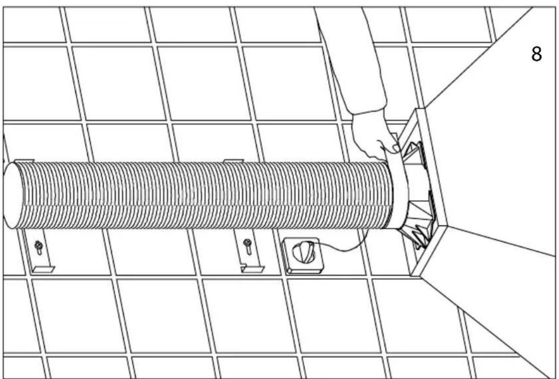
natural_image
Line drawing of a person operating a large cylindrical device mounted on a grid-patterned panel (no text or symbols)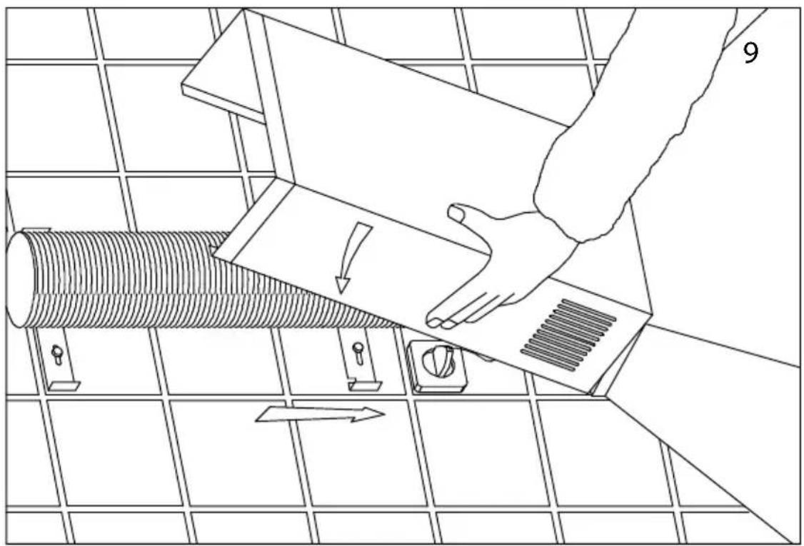
natural_image
Line drawing of a hand using a tool to cut a corrugated metal component on a tiled floor (no text or symbols)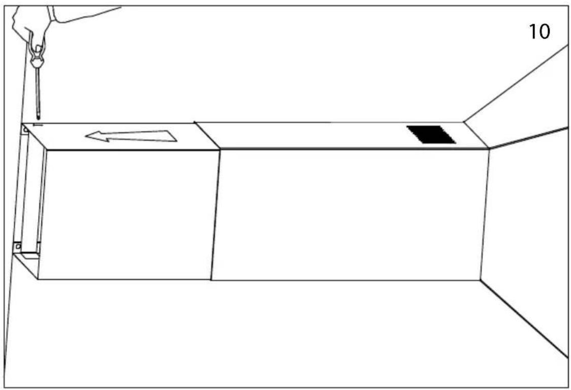
natural_image
Line drawing of a 3D rectangular box with a hand holding a tool, showing an arrow and a small dark square on the side (no text or symbols)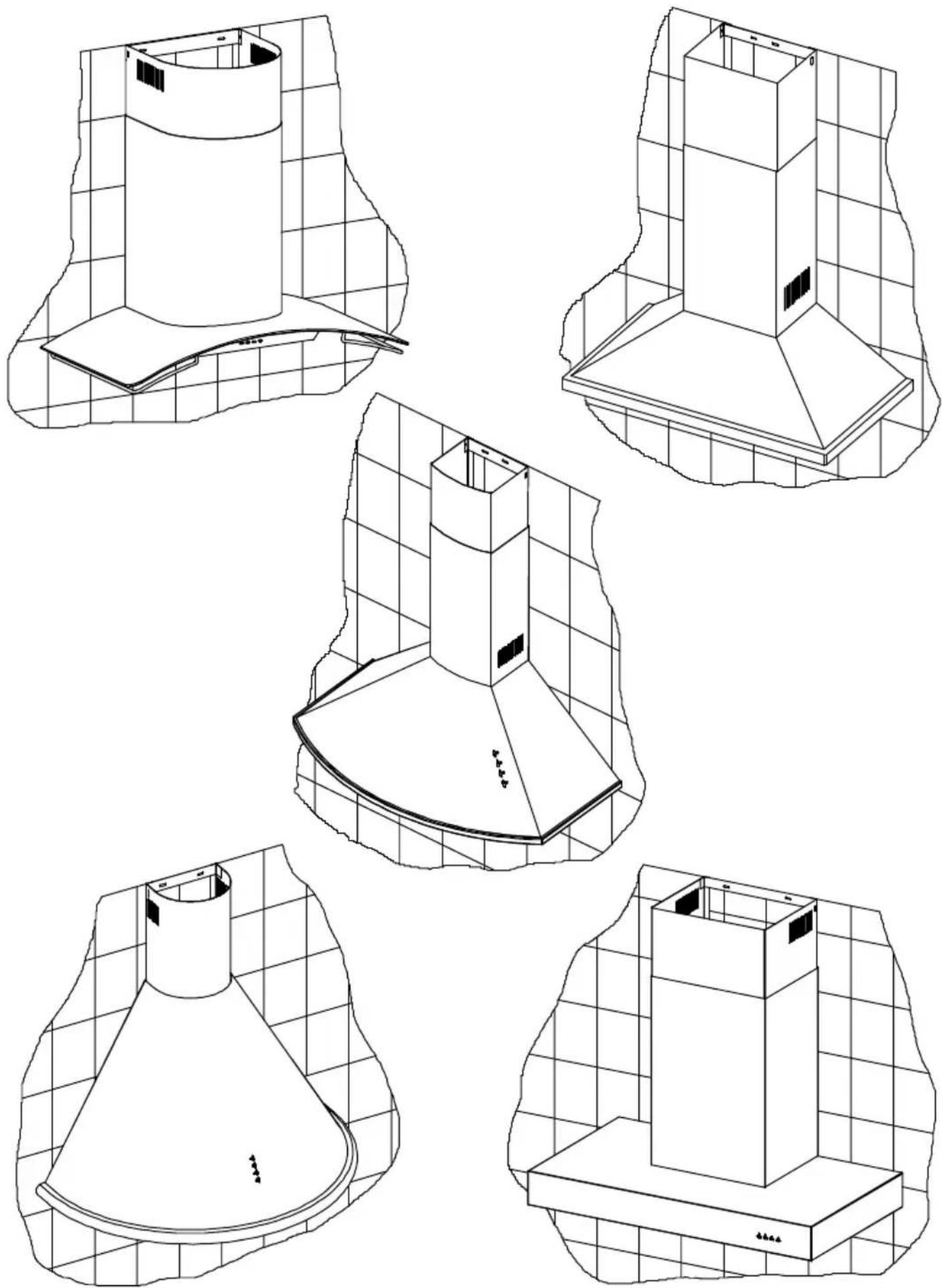
DECORATIVE EXTRACTOR HOODS
Dear client.
We are sure that the purchase of our extractor hood will fully satisfy all of your needs.
Please read this instruction manual carefully in order to obtain the best results from the use of the hood.
INSTRUCTIONS FOR INSTALLATION, MAINTENANCE AND USE
General indications
Before installing and using the hood, be sure that the voltage (V) and the frequency (Hz) indicated on the feature plate match the voltage and frequency at the installation site.
The feature plate and technical data are shown on the inside of the product.
For better performance in extracting fumes we advise that tubing installed should be of a diameter not less than 120 mm. We also advise using rigid PVC tubing.
ELECTRICAL CONNECTION
Connect the cord to a socket or double pole switch, which must have a minimum contact opening distance of 3 mm.
The manufacturer shall not be liable for failure to observe all safety regulations in force for the correct and normal operation of electrical parts.
This hood complies with European Directives EMC No. 89/336 EEC on protection against radial interference.
CONTROL PANELS:
All of the figures of the control panels can be found on the penultimate page.
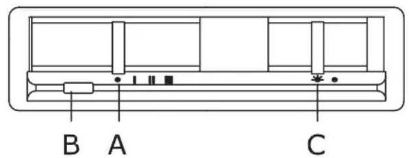
Slider control panel
This panel is located on the lower part of the hood and includes:
- 4 position motor control switch (OFF, 1 ^st , 2 ^nd and 3 ^rd speed positions) (Ref. A).
- Motor control light (Ref. B).
- Light switch (Ref. C).
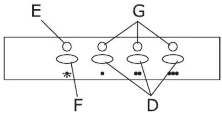
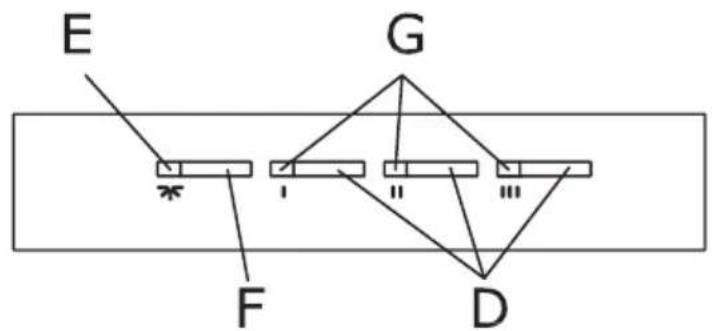
Electronic switch control panel
This panel is located on the front part of the hood and includes:
- 3 position motor control switch (1st, 2nd, and 3rd speed) (Ref. D).
- Lighting control lamp. Fig. 6. (Ref. E).
- Motor control lights. (Ref. G).
- Light switch (Ref. F).
TIMING: To operate the canopy timer, having selected the speed, press the button for two seconds until the LED light blinks. The timer will then work for 15 minutes.
At the end of this time, the motor will stop and the light will go out. If it is still on, and you wish to cancel the timing, press the timer button once and the motor will stop.
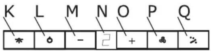
Four-speed control panel with digital indicator
This panel is situated on the front of the extractor and includes:
- Button for the light (ref. K).
- On/off button of the motor (ref. L).
- Button for reducing the motor speed (ref. M).
- Motor speed indicator (ref. N).
- Button for increasing the motor speed (ref. O).
- Button for directly activating the TURBO speed of the motor (ref. P).
- Button for setting the timer of the motor (ref. Q).
The extractor will operate for 5 minutes at the current speed and 5 minutes at each of the lower speeds until coming to a complete stop.
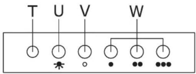
Five-button control panel
This panel is situated on the front of the extractor and includes:
- 3 control switches for the motor (speed positions 1, 2 and 3) (ref W)
- Off button of the motor (ref V)
- On/off light of the motor (ref T)
- Light switch (ref. U)
Mechanical push Four-button control panel:
This panel is located on the front part of the hood and includes:
- 3 position motor control switch (1st, 2nd, and 3rd speed) (Ref. H).
- Motor control light (Ref. I).
- Light switch (Ref. J).
NOTE: To operate at the 2nd and 3rd speeds, the first speed must be activated.
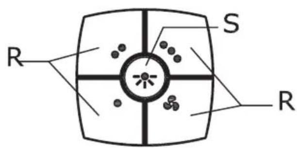
Four-speed control panel
This panel is situated on the front of the extractor and includes:
- 4 buttons for controlling the operation of the motor (position 1, 2, 3 and turbo) (Ref R)
- Button for the light.
MAINTENANCE
-Cleaning
Before any type of operation, always make sure that the electrical cord is disconnected and the switch is in the off position. Clean the external part with a mild, liquid detergent and avoid the use of abrasive cleaning products.
-Changing the light
Before changing the light make sure that the hood is not connected.
Remove the grease filter and replace the light with a light bulb no more powerful than that specified in the Technical Characteristics. Place the filter in position.
-Cleaning the grease filter.
Depending on use, and at least once a month the grease filters should be disassembled and cleaned in a dishwasher or with hot soapy water.
If washed in a dishwasher, the filters should be placed in an upright position to prevent food remains from falling on them.
After rinsing and drying, replace the filters by following the steps for disassembly in reverse order.
The active carbon filters must be replaced periodically to work properly, at least once every three months (depending on the frequency with which the hood is used).
IMPORTANT:
- Do not connect the hood to chimneys, ventilation pipes or hot air pipes. Before connecting any pipes, consult municipal ordinances on exhaust air and request permission from the person in charge of the building. Be sure there is adequate ventilation, even in cases where the hood is to be used simultaneously with another product.
- Never leave frying food unattended since grease can overheat and catch fire. The risk of fire is even greater in the case of used oil.
- Never use the hood in areas where devices with exhaust pipes connected to the outside are already operating unless perfect ventilation can be guaranteed.
- To avoid the possibility of fire, adhere strictly to all of the recommendations included here and to the periodic cleaning of the grease filters.
- During an electrostatic discharge (ESD) it is possible that the device will stop working. By switching the device OFF an ON the device will again work as intended. There is no risk and no risk will appear.
- During climatic conditions causing electrical interference, it is possible that the device may stop working. By switching the device OFF an ON the device will resume normal operation safety.
- If the supply cord of this equipment is damaged, it must only be replaced by manufacturer or its service agent or similarly qualified person in order to avoid a hazard.
- Never have a lighted flame under the extractor hood.
• The appliance must be placed in such a way, that the supply plug is accessible.
• The hood must be installed at a minimum distance of 65cm from the stovetop.
IMPORTANT WARNING FOR EXTRACTOR HOODS WITH HALOGEN LAMPS
If the halogen lamps need replacing, they must be replaced by lamps with an aluminium reflector, never dichroic lamps, to avoid unnecessary overheating in the lamp holders.
THE MANUFACTURER WAIVES ALL LIABILITY FOR FAILURE TO OBSERVE THE INSTRUCTIONS FOR THE APPROPRIATE INSTALLATION, MAINTENANCE AND USE OF THE EXTRACTOR HOOD.
The symbol 📄 on the product or on its packaging indicates that this product may not be treated as household waste. Instead it shall be handed over to the applicable collection point for the recycling of electrical and electronic equipment. By ensuring this product is disposed of correctly, you will help prevent potential negative consequences for the environment and human health, which could otherwise be caused by inappropriate waste handling of this product. For more detailed information about recycling of this product, please contact your local city office, your household waste disposal service or the shop where you purchased the product.
If you need any technical help or would like more information about our products, please do not hesitate to contact our official distributor.
THE MANUFACTURER reserves the right to effect any technological improvement or modification without prior notice.
flowchart
graph TD
    E --> F
    F --> G
    G --> D
    F --> D
    D --> G
    G --> F
    F --> G
    G --> F
    F --> G
    G --> F
    F --> D
    G --> D
    F --> D
    G --> D
    F --> D
    G --> D
    F --> D
    G --> D
    F --> D
    G --> D
    F --> D
    G --> D
    F --> D
    G --> D
    F --> D
    G --> D
    F --> D
    G --> D
    F --> D
    G --> D
    F --> D
    G -->D
Customer Service Number: +0844 8001128
Ver 0711