L110A - Kõlar JBL - Tasuta kasutusjuhend
Leidke seadme juhend tasuta L110A JBL PDF-formaadis.

Kasutajate küsimused teemal L110A JBL
0 küsimus selle seadme kohta. Vastake nendele, mida teate, või esitage oma.
Esita uus küsimus selle seadme kohta
Laadige alla juhend oma Kõlar PDF-formaadis tasuta! Leidke oma juhend L110A - JBL ja võtke oma elektrooniline seade uuesti kätte. Sellel lehel on avaldatud kõik teie seadme kasutamiseks vajalikud dokumendid. L110A kaubamärgi JBL.
KASUTUSJUHEND L110A JBL
L110A
L110 INSTRUCTION MANUAL
natural_image
Black and white abstract pattern with a dark rectangular shape and faint vertical streaks, no text or symbols present.CONTENTS
The L110
Connecting the L110
Placement
Adjusting the System
Power Capacity
Enclosure
Components
Service
Component Removal
For Additional Information
Specifications
1
1
2
3
4
5
31
56
。
(五)
[Non-Text]
s
natural_image
Black-and-white photo of a vintage computer monitor with a face and screen, no visible text or symbolsTHE L110
The L110 incorporates the latest advances in bookshelf loudspeaker system design, offering performance characteristics that rival those of the most sophisticated full-sized JBL loudspeaker systems. Each component was designed for the most extended power-flat frequency response, widest dispersion, bandwidth, and high efficiency. The result is a bookshelf system of exceptional accuracy that re-creates the spaciousness of a live performance. The L110 provides studio quality reproduction in a compact form that affords the flexibility of placement needed in the home.
CONNECTING THE L110
To connect loudspeaker systems placed up to 15 m (50 ft) from the amplifier, 1 mm (#18 AWG) insulated wire (ordinary household lamp cord) is the minimum size recommended. For greater distances, heavier wire is desirable: 1.3 mm (#16 AWG) for distances up to 30 m (100 ft) and 1.6 mm (#14 AWG) for distances up to 60 m (200 ft).
Connections to the loudspeaker system are made at the two terminals located on the back of the enclosure. The terminals will accept stranded or solid wire up to 2 mm (#12 AWG).
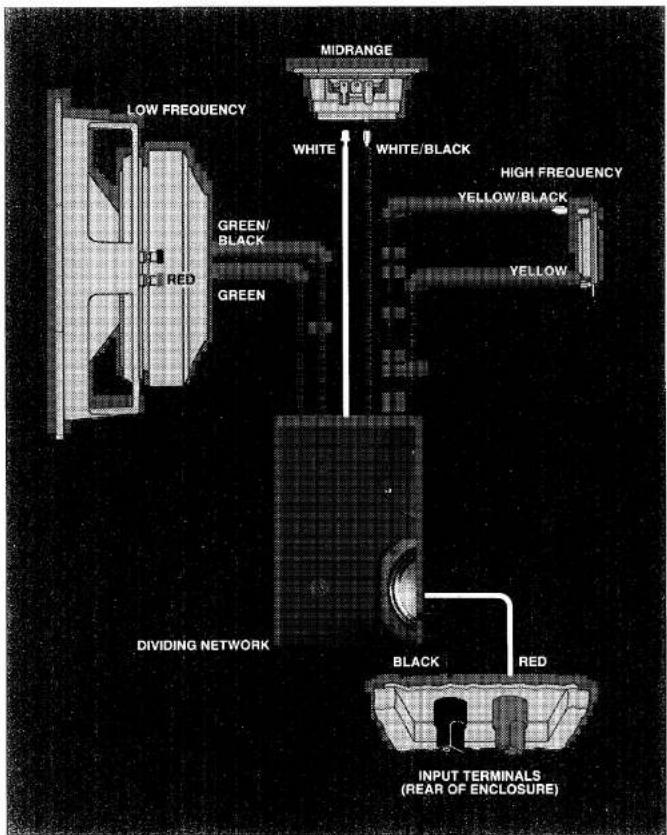
For each loudspeaker system, connect the wire from the black terminal to the amplifier output terminal labeled "common," "ground," (-), or colored black, and the wire from the red terminal to the amplifier terminal labeled "8 ohms," "8 Ω," (+), or colored red. If lamp cord is used, the two wires can be told apart by noting that one of the insulating jackets is smooth, while the other has a distinct ridge. Connecting both systems as described ensures in-phase operation; i.e., their cones will respond to a monophonic signal by moving simultaneously in the same direction, and not opposite to each other. (Note: Some amplifiers have a chassis grounding terminal, which is usually isolated from the other connectors. This should not be confused with the "ground" designation sometimes used to describe one of the terminals in each set of loudspeaker connections.)
The specified 8-ohm impedance rating is a nominal figure which suggests a connection giving the most efficient power transfer between amplifier and loudspeaker system.
natural_image
Simple diagram of a mechanical component with a curved arrow indicating rotation or motion (no text or symbols)
natural_image
Pure electrical circuit lines without any symbols-
Strip approximately 20 mm ( 34 in) of the insulation from the end of the wire. Twist the wire strands together.
-
Turn the terminal fully counter-clockwise, insert the wire, then turn the terminal clockwise until the wire is secured. Rotate the terminal by hand—do not force it.
PLACEMENT
Although JBL loudspeaker systems have wide dispersion, their sound is affected by their location. For example, bass response will be augmented if the enclosures are placed near adjoining room surfaces (i.e., in a corner, or on a wall near the floor or ceiling). Experiment before deciding on a final location for each system.
For the best possible stereo performance, the two loudspeaker systems should be arranged symmetrically on each side of the listener. As a general rule, the ideal listening location should be at the apex of an angle of 40^ between the two systems. The distance between the enclosures should be determined by their distance from the listener and by this 40^ listening angle.
Locating the high frequency driver at ear level usually gives the best results.
Note: Vertical orientation of the L110 is preferred for smoothest performance and best stereo imaging.
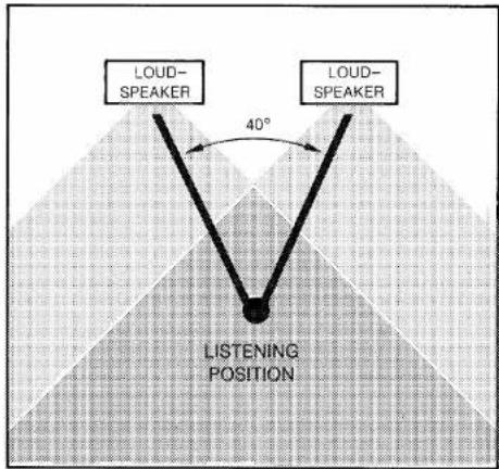
40° Listening Angle
Sound from each loudspeaker blends to form a stereo
"image." The stereo image will be intensified and the area of best stereo perception increased if the two systems are turned slightly toward the preferred listening position.
The crossover network installed in the L110 is provided with controls to compensate for listening room acoustics by adjusting the output of the high frequency and midrange loudspeakers.
The L110 should be adjusted while playing typical program material with the preamplifier or receiver tone controls set for flat response. With the system standing upright, begin by setting the loudspeaker system controls at the 12 o'clock position. Turning the controls counter-clockwise will diminish high frequency and midrange level; turning them clockwise will increase response in these ranges. Adjust the high frequency output first. Once the controls have been set for the most pleasing overall results, compensation for differences in program material should be made with the tone controls on the preamplifier or receiver.
ADJUSTING THE SYSTEM
natural_image
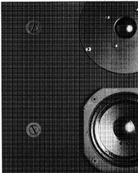
Close-up of a speaker emitting sound waves on a grid background (no text or symbols visible)High frequency and midrange controls are located on the front of the enclosure, behind the removable grille. Each is closest to the component it regulates.
POWER CAPACITY
The L110 produces sound at comfortable listening levels when driven by an amplifier with an output of as little as 10 watts continuous sine wave per channel.* However, for reproduction of the full dynamic range of contemporary recordings, a high quality amplifier delivering up to 250 watts continuous sine wave per channel will provide the best performance. Such an amplifier has the reserve power necessary for accurate reproduction of transients, which can reach momentary peaks equivalent to ten times the average power level. JBL products are unique in this ability to combine high efficiency with the ability to handle large amounts of power.
"The continuous sine wave rating of amplifier power is the most stringent method currently used in the audio industry. Many amplifier manufacturers use the term "watts rms" as a direct equivalent to the more meaningful "watts continuous sine wave."
The L110 enclosure panels are made of dense compressed wood, superior to solid wood in its acoustic properties. The veneer on the four side panels is solid American black walnut. To achieve the greatest strength and resistance to vibration, all panels are made of 19 mm (3/4 in) or 25 mm (1 in) stock, and all joints are hand-fitted and wood-welded.
The enclosure features a hand-rubbed oil finish. As the oil penetrates into the walnut, the veneer may appear to be drying out. Many owners therefore re-oil the enclosure from time to time. With each application of oil the beauty of the finish will be enhanced, and a rich, warm patina will eventually appear.
To re-oil the enclosure, use any of the several clear oil finishing preparations available at furniture or hardware stores. Apply a liberal amount of the oil over the entire surface of the veneer. After fifteen minutes, wipe the surface with a clean, soft, dry cloth.
Small surface scratches can usually be removed by gently rubbing them out with #4/0 steel wool and applying oil to the entire panel. When using steel wool, press very lightly and rub only in the direction of the grain. Deep scratches or serious damage should be repaired only by a qualified furniture refinisher.
Every component of every JBL system is designed and produced to the most rigorous standards in the audio industry:
☐ JBL loudspeaker frames are massive cast structures, machined to exacting tolerances.
☐ Magnetic assemblies are made of low-reluctance iron, energized by large, high-grade magnets.
☐ Voice coils are wound by hand and held within one turn of design specifications.
- Cones are designed for the best possible combination of stiffness, density and weight.
☐ Each individual component, the enclosure, and finally the system as a whole must withstand a series of rigorous quality control tests and inspections.
LOW FREQUENCY LOUDSPEAKER—The low frequency loudspeaker is a powerful 250 mm (10 in) driver, designed specifically for accurate, distortion-free performance in the L110 enclosure. The back of the cone is coated with Lansaplas, which damps extraneous vibrations and gives the moving assembly optimum mass, stiffness and density. The 4.7 kg (10 ^1/4 lb) magnetic assembly, unusually large in relation to cone size, makes this loudspeaker at once efficient and able to handle large amounts of power, and contributes to its superior transient response. The low frequency loudspeaker exhibits smooth response to frequencies beyond 3 kHz, well above the 1 kHz crossover point, so the transition to the midrange loudspeaker is gradual and imperceptible.
ENCLOSURE
COMPONENTS
natural_image
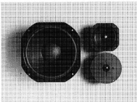
Three black mechanical components on a grid background, no visible text or symbolsLoudspeaker System Components
10 inch Low Frequency Loudspeaker
5 inch Midrange Transducer
1 inch Dome Radiator
MIDRANGE LOUDSPEAKER—The 130 mm (5 in) midrange loudspeaker, housed within an isolated sub-chamber to prevent detrimental interaction with the low frequency loudspeaker, delivers undistorted reproduction even at extreme volume levels. Its 22 mm (\% in) copper voice coil is large for a loudspeaker of this size, yielding exceptional transient response and efficiency. A very stiff cone reduces the possibility of cone breakup at very high power levels.
Because the midrange loudspeaker is more efficient than the low frequency loudspeaker, it operates well below its full potential, maintaining the substantial reserve dynamic range necessary to reproduce high intensity program peaks without strain or distortion. HIGH FREQUENCY LOUDSPEAKER—The 25 mm (1 in) high frequency loudspeaker is small enough for excellent dispersion and light and strong enough to provide high output easily. Its voice coil follows the circumference of the radiating surface rather than occupying the center; large for a high frequency unit, it provides high power handling capacity and remarkable transient response. Special clamping rings on the compliance ensure linear motion and prevent extraneous reflections. High frequency performance extends beyond the upper limit of human hearing. FREQUENCY DIVIDING NETWORK—The signal from the amplifier encompasses a wide range of frequencies. The frequency dividing network allocates each portion of the audio spectrum to the appropriate component of the loudspeaker system. To achieve blended performance, the drivers operate at diminishing output
levels above and below the stated crossover frequencies. Smooth, imperceptible operation of the network is vitally important; otherwise the listener would perceive the sound of individual components rather than that of an integrated loudspeaker system.
The L110 network incorporates impedance-leveling and phase-correcting circuitry, ensuring that the network operates in a nearly ideal manner through the transition frequencies. This circuitry, combined with the remarkable frequency response of the individual drivers, gives the L110 its exceptionally smooth performance.
The network incorporates controls that adjust the output of the midrange and high frequency drivers to compensate for listening room acoustics.
Should your JBL loudspeaker system require service, return it to the JBL dealer from whom it was purchased. If this is not possible, write directly to the JBL Customer Service Department, describing the problem as fully as possible. Products returned to the factory must be sent prepaid to JBL Customer Service Department, 8500 Balboa Boulevard, Northridge, California 91329, U.S.A.
SERVICE
Should it become necessary to remove the loudspeaker system components for testing or repair, disconnect the system from the amplifier or receiver and proceed as follows:
GRILLE—The grille is secured to the enclosure by dowel pins located near the corners of the enclosure. To remove the grille, grasp it by the top or bottom corners and pull gently. To replace the grille, reposition it on the enclosure and press lightly to reseat it on the dowel pins. The JBL emblem can be turned to read correctly whether the system is positioned vertically or horizontally. When rotating the JBL emblem, remove the grille and support the fastener behind the grille cloth with your free hand.
LOW FREQUENCY LOUDSPEAKER—Place the enclosure on its back on a clean, padded surface. The low frequency loudspeaker is mounted from the front of the baffle panel, held in place by four Allen-head screws threaded into T-nuts on the back of the panel. Unscrew the machine screws using a 18 -inch Allen wrench. Do not apply pressure that might dislodge the T-nuts. Then gently lift the edge of the loudspeaker frame from the baffle panel, disconnect the wires at the binding posts on the loudspeaker frame and remove the unit from the enclosure. Save the sealing gasket to re-use when the unit is replaced.
COMPONENT REMOVAL
| MIDRANGE LOUDSPEAKER—The midrange loudspeaker is held in place by Allen-head screws and T-nuts at each corner of its frame. Remove the screws with a 5/64-inch Allen wrench, lift the unit from the enclosure, and disconnect the leads at the tab connectors.HIGH FREQUENCY LOUDSPEAKER—The high frequency loudspeaker is secured by three Allen-head screws threaded into T-nuts. Carefully take out the mounting screws using a 3/32-inch Allen wrench and lift the assembly out of the enclosure. Disconnect the two leads from the dividing network at the tab connectors on the back of the frame.DIVIDING NETWORK—Remove the loudspeakers and pull the wire leads from the midrange sub-chamber so that they fall into the enclosure. The high frequency and midrange controls must be removed before removing the network. Place a piece of masking tape on the panel surface to prevent scratches, then slip a thin screwdriver blade under the lip of the bezel that surrounds the control knob and lift the bezel from the baffle panel. With needle-nose pliers, pull the control knob from the shaft, remove the retaining nut with a 12 -inch nut driver, then lower the control into the enclosure. The control shaft is fitted with a spacer that should be retained for reassembly. The network itself is mounted on the back panel of the enclosure and held in place by six Phillips-head screws. Remove these screws,then lift the network out of the enclosure through the low frequency loudspeaker opening.REPLACEMENT—Reverse the removal procedure to replace the loudspeaker system components. Mounting screws should be tightened evenly in several stages to avoid warping the frame, and only enough to prevent air leaks between the components and the enclosure. Avoid using excessive force. When reconnecting the wire leads, follow the diagram on page 10. | |
| FOR ADDITIONAL INFORMATION | If you have difficulty in achieving the fine performance of which your JBL loudspeaker system is capable, consult the JBL dealer from whom the system was purchased. He has the knowledge required to provide expert advice and assistance. If for some reason the JBL dealer is unable to assist you, write directly to the JBL Technical Services Department, explaining the difficulty in detail. |
| SPECIFICATIONS | JBL has traditionally refrained from publishing data for which no widely accepted test procedure has been established. In the absence of such standards, any laboratory can legitimately produce a variety of values, depending on the conditions selected. |
Low Frequency Loudspeaker
| Nominal Diameter | 250 mm | 10 in | |
| Voice Coil | 76 mm (3 in) edgewound copper ribbon | ||
| Magnetic Assembly Weight | 4.7 kg | 1014 lb | |
| Flux Density | 1.05 tesla (10,500 gauss) | ||
| Sensitivity ^1 | 89 dB, 1 watt, 1 m (3.3 ft) | ||
Midrange Loudspeaker
| Nominal Diameter | 130 mm | 5 in |
| Voice Coil | 22 mm (7⁄8 in) copper | |
| Magnetic Assembly Weight | 0.74 kg | 1 12 lb |
| Flux Density | 1.4 tesla (14,000 gauss) | |
| Sensitivity ^2 | 91 dB, 1 watt, 1 m (3.3 ft) | |
High Frequency Loudspeaker
| Nominal Diameter | 25 mm | 1 in |
| Voice Coil | 25 mm (1 in) aluminum | |
| Magnetic Assembly Weight | 0.68 kg | 112 lb |
| Flux Density | 1.4 tesla (14,000 gauss) | |
| Sensitivity ^3 | 90 dB, 1 watt, 1 m (3.3 ft) | |
General
| Finish | Oiled walnut |
| Grille | Blue, brown or semi-transparent black fabric |
| Dimensions | 597 mm x 362 mm x 286 mm deep23 12 in x 14 14 in x 11 14 in deep |
| Shipping Weight | 24 kg 53 lb |
System
| Nominal Impedance | 8 ohms |
| Dispersion4 | 150° at 15 kHz, 90° at 20 kHz |
| Crossover Frequencies | 1 kHz, 4 kHz |
| System Sensitivity5 | 89 dB, 1 watt, 1 m (3.3 ft) |
| Maximum Recommended Amplifier Power | 250 watts per channel |
- Averaged from 100 to 500 Hz, within 1 dB.
- Averaged from 1 to 3 kHz, within 1 dB.
- Averaged from 5 to 20 kHz, within 1 dB.
- The angle through which output diminishes no more than 6 dB relative to output on axis.
- All sensitivities are measured under hemispherical free-field conditions. In a room, an additional 1 to 3 dB would be realized.
JBL continually engages in research related to product improvement. New materials, production methods, and design refinements are introduced into existing products without notice as a routine expression of this philosophy. For this reason, any current JBL product may differ in some respect from its published description but will always equal or exceed the original design specifications unless otherwise stated.
LOUDSPEAKER SYSTEM WIRING