SY89222L - Kategooriata Microchip - Tasuta kasutusjuhend
Leidke seadme juhend tasuta SY89222L Microchip PDF-formaadis.

Kasutajate küsimused teemal SY89222L Microchip
0 küsimus selle seadme kohta. Vastake nendele, mida teate, või esitage oma.
Esita uus küsimus selle seadme kohta
Laadige alla juhend oma Kategooriata PDF-formaadis tasuta! Leidke oma juhend SY89222L - Microchip ja võtke oma elektrooniline seade uuesti kätte. Sellel lehel on avaldatud kõik teie seadme kasutamiseks vajalikud dokumendid. SY89222L kaubamärgi Microchip.
KASUTUSJUHEND SY89222L Microchip
General Description
The SY89222L and SY89322V evaluation boards are designed for convenient setup and quick evaluation of these devices.
The evaluation board standard configuration is AC-coupled for direct interface to a 50Ω compatible oscilloscope without split supplies. For applications that require a DC-coupled configuration, step-by-step instructions for modifying the board are included.
The boards are fully assembled and tested. All data sheets and support documentation can be found on Micrel's web site at www.micrel.com.
Features
• SY89222L: Single +3.3V power supply
• SY89322V: Single +3.3V or +5V power supply
• AC-coupled configuration for ease-of-use
• I/O interface includes on-board termination
• Fully assembled and tested
• Reconfigurable for DC-coupled operation
Related Documentation
- SY89222L, 3.3V Dual TTL-to-Differential PECL Translator data sheet
- SY89322V, 3.3V/5V Dual LVTTL/LVCMOS-to-Differential LVPECL Translator data sheet
Evaluation Board
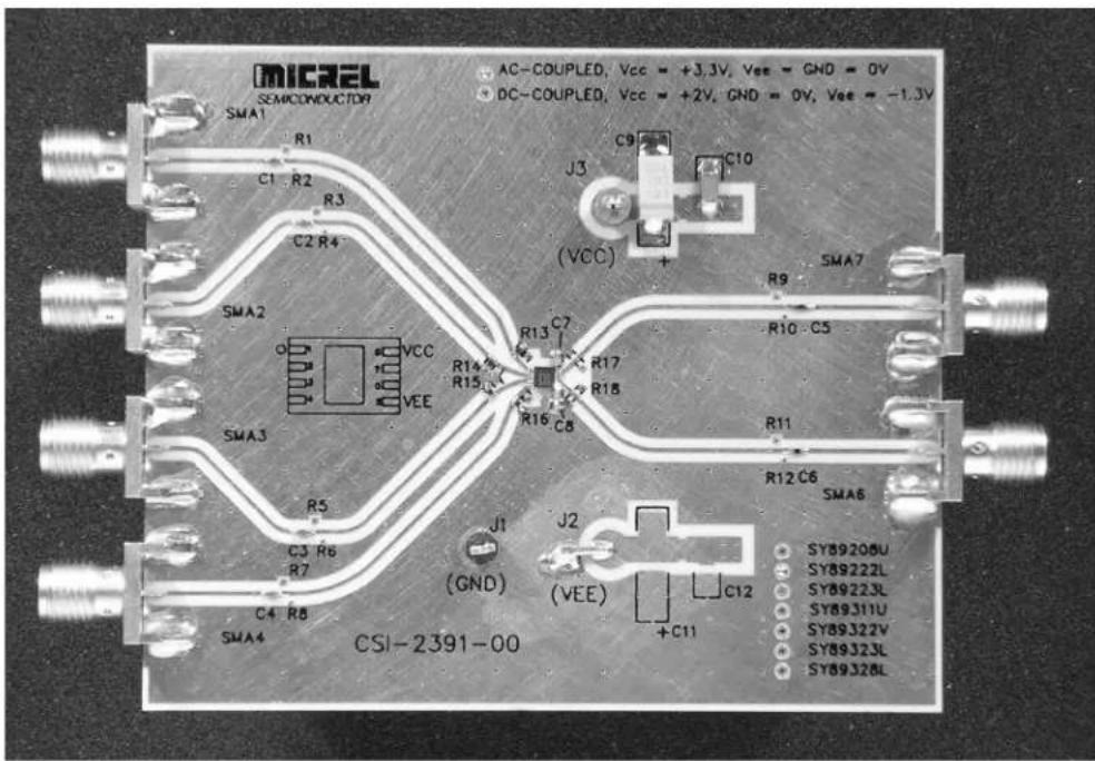
Evaluation Board Description
The SY89222L and SY89322V share a common evaluation board. The individual evaluation boards are labeled to identify the specific device and the configuration, either AC-coupled or DC-coupled configuration for that board.
The default configuration for the board is the AC-coupled configuration and all boards are shipped with this configuration. The choice between two configurations offers the user flexibility in selecting the board that is right for his particular application.
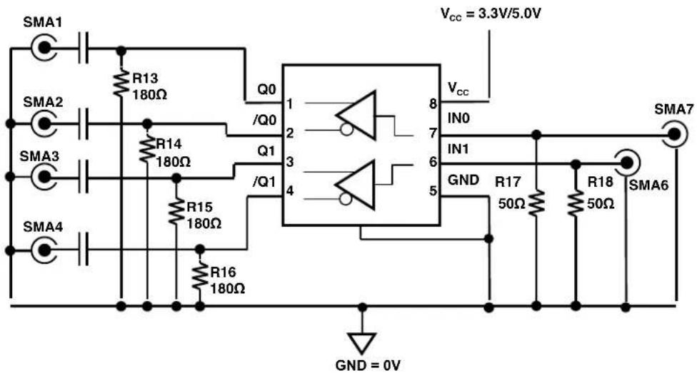
AC-Coupled Evaluation Board: Direct 50Ω Scope Interface
The AC-coupled configuration is suited to most customer applications and is preferred by the majority of users because of its ease-of-use. It requires only a single power and offers the most flexibility in interfacing to a variety of signal sources.
The AC-coupled configuration is suited to most customer applications and is preferred by the majority of users because of its ease-of-use. It requires only a single power supply of either 3.3V + 10% or 5.0V + 10% and offers the most flexibility in interfacing to a variety of signal sources.
DC-Coupled Evaluation Board
For DC-coupled operation, the board can be modified to interface directly to a PECL input on another device.
Step-by-step instructions for modifying an AC-coupled evaluation board for DC-coupled operation are supplied in the “Modifying your AC-Coupled Board for DC-Coupled Operation” section.
Evaluation Board
| I/O | Power Supply | V_cc | GND | V_EE | R15-R16 | C7-C8 |
| DC-In/AC-Out | 2.5V | +2.5V | 0 | 0 | 50Ω | 0.1μF |
| DC-In/AC-Out | 3.3V | +3.3V | 0 | 0 | 100Ω | 0.1μF |
Table 1. SY89222L/SY89322V Configuration
AC-Coupled Evaluation Board Setup
Setting up the AC-coupled Evaluation Board
The following steps describe the procedure for setting up the evaluation board:
- Set the voltage setting for a DC supply to be either 3.3V or 5.0V depending on your application and turn off the supply.
- Connect the GND terminal to the negative side of a DC power supply. This is the 0V ground potential.
- Connect the V_cc terminal to the positive side of a DC power supply.
- Turn on the power supply and verify that the power supply current is <80mA.
-
Turn off the power supply.
-
Using a single-ended signal sources set the V_OL ≤ +0.4V and the V_OH ≥ +2.4V . Turn off or disable the outputs of the signal source.
- Using 50Ω impedance coaxial cables, connect the signal sources to the inputs on the evaluation board (SMA6 and SMA7).
- Using equal length 50Ω impedance coaxial cables, connect the outputs of the evaluation board (SMA1, SMA2, SMA3 and SMA4) to the oscilloscope or other measurement device that has an internal 50Ω termination. If only 1 output of a pair is used, the unused output must be terminated with a 50Ω load.
- Turn on the power and verify the current is <80mA.
- Enable the signal source and monitor the outputs.
DC-Coupled Evaluation Board Setup
When DC-coupling is necessary: Interfacing to another system
For applications where AC-coupling is not appropriate, the board can be reconfigured for DC-coupled operation. An example where DC-coupling is required is if the outputs will not be monitored by a scope with a 50Ω termination to ground, but will be driving another device with LVPECL inputs. The LVPECL inputs of the destination device must be terminated with the normal PECL load of 50Ω to V_CC - 2V .
Reconfiguring an AC-Coupled Board into a DC-Coupled Board
The following procedure details the steps for converting an AC-coupled board to a DC-coupled board.
- Remove resistors R13, R14, R15 and R16 from the outputs.
- Replace capacitors C1, C2, C3 and C4 with 0Ω resistors.
- For easy identification, remove the solder dot from the via adjacent to the AC-coupled silkscreen label on the front of the board and add a solder dot to the DC-coupled via.
Setting up the DC-coupled Evaluation Board
The following steps describe the procedure for setting up the DC-coupled evaluation board:
- Set the voltage setting for a DC supply to 3.3V or 5.0V and turn off the supply.
- Connect the GND terminal to the negative side of a DC power supply. This is the 0V ground potential.
- Connect the V_cc terminal to the positive side of a DC power supply
- Turn on the power supply and verify that the power supply current is <80mA.
- Turn off the power supply.
- Using single-ended signal sources set the V_OL = 0.4V and V_OH = 2.4V . Turn off or disable the outputs of the signal source.
- Using 50Ω impedance coaxial cables, connect the signal sources to the inputs on the evaluation board (SMA6 and SMA7).
- Using equal length 50Ω impedance coaxial cables, connect the outputs of the evaluation (SMA1, SMA2, SMA3 and SMA4) to the destination device that has the 50Ω terminations to V_cc -2V.
- Turn on the power and verify the current is <80mA.
Bill of Materials
| Item | Part Number | Manufacturer | Description | Qty. |
| C1, C2, C3, C4 | VJ0402Y104KXXAT | Vishay^(1) | 0.1μF, 25V, 10% Ceramic Capacitor, Size 0402, X7R Dielectric | 4 |
| C5, C6 | CRCW0402000Z | Vishay^(1) | Replace capacitor with resistors: 0Ω, 1/16W, 5% Thick-film Resistor, Size 0402 | 1 |
| C7,C8 | VJ1206Y103JXJAT | Vishay^(1) | 0.01μF, 25V, 10% Ceramic Capacitor, Size 0402, X7R Dielectric | 2 |
| C9 | 293D685X0025B2T | Vishay^(1) | 6.8μF, 20V, Tantalum Electrolytic Capacitor, Size C | 1 |
| C10 | VJ1206Y103JXJAT | Vishay^(1) | 0.01μF, 25V, 10% Ceramic Capacitor, Size 1206 | 1 |
| R13, R14, R15, R16 | CRCW04021820F | Vishay^(1) | 182Ω, 1/16W, 5% Thick-film Resistor, Size 0402 | 4 |
| R17, R18 | CRCW040249R9F | Vishay^(1) | 49.9Ω, 1/16W, 5% Thick-film Resistor, Size 0402 | 2 |
| J1 | 5011K-ND | Digi-Key^(2) | PC Test point Multi-purpose Black | 1 |
| J3 | 5010K-ND | Digi-Key^(2) | PC Test point Multi-purpose Red | 1 |
| SMA1, SMA2, SMA3, SMA4, SMA6, SMA7 | 142-0701-851 | Johnson Components^(3) | Jack Assembly End Launch SMA | 6 |
| U1 | SY89222L or SY89322V | Micrel^(4) | Dual TTL/LVTTL-to-Differential PECL/LVPECL Translator | 1 |
Additional Components for DC-Coupled Evaluation Board
| Item | Part Number | Manufacturer | Description | Qty. |
| C1, C2, C3, C4 | CRCW0402000Z | Vishay(1) | Replace capacitor with resistors: 0Ω, 1/16W, 5% Thick-film Resistor, Size 0402 | 4 |
Notes:
- Vishay: www.vishay.com
- Digi-Key: www.digikey.com
- Johnson Components: www.johnsoncomponents.com
- Micrel, Inc.: www.micrel.com
Evaluation Board Layout
PC Board Layout
The evaluation boards are constructed with Rogers 4003 material and are coplanar in design fabricated to minimize noise, achieve high bandwidth and minimize crosstalk.
| L1 | GND and Signal |
| L2 | GND |
| L3 | V_CC and V_EE |
| L4 | GND and Signal |
Table 2. Layer Stack
Micrel Cross Reference
To find an equivalent Micrel part, go to Micrel's website at: http://www.micrel.com and following the steps below:
- Click on Dynamic Cross Reference
- Enter competitor's part number in the Dynamic Cross Reference field
- To download a PDF version of this information, click on the Cross Reference PDF tab
HBW Support
Hotline: 408-955-1690
Email Support: HBWHelp@micrel.com
Application Hints and Notes
For application notes on high speed termination on PECL and LVPECL products, clock synthesizer products, SONET jitter measurement, and other High Bandwidth product go to Micrel Semiconductors website at http://www.micrel.com/. Once in Micrel's website, follow the steps below:
- Click on "Product Info".
- In the Applications Information Box, choose "Application Hints and Application Notes."
MICREL, INC. 1849 FORTUNE DRIVE SAN JOSE, CA 95131 USA
TEL +1 (408) 944-0800 FAX +1 (408) 474-1000 WEB http://www.micrel.com
The information furnished by Micrel in this data sheet is believed to be accurate and reliable. However, no responsibility is assumed by Micrel for its use. Micrel reserves the right to change circuitry and specifications at any time without notification to the customer.
Micrel Products are not designed or authorized for use as components in life support appliances, devices or systems where malfunction of a product can reasonably be expected to result in personal injury. Life support devices or systems are devices or systems that (a) are intended for surgical implant into the body or (b) support or sustain life, and whose failure to perform can be reasonably expected to result in a significant injury to the user. A Purchaser's use or sale of Micrel Products for use in life support appliances, devices or systems is a Purchaser's own risk and Purchaser agrees to fully indemnify Micrel for any damages resulting from such use or sale.
© 2004 Micrel, Incorporated.