KP1 - Multimeeter Sanwa - Tasuta kasutusjuhend
Leidke seadme juhend tasuta KP1 Sanwa PDF-formaadis.

Kasutajate küsimused teemal KP1 Sanwa
0 küsimus selle seadme kohta. Vastake nendele, mida teate, või esitage oma.
Esita uus küsimus selle seadme kohta
Laadige alla juhend oma Multimeeter PDF-formaadis tasuta! Leidke oma juhend KP1 - Sanwa ja võtke oma elektrooniline seade uuesti kätte. Sellel lehel on avaldatud kõik teie seadme kasutamiseks vajalikud dokumendid. KP1 kaubamärgi Sanwa.
KASUTUSJUHEND KP1 Sanwa

KP1
VOLT TESTER
INSTRUCTION MANUAL
SANWA ELECTRIC INSTRUMENT CO, LTD.
Dampa Bdg. 1-4 Sofakanda 2 Chome
Chiyoda-K, 1961, Japan
CE

This manual employs soy ink.
01-141020103010
[1] SAFETY PRECAUTIONS
Before use, read the following safety precautions.
Thank you for purchasing our voltage faster equipped with the electric field selection facility panel KP1.
Before use, please read this manual thoroughly to ensure correct and safe use. After reading it, keep it together with the product for reference to it when necessary.
Using the product in a manner not specified in this manual may cause damage to the protection function of the product.
The instructions given under the headings of "WARNING" and "CAUTION" must be followed to prevent accidental burn and electric shock.
1-1 Explanation of warning symbols
The meanings of the symbols used in this manual and attached to the product are as follows:
△: Very important instructions for safe use.
• The warning messages are intended to prevent accidents to
operating personnel such as sum and electric shock.
- The caution messages are intended to prevent incorrect ordering which may remove the product.
- : Refos to Registration Manual before use
□: Double or nonlinear rating - Group
- Circuit continuity buzzer - Backleft
1-2 Warning instructions for safe use
WARNING
The following instructions are intended to prevent injury such as burn and electric shock. Be sure to follow them when using the instrument:
-
This instrument is a voltage tester equipped with the electric field detection facility. Do not use it with an electric circuit exceeding 1000 V.
-
Voltages over DC 70 V or AC 35 V rms (48.7 V peak) are hazardous to human body. Take care so as not to touch them.
-
Never input signals exceeding the maximum rated input value (see 1-3).
-
Never use the instrument for measuring a line connected to equipment that may generate induced or surge voltage (such as a motor) because an input exceeding the maximum allowable overload input may be applied.
-
Never use the instrument if the instrument or test seeds are damaged or broken.
-
Never use the instrument with the case or battery to remove.
-
During measurement, do not hold the instrument by a position on the test pin side of the barrier on the test probe.
-
Never use the instrument when it is wet or with wet hands.
- Never attempt repair or modification, except for battery replacement.
- Perform start-up inspection and inspect the instrument at least once a year.
- This instrument is for indoor use only.
- Do not use the instrument in a method other than specified. Otherwise, the protection function may be spoiled.
CAUTION
-
Accurate measurement may be impossible near a source of strong magnetic field such as a transformer or large current line, near a source of electromagnetic wave such as a wireless device or near a charged object.
-
This instrument may malfunction or the measurement result may become abnormal if this instrument is used with a special waveform such as that of an inverter circuit.
1-3 Overload protection
| Mode | Display | Max. rated input | Max. over 60 protection input |
| Self-freez | SELF | ACV 05-1000 V | 1050 V min, 1450 V peak |
| Auto-schattering voltage measurement | Auto | ||
| Electro-folic detection | EF |
[2] APPLICATIONS AND FEATURES
2-1 Applications
This instrument is a voltage tester of the RMS value response type equipped with the electric field detector facility. It is designed for measurements in the ranges specified by IEC 61010-1 CAT, IV 600 V and CAT, III 1000 V.
Recent multilinstruments have been increasing the facilities and becoming capable of measuring a larger variety of items in simpler ways. Nevertheless, this trend also means that the risk of operation mistake is increasing because of the presence of facilities that are not required by all of the users.
This instrument has been designed to meet the actual needs of the fields of electrical equipment maintenance by prioritizing the usage without operation metives, reducing the size for higher portability and limiting the facilities to voltage measurement and electric field detection while complying with safety standards. It is suitable for voltage measurement and electric field detection of low-voltage lines and equipment.
2-2 Features
- Safe use with low-voltage equipment — IEC61010 CAT. IV 600 V and CAT. III 1000 V compatibility
- Single-button system — Easy operation for preventing operation mistakes
• Auto Identification of AC or DC voltage — AC measurement in true RMS value.
- Easy identification of 24 V type FA control panel voltage — The backlight color changes at 20 V or more
• Auto hold — The result of the last measurement is held automatically.
• Self-res: — Checking failures of the LCD or deconnection of a level wire.
• AC electric field detection— Both contact and noncontact
• Designed to fit the chest pocket of the working uniform
• LED light for illuminating the working site.
Measurement Category (Overvoltage Category)
Measurement Category II (CAT, III:
Line on the primary side of equipment with power cord to be connected to the receptacle.
Measurement Category III (CAT. III):
Line from the primary side of branch of equipment which directly takes in electricity from a distribution board to the receptacle.
Measurement Category IV (CAT. IV):
Line from the service conductor to the distribution board.
[3] NAME OF COMPONENT UNITS
3-1 Main unit and test leads
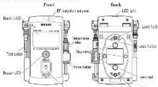
Praun Select barre.
![Sanwa KP1 - [3] NAME OF COMPONENT UNITS - 2](/content/2026/05/1094545/images/591df30848aee5c30ba38ea74559bec0640299b116708a55b36aeab40ab55e85.jpg)
3-2 Display
![Sanwa KP1 - [3] NAME OF COMPONENT UNITS - 3](/content/2026/05/1094545/images/eefaf30fe6682551234ae9e0d49ab05d43037b991e31894e205e8842eff7a19c.jpg)
[4] DESCRIPTION OF FUNCTIONS
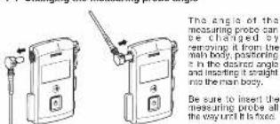
4-1 Changing the measuring probe angle
4-2 Power/Select button
The function of the Power/Select button varies depending on the period. It is pressed. In this manual, we use the term "push" for the action of pressing the button temporarily and the term "hold" for the action of pressing and holding the button for more than one second.
Hold this button to turn the instrument ON/OFF. Note that the instrument cannot be turned OFF while it is accepting an input.
Push the button while the instrument is ON to switch the measurement modes.
The instrument is in the self-test mode (56)Rayod) when it is turned ON. Thereafter, each press of this button switches the modes in the following cycle. Ifor the description of each mode, see(5) MEASUREMENT PROCEDURE,
Auto-identifying voltage measurement mode ( R_Auto displayed) EF mode (EF displayed) = Auto-identifying voltage measurement mode = - (repeat)
4-3 Auto power OFF
When the instrument is left without input for about one minute since the last operation, Auto power OFF turns automatically the display and the power of the instrument OFF. To recover from the auto power OFF, hold the Power/Select button for more than one second.
4-4 Low battery alarm
When the built-in batteries have been discharged and the battery voltage has dropped to below about 2.5 V, then appears on the display. When this mark appears, replace both about the two batteries with new ones. If the battery voltage drops below about the 2.5 V, then appears on the LCD and the instrument becomes unable to continue measurement.
4-5 Backlight and LED light
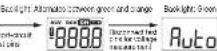
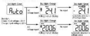
The LCD green backlight and the LED light light when the instrument is turned ON. The backlight color changes to orange when the input is AC or DC and 20 V or more, or when the AC live wire is detected in the EF mode.
The light cannot be turned OFF except by turning the instrument OFF.
4-6 Self-test
This self-test checks disconnection of the test lead wires, lack of display segments and failure of the buzzer and buzzer LED light. For details, see 5-2 Self-test mode.
4-7 AC/DC auto-identifying voltage measurement
When an input of 5 V or more is applied in the self-test or auto-identifying voltage measurement mode, the instrument automatically identifies whether the input is an AC or DC voltage and displays the measured value.
4-8 Auto hold
When the probe is separated from the measurement target during auto-identifying voltage measurement or when the input drops below about 5 V, the instrument automatically holds the last measurement value displayed on the LCD. During auto hood DH appears on the LCD and the displayed value flashes.
A numeric value other than the measured value may appear momentarily before the hold value is displayed, but this is not malfunction.
4-9 EF (Electric Field) detection: EF button
This EF detection identifies the presence of voltage in a simple manner by detecting an electric field generated by an AC voltage.
For details, see 5-4 EF (Electric Field) detection.
4-10 AC detection method
This instrument employs the RMS (Root-Mean-Square) method and indicates the magnitude of AC current as the same amount of work as DC. RMS values of sinusoidal waves and such non-sinusoidal waves as square and chopping waves can be measured by the true RMS circuit. [The input signal measurement value is used as the scale of the actual input signal power so it is therefore measured as a more effective value than the value obtained by average detection.]
4-11 CF (Cresl Factor)
The CF (Crest Factor) indicates the peak value of a signal divided by its RMS value. With most common waveforms such as sinusoidal and choosing waves, the CF is relatively low.
With waveforms similar to pulse trains with low duty cycle, the CF is high. For the voltages and CFs of typical waveforms, see the table below. The CF of measurements should be 2 or less.
| Spectral wave | Input Waveform | 2 to 4MHz Vp | Vp/16Vp Square & Vector Wave | Average Value Vp/Vp | Fixed Factor Vp/vms | Current Factor Vp/vms |
| 2 | 2Vp | 3 | 22 | |||
| ± 0.75Vp | - 1.434 | ± 1.111 | ||||
| Square wave | Vp | Vp | Vp | Vp | 1 | 1 |
| 2 | 12 | 3 | 3 | |||
| ± 0.57Vp | ± 0.5Vp | - 1.782 | - 1.155 | |||
| Cropping wave | Vp | Vp | 2 | 12 | 3 | 3 |
| ± 0.57Vp | ± 0.5Vp | - 1.782 | - 1.155 |
Voltages of Various Waveforms
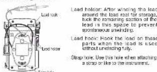
4-12 Storage of lead
[5] MEASURING PROCEDURE
WARNING
- Do not apply an input signal exceeding the maximum rated input value.
- During measurement, do not hold the instrument by a position on the test pin side of the border on the test probe.
- Use test loads matching the measurement category of the measured point.
5-1 Start-up inspection
Be sure to perform the start-up inspection before proceeding to measurement.
- Exterior check: Check the external view for irregularity caused by cropping etc.
- Check that the indicator is not lit. If it is lit, replace the batteries with new ones
- Accessories: Check that the test leads are free of irregularity such as using disconnection or attack.
• Make sure that the main unit and hand are not well with water, etc.
* If the display shows nothing, the batteries may be exhausted completely.
5-2 Self-test mode
① The LCD shows SELF when the instrument is turned ON.
② Short-circuit the test pres.
③ All of the numeric value segments and marks are displayed on the LCD and the backlight changes color between green and orange alternately. Confirm that the buzzer beaps and that the buzzer LED lights up.
* The instrument does not enter the self-test mode. If the wire of a test lead is disconnected.
④ When the test pine are disconnected, the instrument enters the auto-detecting voltage measurement mode, in which the LCD displays Auto.
Ecur bus general, Iacor LED
When a voltage of 5 V or more is input while SELF appears on the LCD, the instrument enters the auto-detecting voltage measurement mode and displays the value of the input voltage.
5-3 Auto-detecting voltage measurement
| Function (Auto detection) | Range |
| DCV | 5.0 - 999.9 V |
| ACV (45 - 400 Hz) | 5.0 - 999.9 V |
| Circuit continuity | Threshold 26 k - 500 kΩ or less |
① The LCD displays Roco when there is no input.
② When a voltage of 5 V or more is input, the instrument automatically selects whether it is an AC voltage (ACV) or DC voltage (DCV) and displays the corresponding mark together with the measurement value.
When a voltage of 20 V or more is input, it appears on the LCD and the backlight color changes from green to orange.
③ When the probe is removed from the measurement target of the input drops below about 5 V, the last measurement value is automatically held displayed on the LCD (data holds). In the data hold status, the DH mark appears and the held numerical value flashes.
* The data hold status continues until the next time a voltage is input or auto power OFF is activated.
④ When the voltage input is below about 1.5 V and the resistance is below the threshold value, the continuity buzzer beeps and the buzzer LED lights up. All of the numatic value segments and marks are displayed on the LCD and the backlight changes color between green and orange alternately.
When there is an input voltage between about 1.5 to 4.9 V, Ruto remains displayed and the instrument does not work even when the resistance is below the threshold.
Due to the high threshold value, the resistance may be as high as max. 500 kΩ even when the buzzer beep is generated.
5-4 EF (Electric Field) detection
WARNING
- Before proceeding to the EF detection, check the proper operation of this instrument using a known power source.
- During EF detection, do not hold the instrument by a position on the test pin side of the hands on the rope.
- Do not touch the power line because it is not always voltage-free but there may be a voltage below the detectable voltage.
① EF detection identifies the presence of AC voltage in a simplified manner by detecting the electric field generated by it.
The standard deviation level is from about 60 to 1300 V AC. When an electric fluid is selected, the LCD backlight changes color from green to orange, and the number of bars, the intervals of buzzer
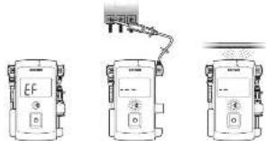
Beeds and the lasting interval of the buzzer LCD vary in the steps. ② Push the Power/Select button so that the LCD shows EF In the main numerical value display area.
- Check method
• Noncontact type measurement: Position the antenna as shown in the illustration (on the right side of the light when the instrument is viewed from the front). - Contact type measurement: Bring the test pin (either the black or red one) in contact with the target. More accurate EF detection is possible so that the buzzer does not beep and the display remains EF in the grounding phase.
* In certain cases in which the wrong is long, for example, EF may sometimes become *—* even on the grounding side.
Due to the high sensitivity, the EF sensing may be activated near an inverter generating high frequencies, even when it is as apart as more than some tons of centimeters from the instrument.
Blacklight Green Blacklight Orange
Undetected status Detected status
(Contact type)
Jazzicht Change
Detected status
(Noncontact type)
[6] MAINTENANCE AND INSPECTION
WARNING
- The following instructions are very important for safety: Read this manual thoroughly to ensure correct maintenance.
- Collaborate and inspect the instrument at least once a year to ensure safety and maintain its accuracy.
6-1 Maintenance and inspection
1) Appearance: Is the instrument not damaged due to failing or cause?
2. Tard, courts
• is a plug loose when it is inserted into the measured terminal?
• Is the cord of a test lead damaged?
- Is white coating exposed from the coating of a test lead?
If any of the above problems exists, stop using the instrument and contact us for repair or part replacement.
6-2 Calibration and inspection
For more information, please contact Sarwa's authorized agent / distribute service provider, listed in our website. See https://e-1/
SEE SECTION 1-2-4.
6-3 Cleaning and storage
CAUTION
-
The pane and case are not resistant to volatile solvent and must not be cleared with thinner or alcohol. If the instrument gets dirty, wipe with a soft cloth moistened with a small amount of water.
-
The panel and case are not resistant to heat. Do not pace the installed near heat-operating devices.
-
Do not store the instrument in a place where it may be subjected to vibration or noise. It may fall.
-
Do not store the instrument in places under direct sunlight, or hot, cold or humid places or places where condensation is anticipated.
-
If the instrument will not be used for a long time, remove the batteries.
6-4 Battery replacement
Batteries when the instrument is shipped:
A battery for monitoring has been installed prior to shipment from the factory. It may be discharged before the expiration of the described battery life.
*The battery for monitoring is a battery used to check the functions and performance of the product.
WARNING
- To avoid electric shock, do not remove the battery cover while an input is applied to the measured terminal or during measurement.
- Make sure that the instrument is set to OFF before replacing the behaviors.
① Unwind the test lead (black) from the lead reel so that the screws are exposed.
②. Using a Philips screwdriver, removes the two battery cover retaining
① Replace both of the two batteries in the battery holder with new ones by taking care of the polarity.
④ Attach the battery cover and retaining screws in the original positions.
* The battery cover incorporates a magnet so care is required when closing it.
[7] AFTER-SALE SERVICE
7-1 Warranty and provision
Sarwa offers comprehensive warranty services to its end-users and to its product retailers. Under Sarwa's general warranty policy, each instrument is warranted to be free from deforts in workmanship or materials under normal use for the period of one (1) year from the date of purchase. This warranty policy is valid within the country of purchase only, and applied only to the product purchases from Sarwa authorized agent or distributor.
Serve reserves the right to inspect all warranty claims to determine the extent to which the warranty policy shall apply. This warranty shall not apply to disposables batteries, or any product or parts, which have been subject to one of the following causes:
1. A failure due to improper handling or use that deviates from the instruction manual.
2. A failure due to inadequate repair or modification by people other than Service service persons.
- A failure due to causes not attributable to this product such as fire, flood and other natural disaster.
- Non-operation due to a discharged battery.
- A failure or damage due to transportation, relocation or dropping after the purchase.
7-2 Repair
Customers are asked to provide the following information when requesting services:
-
Customer name, address, and contact information
-
Description of the problem
-
Description of the product configuration
-
Model Number
-
Product Serial Number
-
Front of Data of Purchase
- Where you purchase the product
Please contact Sanva authorized agent / distributor / service provider, listed in our website, in your country with above information. An instrument sent to Sanva / agent / distributor without above information will be returned to the customer.
Binding
1) Prior to requeston repay, please check the following:
Capacity of the built-in battery, polarity of installation and discontinuity of the test needs.
2) Repair during the warranty period:
The failed instrument will be repaired in accordance with the conditions stipulated in 7-1 Warranty and provision.
3) Repair after the warranty period has been done.
• If it is expected that servicing can restore the original functioning of the
• The service charge or transport freight could sometimes become higher.
- The minimum retention period of the servicing performance parts of this product is six (6) years after the discontinuation of production. This period is equal to the servicing available period. However, the retention period of a part may be reduced if it becomes unavailable due to discontinuation of production of the part manufacturer, etc.
4) Productions than sending the product to be repaired:
To ensure the safety of the product during transportation, place the product in a box that is larger than the product 5 times or more in volume and fill cushion materials fully and then clearly mark "Repair Product Enclosed" on the box surface. The cost of sending and returning the product shall be borne by the customer.
7-3 SANWA web site
http://www.sarrea-instrument.co.jp
E-mail: exp_sales@sarwa-instrument.co.jp
[8] SPECIFICATIONS
8-1 General Specifications
| Operation method | S_max method |
| AC direction method | Two RMS |
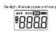
| Clocky | Numerical volat (Max. 9888 counts, with backlight temperature) |
| Balance range | ACV Approx. 3 min/ksec, DSS Approx. 5 min/ksec |
| Open range display | 100% is displayed |
| Potency switching | A vs (King "—" is employed) |
| Low battery direction | The 2DC indicator lights on the display when the supply voltage from the batteries drops below about 2.2 V, [dB], appears on the LCD and the instrument becomes made to continue measurement. |
| Operating water level conditions | Atmosphere more than 2500 m in air/box, environmental conditions are good |
| Operating temperature humidity ranges | Temperature: 5 pc 40 °C Humidity: 6 pc following without soundstacking; 6 pc 30 %R, 80 kWh 30 pc 40 °C, 700000000 decreased from BC 50Hz to 100 MHz |
| Storage temperature at-risk range | Temperature: -15 to +40 °C No more than 80 %RH without precipitation Temperature: +40 to +50 °C No more than 70 %RH without cooling otherwise (therefore the battery so often the instrument is not to be used for long time) |
| Temperature coefficient | At lower: 10 °C or above 20 °C, multiply accuracy by 30.5 pc = 1 °C |
| Power supply | LPG (MAA) also allowing battery: 1.5 V × 2 |
| Auto screw cell | The instrument power is set off OFF: 1 about 1 min, 10000000000000000000000000000000000000000000000000000000000000000000000000000000000000000000000000000 |
| Current consumption process | 200°C (A) during |
| Battery life | Approx. 20 seconds continuous measurement of 40 V/DC |
| Omicronfrequency | 1800p-900V/300V/mm / approx. 200 V (including battery use) |
| Battery sensors | IEC10101-1, IEC0101-2-208 GB, V 900 V / DC, E 1000 V, IEC0101-3-2, IEC10101-31 |
| EVO receive | IEC0101-3 |
| Accessories | Electrical machine, test loads (TL 36 Test probe load), TL 36 Test load (block approx. 1.5m, TL-601 TCC power block) |
8-2 Measuring ranges and accuracies
Accuracy-guaranteed temperature/humidity ranges
23 +5 °C, no more than 80 %RH, (without condensation)
■ And not be deployed.
Crest factor {CF}: < 2
rdg: Reading dgt: Lowest digit
ACV (AC voltage)
Measurement range 5.0 - 999.9 V. Accuracy = (1.7 %rdg - 5deg)
Note: Input impedance approx. 1.7 MO at 160 nF, frequency range 45 \~ 400 Hz
42.0001%
DCV (DC voltage)
Measurement range: 5.0 - 999.9 V. Accuracy: -0.7 %rdg = 5000) Note: Input impedance approx. 1.7 MD at 160 nF
The image is too blurry to recognize any text content.
Circuit continuity
Open Voltage: Approx. 0.6 V DC, Buzzer filter: 20 \~ 500 kJ
(1) 2017年1月1日
EF (Electric Field) detection
A voltage or electric field of about 60 V or more is detected. The bar graph and intermittent buzzer deeps change in five steps according to the field intensity.
Detection frequency: 50/60 Hz
Detection antenna: Top of the Instrument body
(see the right of the LED light)
Contact type EF detection: + ten
Accuracy calculation method
Example: RCV (MC village) measurement
Displayed name: 100.0 V
Range and accuracy: 500.9 V range, ±11.7%reg + 500
Error: (100.0 V × 1.7 V = 348) = 12.2 V
Taus vau x 100.0 V + 7.7 V (R/ftn 100.3 ft)
* In the 999.9 V range, the 5 dips consensus to (1.5) V
in the 000.5 range, the right corresponds to 0.5
The product specifications described in this manual and its appearance are subject to change without notice for improvement or other reasons.