P.I.P.-EDC - Kategooriata CROWN - Tasuta kasutusjuhend
Leidke seadme juhend tasuta P.I.P.-EDC CROWN PDF-formaadis.

Kasutajate küsimused teemal P.I.P.-EDC CROWN
0 küsimus selle seadme kohta. Vastake nendele, mida teate, või esitage oma.
Esita uus küsimus selle seadme kohta
Laadige alla juhend oma Kategooriata PDF-formaadis tasuta! Leidke oma juhend P.I.P.-EDC - CROWN ja võtke oma elektrooniline seade uuesti kätte. Sellel lehel on avaldatud kõik teie seadme kasutamiseks vajalikud dokumendid. P.I.P.-EDC kaubamärgi CROWN.
KASUTUSJUHEND P.I.P.-EDC CROWN

natural_image
Simple line drawing of a crown inside a rounded square frame (no text or symbols)P.I.P.-EDC
PROGRAMMABLE INPUT PROCESSOR
OWNER'S MANUAL
Distributed in North America as Crown: Exported as Amcron:
©1992 by CROWN INTERNATIONAL, INC.
Mailing Address:
P.O. Box 1000
Elkhart, IN 46515-1000
219/294-8000
Customer Service:
57620 C.R. 105
Elkhart, IN 46517
800/342-6939
Trademark Notice: Amcron ^® , Crown ^® , and P.I.P. ^® are registered trademarks of Crown International, Inc. Other trademarks are the property of their respective companies.
K80476-3
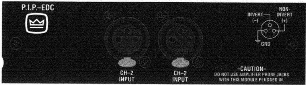
Fig. 1.1 P.I.P.-EDC
1 Welcome
Thank you for purchasing the Crown P.I.P.-EDC accessory. P.I.P. ^® modules are designed to install quickly into the rear panel of many Crown amplifiers. P.I.P. stands for 'Programmable Input Processor.' Their versatile features expand the capabilities of your amplifier and enable you to customize it for your particular needs.
The P.I.P.-EDC adds the features of a state-of-the-art error-driven and signal-driven compressor and variable subsonic (high-pass) filter to each input of your amplifier. Two conditions can cause the compressor circuits to activate: if either compressor receives an 'error' signal from the amplifier's
IOC^ (Input/Output Comparator) circuitry or if an excessively large input signal level is sensed. The compressor circuits activate ahead of all preamp circuitry, resulting in low distortion.
Each channel's compressor can operate independently or both channels can be tied together causing the compressors to track each other.
Balanced XLR connectors are provided for quick connection.
Feature Summary
☐ An Error-driven/signal-driven compressor for each channel.
☐ Fast or slow attack and release times can be set using DIP switches.
☐ Each compressor can be turned off.
☐ Variable subsonic (high-pass) filter.
2 Facilities
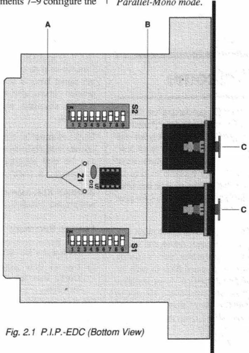
A. Tracking Jumper Z1
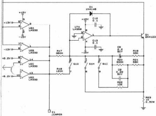
The addition of a jumper across these two solder holes (Z1) causes the compressors to track each other.
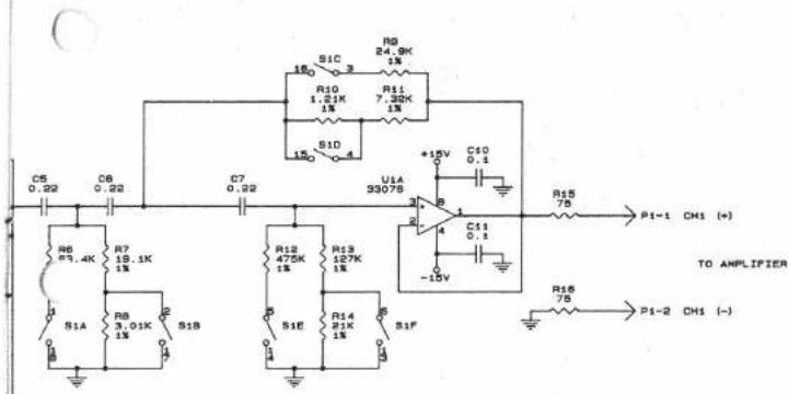
B. DIP Switch S1 & S2
A nine-segment DIP switch is provided for each channel. Segments 1–6 select the subsonic corner frequency and segments 7–9 configure the
compressor. S1 controls Channel 1 and S2 controls Channel 2.
C. Input Connector
A balanced XLR connector is provided for input to each channel. The pin assignments are labeled on the face of the P.I.P. Refer to your amplifier Owner's Manual for wiring details.
Important: Do not use the Channel 2 input and turn its level control off (full counterclockwise) if the amplifier is used in either Bridge-Mono or Parallel-Mono mode.
2-1 Facilities
3 Installation
The internal DIP switches (S1, S2) of the P.I.P.-EDC must be set prior to installation.
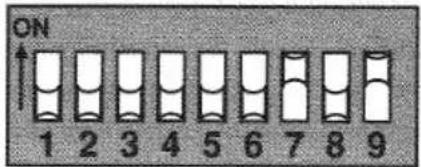
Fig. 3.1 S1/S2 DIP Switch
Please refer to the table in Figure 3.3 below for the functions of the different DIP switch settings. Notice that the corner frequency (-3 dB frequency) of each subsonic filter is set with the first six switch segments. The last three segments control each compressor.
Each compressor can be given a fast or slow attack or release time. The compressors can also be turned off. The attack time is dependent upon the release time. The table in Figure 3.2 gives approximate values for the different settings.
| Compressor Setting | Approximate Time | |
| Attack | Release | |
| Slow Attack / Slow Release | 5 msec | 900 msec |
| Slow Attack / Fast Release | 10 msec | 220 msec |
| Fast Attack / Slow Release | 1.25 msec | 900 msec |
| Fast Attack / Fast Release | 1.5 msec | 220 msec |
Fig. 3.2 Approximate Compressor Attack and Release Times
If desired, the compressors can be made to track each other by installing a jumper across the two unused solder holes labelled Z1 next to U7 and C12 (see 'A' in Figure 2.1).
| Function | DIP Switch (S1 or S2) | |||||||||
| 1 | 2 | 3 | 4 | 5 | 6 | 7 | 8 | 9 | ||
| Subsonic Filter | 36 Hz Corner Frequency | ON | ON | ON | ON | ON | ON | |||
| 32 Hz Corner Frequency | ON | OFF | ON | OFF | ON | OFF | ||||
| 28 Hz Corner Frequency | OFF | ON | OFF | ON | OFF | ON | ||||
| 24 Hz Corner Frequency | OFF | OFF | OFF | OFF | OFF | OFF | ||||
| Compressor | Slow Attack / Slow Release | OFF | OFF | OFF | ||||||
| Slow Attack / Fast Release | OFF | OFF | ON | |||||||
| Fast Attack / Slow Release | ON | OFF | OFF | |||||||
| Fast Attack / Fast Release | ON | OFF | ON | |||||||
| Compressor OFF | ON | |||||||||
Fig. 3.3 S1/S2 DIP Switch Settings
Installation Procedure
- Turn off the amplifier and unplug its power cable. If this is the first time this amplifier is being used, turn down the amplifier level controls.
- Remove the existing P.I.P. module (two screws) pulling straight out with firm pressure.
- Align the edge connector of the P.I.P. circuit board with the P.I.P. card rails (see Figure 3.4) and slide the P.I.P. into the rails.
- Firmly push the P.I.P.-EDC all the way in until it is seated against the mounting bracket.
- Secure it with the two screws and lock washers provided.
Important: The lock washers must be used so the chassis ground connection is secure.
- Plug in the amplifier and turn it on. If this is the first time you are using this amplifier, adjust the level controls for maximum desired loudness.
CAUTION: Do not use the amplifier phone jacks as inputs with this P.I.P. installed. Since the amplifier phone jacks are in parallel with the P.I.P. outputs, the phone jacks can be used as outputs to 'daisy chain' to other amplifier inputs. If you do this, remember that the signal feeding the other amplifiers will be filtered and compressed too.
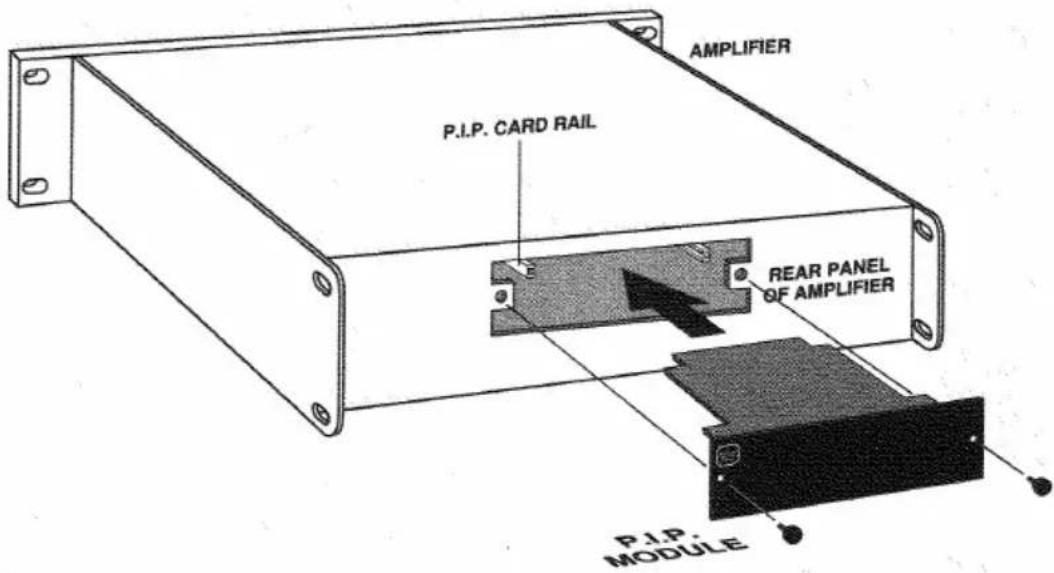
Fig. 3.4 Installing the P.I.P.
4 Specifications
Note: All specifications are referenced to a 0.775 V input signal.
Signal to Noise: Greater than 95 dB from subsonic filter corner frequency to 20 kHz.
Frequency Response: ±0.1 dB from 70 Hz to 30 kHz with subsonic filter corner frequency set to 36 Hz. +0, -3 dB from subsonic filter corner frequency to 30 kHz.
Harmonic Distortion (THD): Less than 0.01% THD at 1 kHz.
Common Mode Rejection: Greater than 65 dB at 1 kHz.
Crosstalk: Less than 0.5 mV at 20 kHz.
Connectors: 3-pin female XLR for each input.
Input Impedance: Nominally 30 kohms balanced. 15 kohms unbalanced.
Maximum Input Level: 35 VAC.
Maximum Output Level: +18 dB with 600 ohm load.
Nominal Gain: Unity ±0.5 dB.
Dimensions: 6 ^3 / 8 x 1 ^7 / 8 x 3 ^7 / _8 in (16.2 x 4.8 x 9.8 cm).

crown
P.I.P.-EDC
| HI-PASS FILTER | ||||||
| A | B | C | D | E | F | -3dB FREQ. |
| 1 | 1 | 1 | 1 | 1 | 1 | 36 Hz |
| 1 | 0 | 1 | 0 | 1 | 0 | 32 Hz |
| 0 | 1 | 0 | 1 | 0 | 1 | 28 Hz |
| 0 | 0 | 0 | 0 | 0 | 0 | 24 Hz |
| CONPRESSOR MODE | ||||
| 0 | H | I | ATTACK | DECAY |
| 0 | 0 | 0 | SLOW | SLOW |
| 0 | 0 | 1 | SLOW | FAST |
| 1 | 0 | 0 | FAST | SLOW |
| 1 | 0 | 1 | FAST | FAST |
| X | 1 | X | OFF | |
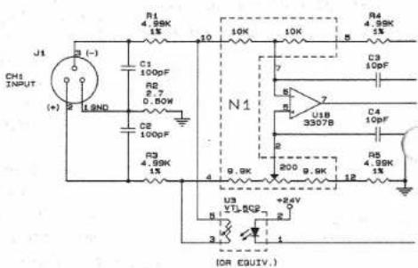
Only one channel shown.
P.I.P.-EDC
crown
Notes:
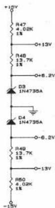
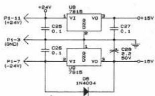
- All resistor values are in ohms, ¼ W, 5% unless otherwise specified.
- All capacitor values are in micro-farads unless otherwise specified.
- P1 pins 6, 8, 9, 10, 12, 13, 15-22 are not used.