Epica DGX 288 Enclosure - Kategooriata AMX - Tasuta kasutusjuhend
Leidke seadme juhend tasuta Epica DGX 288 Enclosure AMX PDF-formaadis.

Kasutajate küsimused teemal Epica DGX 288 Enclosure AMX
0 küsimus selle seadme kohta. Vastake nendele, mida teate, või esitage oma.
Esita uus küsimus selle seadme kohta
Laadige alla juhend oma Kategooriata PDF-formaadis tasuta! Leidke oma juhend Epica DGX 288 Enclosure - AMX ja võtke oma elektrooniline seade uuesti kätte. Sellel lehel on avaldatud kõik teie seadme kasutamiseks vajalikud dokumendid. Epica DGX 288 Enclosure kaubamärgi AMX.
KASUTUSJUHEND Epica DGX 288 Enclosure AMX
Overview
The Epica DGX 288 Matrix Switcher with Simplex DXLink Fiber I/O Boards is configurable by size up to 288 Inputs/outputs. The Hardware Reference Manual – Epica DGX 288 Matrix Switcher contains complete documentation (including specifications and supported resolutions); visit www.amx.com.
Installation
IMPORTANT: This product must be installed within a restricted access location where access is through the use of a tool, lock and key, or other means of security, and is controlled by the authority responsible for the location. (This is due to access to hazardous energy levels from power supplies if boards are removed.) This product must be installed and maintained only by qualified technicians.
Rack Mounting
CAUTION: To prevent overheating, avoid placing high heat-producing equipment directly above/below enclosure. The system requires a minimum of 2 empty rack units above. Verify that the openings on top, front, and sides of enclosure are not blocked and do not have restricted airflow.
To rack mount the enclosure (requires a minimum of 3 people):
- While the shipping box containing the enclosure is still on the pallet, cut loose and remove the outer straps.
- Remove the cardboard tray from the top of the reusable shipping box. (The shipping box is mounted on wheels.)
- Lift the shipping box off of the pallet and unlock the 4 latches on the box's sides.
- Lift the top of the shipping box straight up and over the enclosure and set aside.
- Using the bottom of the shipping box, roll the enclosure into position.
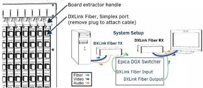
IMPORTANT: Do not use board extractor handles (FIG. 1) to lift or maneuver enclosure. - Using the hand-hold insets on the sides of the enclosure, lift and push the enclosure into the rack. Screw in 4 rack ear screws on each side, spread evenly.
- Supporting the enclosure as needed, screw in the remaining rack ear screws. CAUTION: For Input/Output boards, we recommend using cable management bars or some other type of cable management system to avoid damage to fiber cables.
Safety Recommendations for Laser Products
WARNING: DXLink Fiber units use laser transceivers, which are Class 1 Eye Safe per IEC 60825-1/CDRH requirements. While the Class 1 category indicates that the invisible laser used is safe, we recommend avoiding direct eye exposure when using any optical fiber products (see the OSHA directive in the product's manual). CAUTION: Use of controls or adjustments or performance of procedures other than those specified herein may result in hazardous radiation exposure.
Exercise caution to avoid direct eye exposure to invisible laser radiation. Follow the recommendations below whenever installing or working with fiber products.
☐ Be sure to apply the power only after all fiber connections are made and no fiber ends are exposed.
☐ Do not remove dust plugs from fiber connectors or the dust caps from the fiber cables until establishing connections; avoid direct eye exposure.
☐ Make sure all cables, including fiber cables, are correctly connected and/or terminated.
Before you unplug a fiber cable on an input port, disconnect the power on the Transmitter that is connected to the input.
Before you unplug a fiber cable on an output port, disconnect the switch for that output.
CAUTION: Do not severely bend or kink the fiber cable. Irreversible damage can occur. Refer to the physical limitations specified for the cable.
DXLink Fiber, Simplex Input/Output Boards – Transceiver Ports
The Simplex DXLink Fiber boards support Simplex or Duplex DXLink Fiber TXs and RXs; see applicable Quick Start Guide for details. Each board contains 16 fiber transceivers with one pair of IN/OUT ports per transceiver for connection to the appropriate Fiber TX or RX. Set up units according to the directions in their Quick Start Guide, installing a TX between each IN port and source device and an RX between each OUT port and destination device (FIG. 1).
flowchart
graph TD
    A["Board extractor handle"] --> B["DXLink Fiber, Simplex port (remove plug to attach cable)"]
    B --> C["System Setup"]
    C --> D["DXLink Fiber TX"]
    C --> E["DXLink Fiber RX"]
    C --> F["Epica DGX Switcher\nDXLink Fiber Input\nDXLink Fiber Output"]
    F --> G["Fiber\nVideo\nAudio"]
FIG. 1 FASTEN FIBER CABLES TO INPUT AND OUTPUT PORTS
Applying Power and Control Startup
To apply power simultaneously to power supplies: 1. Plug power cords into all power receptacles.
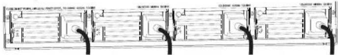
FIG. 2 POWER CORDS MUST BE PLUGGED INTO ALL POWER RECEPTACLES
- Plug the other ends of the power cords into power sources (via surge protector or line conditioner).
- Turn on the power to all and wait until the system status indicator flashes green.
- Check the Indicator LEDs on front and rear of the enclosure; see table below.
- Apply power to endpoints and the source and destination devices.
If indicator lights do not respond with a normal display as stated in the table below, check power connections and see the troubleshooting information in the manual before contacting technical support.
INDICATOR LEDS - NORMAL DISPLAY
| Front Panel POWER – power status Green | ||
| RPS – redundant power supplies Green | ||
| COMM – communication status Reserved for future functionality | ||
| Power Supplies (DC is Tri-color) | AC Power Green | |
| • DC Power• Temperature• Fault status | Green(amber = over temperature;red = fault state) | |
| CPU COMM – communication status Reserved for future functionality | ||
| STATUS Green during boot up(approx. 10 to 30 seconds, depending on load)Blinking green when ready | ||
| Rear Fan Tray Fan speed status Green – Fan RPS within normal range | ||
Establishing Serial Control
The Epica DGX 288 can be controlled by attaching an external control device/system to the serial port (DB-9 connector) or to the USB port* (USB Mini-B connector).
* Controlling the Epica DGX 288 using a USB connection requires the creation of a virtual COM port, which acts as a serial port.
PC Requirements for BCS\*\* via Terminal Emulator:
- Windows 7® or later
- Serial port or USB port
** For information on BCS (Basic Control Structure), a programming language used for programming control operations and for diagnostic purposes, see the Programming Guide – BCS Protocol at www.amx.com.
Serial Port – Serial Control (PCs, AMX control devices, & third-party controllers)
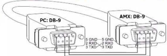
FIG. 3 RS-232 NULL MODEM CABLE PIN DIAGRAM
To establish external serial control from serial port for RS-232:
- Apply power to the Epica DGX 288 (see previous page).
- Plug the null modem cable into the serial port on the enclosure (FIG. 4 and 5).
-
Plug the other end of the cable into the serial port on the serial controller/device.
-
Open the serial communication software and set port settings to match the Epica DGX 288 default settings:
baud rate = 9600, data bits = 8, stop bit = 1, parity = none, flow control = none.
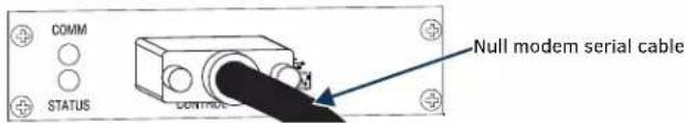
FIG. 4 ATTACH NULL MODEM SERIAL CABLE TO DB-9 SERIAL PORT
To establish external serial control from USB (Mini-B) port:
IMPORTANT: You must have adequate rights for the PC to install a USB driver. Check with your System Administrator to be sure you have the required access.
- Download the APBridge.inf hardware device driver file from www.amx.com.
- Apply power to the Epica DGX 288 (see instructions on previous page).
- Plug one end of the USB cable into the USB (Mini-B) port on the enclosure and the other end to the USB port on the PC.
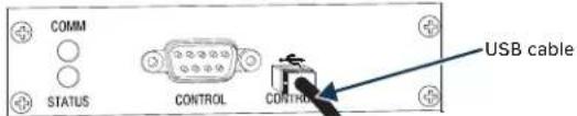
FIG. 5 ATTACH USB CABLE TO USB (MINI-B) PORT
IMPORTANT: You must identify the virtual COM port assigned to the USB connector to enable communication between the control application on the PC and the enclosure.
- Open the Device Manager window (Start/Control Panel/Device Manager), open Other devices and right-click on the Unknown device icon. Select Properties from the menu items. The Unknown device Properties window opens.
The Device Manager may have a different location depending on the operating system and theme selected.
-
In the driver tab, select the Update Driver button.
-
Browse for the APBridge.inf file and select the Next button. Another Update Driver Software window appears. Click Close.
A Windows Security window may open and ask if you wish to install a driver with an unverified publisher. Select the "Install this driver software anyway" option.
- Make note of AutoPatch USB Bridge COM port number in Device Manager window. (If port number doesn't show, right click and check Properties.
This port number will remain the same unless a different USB port is used on the PC or a different device is attached to the PC through this USB port.
- Open the control application.
When establishing communication between the control application on the PC and the Epica DGX 288, be sure to check application's serial port settings and select correct virtual COM port for AutoPatch USB Bridge. Epica DGX 288 default settings are: baud rate = 9600, data bits = 8, stop bit = 1, parity = none, and flow control = none.
Completing the Installation
We recommend completing the installation by executing a test switch routing Input 1 to Output 2. Connect a DXLink Fiber TX to the IN port of Input 1 and a DXLink Fiber RX to the OUT port of Output 2. The method of executing the switch will depend on the control option used. Control options and switching information are provided below.
- BCS Commands (via terminal emulator such as TeraTerm, PuTTY, or HyperTerminal) – When power is applied, a short splash screen appears. Enter c1102T into the terminal emulation program (routes Input 1 to Output 2 on the default level). When c1102T appears, the switch is successful.
- AMX Control Devices – The Epica DGX 288 is compatible with a number of AMX control devices. For control programming information, see the Hardware Reference Manual for the specific device.
The system is now ready to attach the remaining source and destination devices and any applicable DXLink Fiber Transmitters and Receivers.
Basic BCS Commands
☐ To execute a switch:
CL#I#O#T or CL#O#I#T
☐ To disconnect a switch:
DL#I#T or DL#O#T
☐ To verify switch status:
SL#O#T or SL#I#T The result is in ( ), e.g., SL003T(12)
Additional Information in the switcher's Hardware Reference Manual
See the Epica DGX 288 Matrix Switcher Hardware Reference Manual at www.amx.com for information on the following:
• System and board specifications
- APDiagnostics software (monitors/displays advanced diagnostic data)
- Redundant power supplies
- Adding or replacing boards