SD-AT-DK-S - Kategooriata Atdec - Tasuta kasutusjuhend
Leidke seadme juhend tasuta SD-AT-DK-S Atdec PDF-formaadis.

Kasutajate küsimused teemal SD-AT-DK-S Atdec
0 küsimus selle seadme kohta. Vastake nendele, mida teate, või esitage oma.
Esita uus küsimus selle seadme kohta
Laadige alla juhend oma Kategooriata PDF-formaadis tasuta! Leidke oma juhend SD-AT-DK-S - Atdec ja võtke oma elektrooniline seade uuesti kätte. Sellel lehel on avaldatud kõik teie seadme kasutamiseks vajalikud dokumendid. SD-AT-DK-S kaubamärgi Atdec.
KASUTUSJUHEND SD-AT-DK-S Atdec
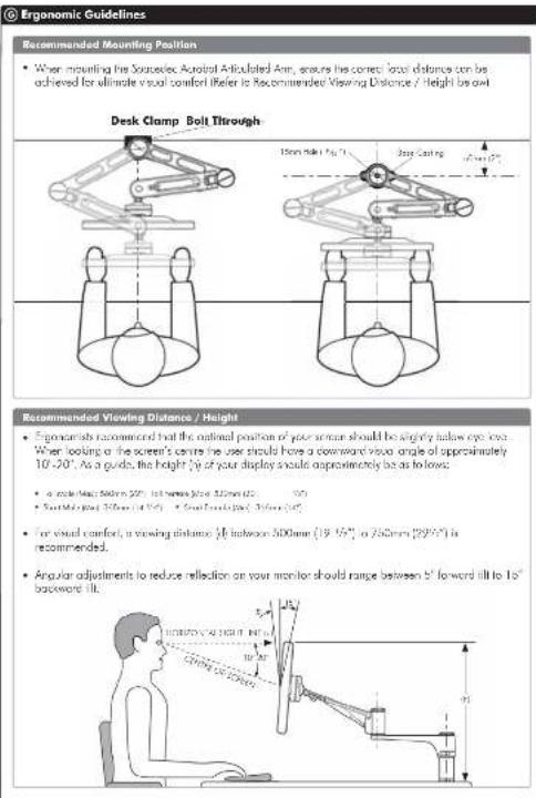
Recommended Mounting Position
- When mounting the Sourcelec Acrotal Articulated Arm, ensures the correct local distance can be achieved for ultimate visual comfort (Refer to Recommended Viewing Distance / Height) by exit
Recommended Viewing Distance / Height
• Exonerists recommended that the optimal position of your screen should be slightly below eye loss. When looking at the screen's centre the user should have a downward view angle of approximately 10°-20°, as a guide, the height of your display should approximately be as to lows:
• a mole (kg) 500m (22") (b) h (mm) (12)
• South Malaysia (31/2007) • South Australia (31/2007)
- For visual comfort, a viewing distance 0 between 300mm ( 19.15^ , 0.756 mm ( 29.05^ ) is recommended.
- Angular adjustments to reduce reflection on your monitor should range between b^ forward till to 10^ backward till.
The Arcobar Articulated Arm comes factory set to support 60 g displcs. Adjust the arm to suit the weight of your display as shown in the following steps:
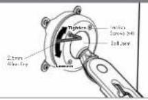
H.1. Adjusting the Ball Joint Resistance
Depending on the weight of the monitor. It may be necessary to make adjustments to the Bull Joint Mechanism. If the monitor doesn't hold its position or is too resistant, adjust the four tension screws located around the Bull Joint (see diagram or the right) using the supplied 2.5mm Alter Key.
Check the display, and then adjust again if necessary.
NOTE: Be sure to adjust screws evenly.
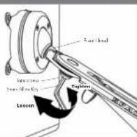
H.2. Adjusting the Pivot Head Resistance
It is possible to control the amount of resistance in the Final I load to suit your display.
To increase the resident of the Pivot Head to suit heavier displays, use the Seven Allan Key supplied in the Desk Clamp Box to tighten the interscrew in a clockwise direction.
To decrease the resistance of the Five lead to still lighter displays, loosen the overscrew in an anti-delta swing; intra-tion.
NOTE: It is recommended the Pivot Head be left at the factory setting for best performance.
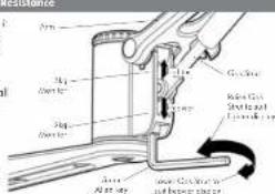
H.3. Adjusting the Articulated Arm/Gas Stret Resistance
H.3.1. Depending on the weight of the meritor, it may be necessary to adjust the arm. This can be done by using the Smer Allen Key supplied in the Desk Clamp Box.
H.3.2. If the arm tends to automatically use or fall when the display is attached, it will be necessary to move small adjustments to the gas shot. Less diagram on the right:
H.3.3. If the arm tends to rise, the gas strut position should be raised. If the arm tends to fall, the gas strut position should be lowered.
H Adjusting the Display
Installation Complete

A) C2001: 1.000000, 1984; 1.000000, 1985; 1.000000, 1986; 1.000000, 1987; 1.000000, 1988; 1.000000, 1989; 1.000000, 1990; 1.000000, 1991; 1.000000, 1992; 1.000000, 1993; 1.000000, 1994; 1.000000, 1995; 1.000000, 1996; 1.000000, 1997; 1.000000, 1998; 1.000000, 1999; 1.000000, 2000; 1.000000, 2001; 1.000000, 2002; 1.000000, 2003; 1.000000, 2004; 1.000000, 2005; 1.000000, 2006; 1.000000, 2007; 1.000000, 2008; 1.000000, 2009; 1.000000, 2010; 1.000000, 2011; 1.000000, 2012; 1.000000, 2013; 1.000000, 2014; 1.000000, 2015; 1.000000, 2016; 1.000000, 2017; 1.

Component Checklist
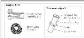
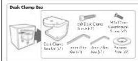
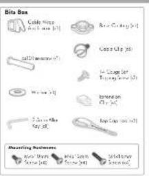
A Component Checklist
Check you have received all parts against the Component Checklist above.
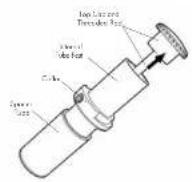
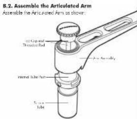
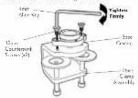
B.1. Disassemble the Tube Assembly In order to attach the Articulated Ann to the tube assembly you will need to remove the Top Cap and Trenandes Rod as shown:
Assembling the Arm
© Mounting Options
There are two Mounting Options: Desk Clamp and Bolt Through
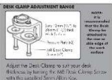
To use the Bolt Through system (Suits desktop thicknesses of 12mm-40mm [1/2"-1/2"] follow the Bolt Through instructions at C.1. To use the Desk Clamp (Suits desktop thicknesses of 12mm-38mm [1/2"-1/2"] follow the Desk Clamp instructions at C.2.
C.1. Bolt Through
C.1.1. Base Casting
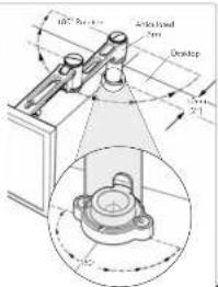
The Arlicatoe Arm is limited to 180° rotation. This is determined by the location of the Base Costing, as shown.
When mounting the Bose Casting, ensure that the Articulated Arm is free to achieve its full 180° range of movement.
Mounting the Base Casting in a 90° corner, position the casting to ensure that the Armstone Arm can only make contact with one side of the corner.
The Base Casting should be mounted no less than 50mm (2") from the edge of the deck.
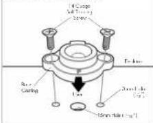
C.1.2. Drill Mounting Hole
Position the Base Costing on the desk in the
desired anchor causing that the letter "p" places the user. Using the base casting position, ocate and mark the holes (e.g.) for drilling.
Drill the roles and then secure the Base Costing to the desk using the supplied 14 George Sell Topping Scenes (12)
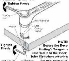
C.1.3. Installing the Articulated Arm
In our 10th reverse way through the help in the work surface.
Using both hands, secure the M'Q Intersome with the 3mm Alen Key and use the other hand to tighten the Thecoded Red into the Intersome with the supplied Top Cool tool.
OR
C.2. Desk Clamp
C.2.1. Assemble Desk Clamp
Place the Base Casting on top of the Desk Clamp using the "F" is facing towards the user. Using the Arm Allen Key, attach the Base Casting to the clamp by inserting the supplied (M2)Arm Courmourie Screws (p/2) into the hoes in the Base Casting as shown.
C.2.2. Attaching the Desk Clamp
Place the Desk Clamp in the desired position on the edge of the cekta and secure in place using the sample: Smm Alkn Kay as shown in diagrams.
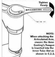
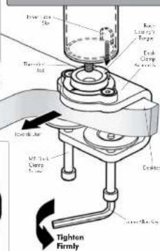
C.2.3. Attaching the Articulated Arm
Use the Top Cop Tool to lighten the Threaded Rod into the Base Casting as shown.
NOTE: Desk Clamp Assembly is Suitable for square edged desks only
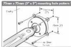
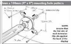
© Attaching the Display
Direct Mount Configuration
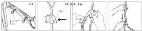
© Installing Cable Management
E.1. Push the four supplied Cable Clips into the holes on the underside or the arm as shown in diagram
E.2. Food the cables into the Cabe Wrap Analyzer
E.3. Insert the Cable Wrap Applicator into the Cable Wrap as shown.
E.4. Source the nose of the Applicator and place inside the Cable Wrap ensuring that the opening edges of the Cable Wrap face towards the nose of the applicator as shown in diagram.
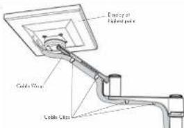
© Attaching the Cable Wrap to the Arm
F.1. Position the display of its highest axial position to ensure that there is sufficient cabling at the end of the arm so the cubies are not stretched or pulled out when the display is moved.
F.2. Clip the cable wrap into the four Cable Clips as shown in diagram.
BEFORE PROCEEDING TO THE NEXT STEP PLEASE NOTE:
DO NOT adjusted tension screws on gas shut until your display has been attached.