MAS36 5 GAS XT - Pliit BERTAZZONI - Tasuta kasutusjuhend
Leidke seadme juhend tasuta MAS36 5 GAS XT BERTAZZONI PDF-formaadis.

Kasutajate küsimused teemal MAS36 5 GAS XT BERTAZZONI
0 küsimus selle seadme kohta. Vastake nendele, mida teate, või esitage oma.
Esita uus küsimus selle seadme kohta
Laadige alla juhend oma Pliit PDF-formaadis tasuta! Leidke oma juhend MAS36 5 GAS XT - BERTAZZONI ja võtke oma elektrooniline seade uuesti kätte. Sellel lehel on avaldatud kõik teie seadme kasutamiseks vajalikud dokumendid. MAS36 5 GAS XT kaubamärgi BERTAZZONI.
KASUTUSJUHEND MAS36 5 GAS XT BERTAZZONI

INSTALLATION, USE & CARE MANUAL
FREESTANDING GAS RANGES
Models
MAS36 5 GAS XTLP
MAS36 5 GAS XELP
[M3W0GNA7X(2,5)AUA]
[M3W0GNA7X(2,5)AUG]

310823

BERTAZZONI SpA
Via Palazzina 8
42016 Guastalla RE
ITALY
WWW.BERTAZZONI-ITALIA.COM
From the desk of the President
Dear new owner of a Bertazzoni product,
I want to thank you for choosing one of our beautiful PRO ranges. We know that you have many brands and products to choose from and we are thrilled that you have decided to take onw of your products into your home.
We take as much pride in making our ranges as we hope you will in owning them. My family started manufacturing cooking appliances in 1882. Each of our products is a blend of Italian design finess and superior appliance technology. While we can not replace your unique talent at cooking delicious recipes for yourself, your family and your friends, we try our best to make cooking easier, more effective and more fun.
Our appliances are designed according to the strictest safety and performance standard for the European and the North American market. We follow the most advanced manufacturing philosophy. Each appliance leaves the factory after thorough quality inspection and testing. Our distributors and our service partners are ready to answer any questions you may have regarding how to install, use and care for your Bertazzoni product.
This manual will help you learn to use the product in the safest and most effective manner and care for it so that it may give you the highest satisfaction for years to come.
The manual also includes directions for the professional installer that will install the product in your home. We recommend using factory-trained professionals for the delicate task of installing and testing appliances in your home. Please call Customer Service at (800) if you need help locating a factory-trained professional installer in your area.
Please keep this manual for future use.
Grazie!

TABLE OF CONTENTS
WARRANTY AND SERVICE......4
CUSTOMER SERVICE....4
REPLACEMENT PARTS 4
IMPORTANT SAFETY INFORMATION ....5
PRODUCT SPECIFICATIONS....6
BEFORE INSTALLATION 7
INSTALLING THE LEGS 8
INSTALLING THE WORKTOP FRONTGUARD 8
INSTALLING THE BACKGUARD....9
ELECTRICAL 10
GAS....10
INSTALLATION ADJACENT TO KITCHEN CABINETS....11
EXHAUST HOOD INSTALLATION 11
ELECTRICAL CONNECTION....12
WIRING DIAGRAM....12
GAS CONNECTION 13
GAS CONNECTION 13
PRESSURE REGULATOR 14
GAS CONVERSION 15
STEP 1: PRESSURE REGULATOR....15
STEP 2: SURFACE BURNERS 16
STEP 3: MAIN OVEN BURNER ....16
STEP 4: BROILER BURNER....17
STEP 6: MINIMUM FLAME ADJUSTMENT....19
INSTALLATION CHECKLLST 21
INSTALLATION CHECKLLST 21
FINAL PREPARATION 21
USER MANUAL 22
ROOM VENTILATION 22
SURFACE BURNER LAYOUT 22
SURFACE COOKING....23
SYMBOLS 23
SURFACE BURNER OPERATION 23
TIPS FOR USING BURNERS CORRECTLY 24
TIPS FOR USING PANS CORRECTLY 24
OVEN COOKING....25
SYMBOLS....25
OVEN SHELVES 26
GAS OVEN OPERATION....26
CONVECTION COOKING 27
COOKING WITH THE GAS BROILER....28
USING THE THERMOMETER 28
MAINTAINING YOUR RANGE....29
REPLACING THE OVEN LIGHT BULB 29
COOLING FAN FAILURE....29
CLEANING YOUR RANGE....29
IMPORTANT APPLIANCE INFORMATION .... 31
WARRANTY AND SERVICE
All Bertazzoni products carry a 2 year parts and labor warranty.
Service on all Bertazzoni products shall be carried out by factory-trained professionals only.
For warranty service please contact Customer Service at the numbers indicated below.
CUSTOMER SERVICE
English/spanish hotline (866) 905-0010
French (800) 561-7625
Fax (7142)8-0040
BERTAZZONIHELP@SERVICEPOWER.COM
Mailing address
SERVICEPOWER
1503 South Coast drive
Suite 320
Costa Mesa CA 92626
REPLACEMENT PARTS
Only Bertazzoni replacement parts may be used in performing service on the appliance.
Replacement parts are available from factory authorized parts distributors.
AP Wagner PHONE 716 961 7131 FAX 716 856 4779
Reliable Parts PHONE 206 5758818 FAX 206 5750910
Coast PHONE 800 821 0244 FAX 604 321 6646
IMPORTANT SAFETY INFORMATION
PLEASE READ AND FOLLOW THESE IMPORTANT INSTRUCTIONS FOR THE SAFETY OF YOUR HOME AND OF THE PEOPLE LIVING IN IT.
Save this Manual for local electrical inspector's use.
Read and save these instructions for future reference.
Observe all governing codes, ordinances and regulations.
WARNING!
If the information in this manual is not followed exactly, a fire or explosion may result causing property damage, personal injury or death.
Do not store or use gasoline or other flammable substances in the vicinity of this or any other appliance.
Installation and service must be performed by a qualified installer, service agency or the gas supplier.
In Massachusetts: All gas products must be installed by a "Massachusetts" licensed plumber or gasfitter. A "T" handle type manual gas valve must be installed in the gas line connected to this appliance.
WHAT TO DO IF YOU SMELL GAS
- Do not light any appliance.
- Do not touch any electrical switch.
- Do not use any phone in your building.
- Immediately call your gas supplier from a neighbor's phone. Follow the gas supplier's instructions.
- If you cannot reach your gas suppliers, call the fire department.

WARNING
NEVER use this appliance as a space heater to heat or warm the room. Doing so may result in carbon monoxide poisoning and overheating of the oven
Warning!
This range can tip. Injury to persons could result. Install anti-tip device shipped with range. See Installation Instructions.
WARNING!
Read this instruction booklet before installing and using the appliance.
The manufacturer will not be responsible for any damage to property or to persons caused by incorrect installation or improper use of the appliance.
The manufacturer reserves the right to make changes to its products when considered necessary and useful, without affecting the essential safety and operating characteristics.
This appliance has been designed for non-professional, domestic use only.
Do not use this appliance to heat a room.
Do not place any pot or pan on the open oven door. The door is made of glass and it can break if loaded with a weight.
Before beginning installation, please read these instructions completely and carefully.
Do not remove permanently affixed labels, warnings, or plates from the product. This may void the warranty. -Please observe all local and national codes and ordinances.
Please ensure the range is properly grounded.
The installer should leave these instructions with the consumer who should retain for local inspector's use and for future reference.
The plug should always be accessible.
Installation must conform with local codes or in the absence of codes, the National Fuel Gas Code NSIZ223.1-latest edition. Electrical installation must be in accordance with the National Electrical Code, ANIS/NFPA70 - latest edition and/or local codes. IN CANADA: Installation must be in accordance with the current CAN/CGA-B149.1 National Gas Installation Code or CAN/CGA-B 149.2, Propane Installation Code and/or local codes. Electrical installation must be in accordance with the current CSA C22.1 Canadian Electrical Codes Part 1 and/or local codes.
Installation of any gas-fired equipment should be made by a licensed plumber. A manual gas shut-off valve must be installed in the gas supply line ahead of the oven in the gas flow for safety and ease of service.
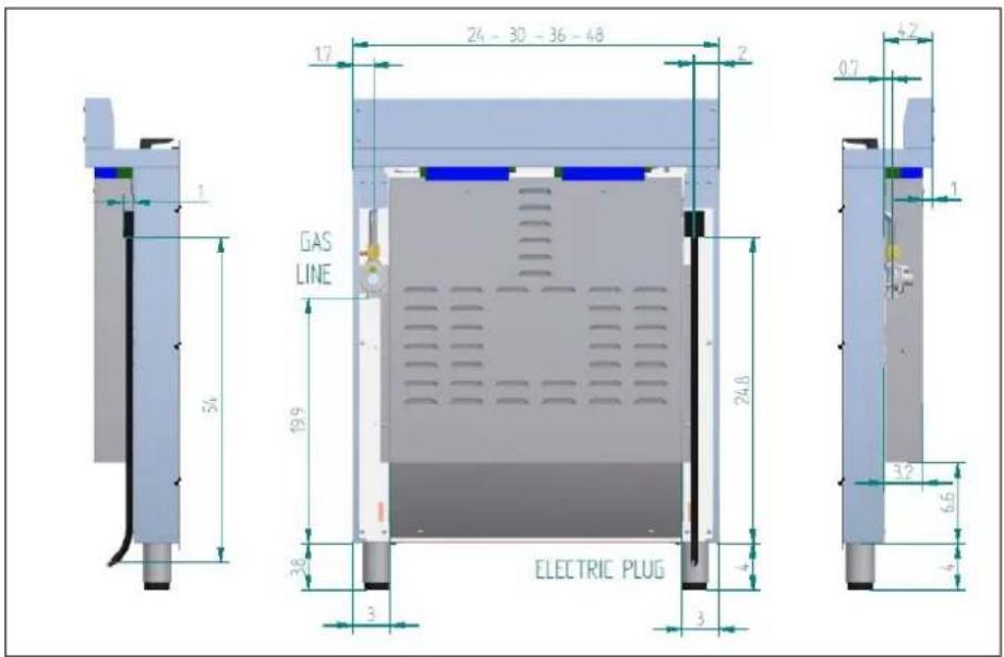
PRODUCT SPECIFICATIONS
Dimensions (insert drawings front, side and back
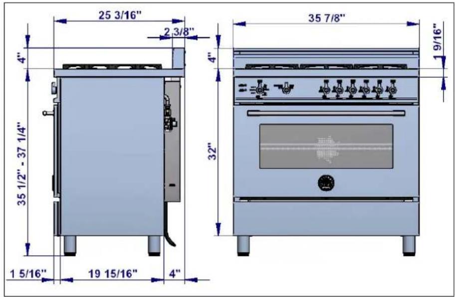
Weight
Burner power
| Natural gas | LP gas | |
| Auxiliary | 3750 BTU/h | 3750 BTU/h |
| Semi-rapid | 6000 BTU/h | 6300 BTU/h |
| Rapid | 10400 BTU/h | 11400 BTU/h |
| Dual burner (inner) | 2730 BTU/h | 2900 BTU/h |
| Dual burner ( outer) | 15000 BTU/h | 16400 BTU/h |
| Oven | 16000 BTU/h | 16000 BTU/h |
| broiler | 14500 BTU/h | 14500 BTU/h |
BEFORE INSTALLATION
This appliance shall only be installed by an authorized professional.
This appliance shall be installed in accordance with the manufacturer's installation instructions.
This appliance must be installed in accordance with the norms & standards of the country where it will be installed. The installation of this appliance must conform to local codes and ordinances. In the absence of local codes, Installations must conforms to American National Standards, National Fuel Gas Code ANSI Z223.1 – latest edition** or B149.1.
The appliance, when installed, must be electrically grounded in accordance with local codes or, in the absence of local codes, with the National Electrical Code, ANSI/NFPA 70.
If local codes permit, a flexible metal appliance connection with the new AGA or CGA certified design, max. 5 feet (1,5 m) long, 12 I.D. is recommended for connecting this appliance to the gas supply line. Do not bend or damage the flexible connector when moving the appliance.
This appliance must be used with the pressure regulator provided. The regulator shall be properly installed in order to be accessible when the appliance is installed in its final location. The pressure regulator must be set for the type of gas to be used. The pressure regulator has 12 " female pipe thread. The appropriate fitting must be determined based on the size of your gas supply line, the flexible metal connector and the shutoff valve.
The appliance must be isolated from the gas supply piping system by closing its individual manual shutoff valve during any pressure testing of the gas supply piping system at test pressures equal to or less than 12 psi (3.5 kPa).
All opening and holes in the wall and floor, back and under the appliance shall be sealed before installation of the appliance.
A manual valve shall be installed in an accessible location in the gas line external to the appliance for the purpose of turning on or shutting off gas to the appliance
WARNING!
Do not use aerosol sprays in the vicinity of this appliance while it is in operation
ROOM VENTILATION: An exhaust fan may be used with the appliance; in each case it shall be installed in conformity with the appropriate national and local standards. Exhaust hood operation may affect other vented appliances; in each case it shall be installed in conformity with the appropriate national and local standards.
TYPE OF GAS
This appliance is shipped from the factory for use with naturagas. For use with propane lp gas please follow the conversion procedure described on pg. 17. A step by step conversion procedure is also included with each set of lp gas nozzles.
GAS PRESSURE
The maximum inlet gas supply pressure incoming to the gas appliance pressure regulator is 20" water column (5 kPa).
The minimum gas supply pressure for checking the regulator setting shall be at least 1" w.c. (249 Pa) above the inlet specified manifold pressure to the appliance (this operating pressure is 11" w.c. (2.75 kPa) for LP Gas and 4" w.c. (1.00 kPa) for Natural Gas.
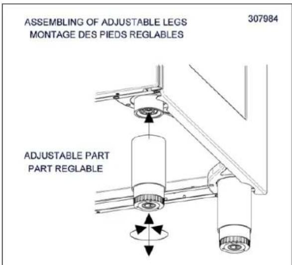
INSTALLING THE LEGS
Bertazzoni ranges must be used only with the legs properly installed.
Four height-adjustable legs are shipped with the range in the polysterene container situated over the appliance.
Before installing the legs, position the appliance near its final location as the legs are not suitable for moving the appliance over long distances.
After unpacking the range, raise it enough to insert the legs in the appropriate receptacles situated on the lower part of the appliance. Lower the range gently to keep any undue strain from legs and mounting hardware. If possible use a pallet or lift jack instead of tilting the unit.
Adjust leg height to the desired level by twisting the inside portion of the leg assembly until the proper height is reached. Check with a level that the cooktop is perfectly level.
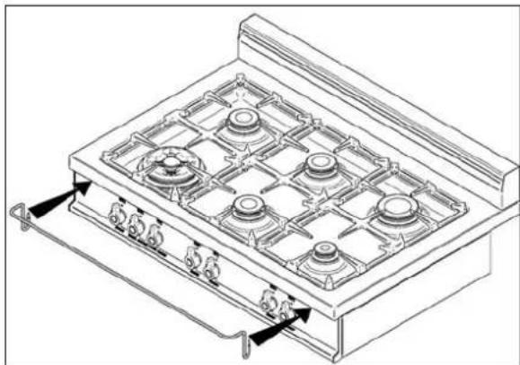
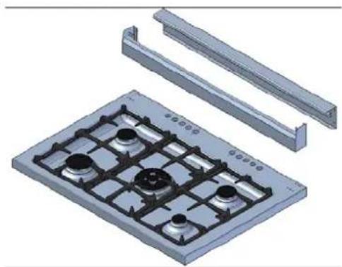
INSTALLING THE WORKTOP FRONTGUARD
To increase the clearance between the front edge of the worktop and the burners it is possible to install the worktop frontguard shipped with the appliance.
To install the front guard, hold it with the pointed edges looking up. Align the edges of the frontguard with the appropriate receptacles in the bottom of the worktop and press firmly until the frontguard is securely attached to the worktop.
ATTENTION: once installed the frontguard may only be removed by disassembling the worktop. Attempting to remove the frontguard without disassembling the worktop will result in permanent damage to the worktop.
natural_image
Line drawing of a gas stove with six fans and heat exchangers (no text or symbols)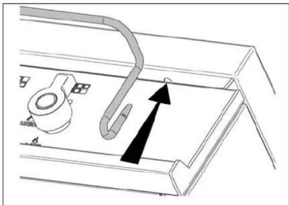
natural_image
Technical diagram of a mechanical component with a curved pipe and directional arrow, no readable text or symbols present.INSTALLING THE BACKGUARD
The backguard must be installed prior to operation of the appliance for appropriate ventilation of the oven compartment.
The supplied backguard is a 2-part assembly. The box also contains a set of metal screws for securing the backguard to the worktop.
natural_image
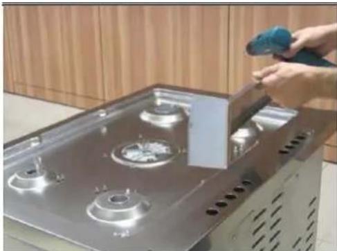
3D rendering of a metal heating element with grid and mounting holes (no text or symbols)Disassemble the backguard and position the front part on the worktop. Align the screw holes with the corresponding holes at the back of the worktop.
natural_image
Hand cleaning a stainless steel gas stove with a blue tool (no text or symbols visible)If the holes are not aligned, partially loosen the brackets att the back of the worktop as shown below.
natural_image
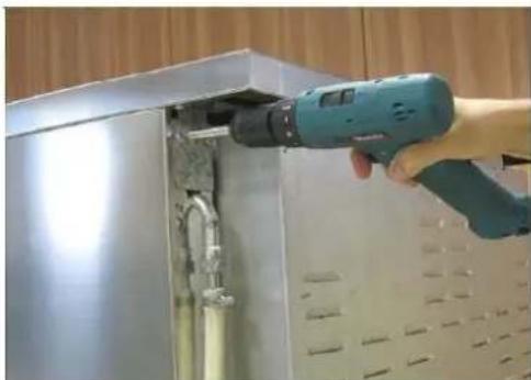
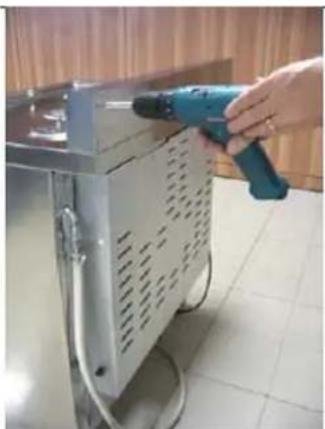
Hand using a power drill to clean or install an open stainless steel cabinet (no text or symbols visible)Install the front part of the backguard by tightening the 2 central screws from the top and
2 lateral screws from the bottom.
natural_image
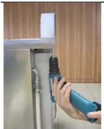
Hand holding a blue electric drill bit next to a metal frame, with wooden paneling in the background (no text or symbols visible)Position the back part of the backguard and secure it to the worktop tightening 4 screws from the bottom.
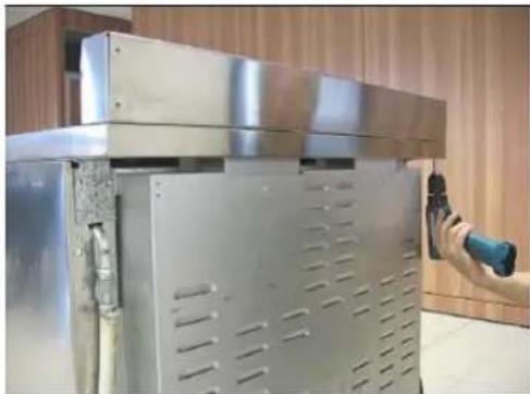
natural_image
Close-up of a stainless steel industrial machine with ventilation grilles and a hand holding a handheld device (no visible text or symbols)Connect the back and front part of the upstand. Check for tight assembly.
natural_image
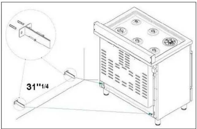
Hand using a power tool to clean or operate a metal electrical cabinet with ventilation grilles (no visible text or symbols)INSTALLING THE ANTI-TIP STABILITY DEVICE
The anti-tip bracket shipped with the range must be properly secured to the rear wall as shown in the pirture below.
The height of the bracket from the floor must be determined after the range legs have been adjusted to the desired height and after the range has been leveled.
Measure the distance from the floor to the bottom of the anti-tip bracket receptacle on the back of the appliance.
Position the two anti-tip brackets on the wall at the desired height plus 1/8" (0.32 cm). The brackets must be placed at 2"5/16 (6,0 cm) from the side of the range. The distance between the two bracket is 31"1/4 (79.3 cm).
Secure the brackets to the wall with appropriate hardware.
Slide the range against the wall until the brackets are fully inserted into their receptacles on the back of the range.
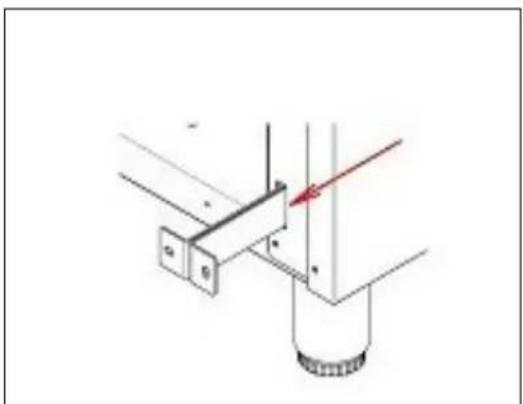
natural_image
Technical diagram showing a mechanical assembly with a bracket and cylindrical component, no visible text or symbolsINSTALLATION REQUIREMENTS
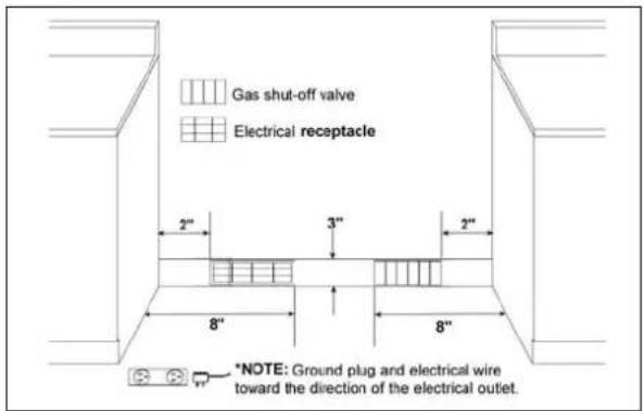
ELECTRICAL
A properly-grounded horizontally- mounted electrical receptacle should be installed no higher than 3" (7.6 cm) above the floor, no less than 2" (5 cm) and no more than 8" (20,3 cm) from the left side (facing product).
Check all local code requirements.
GAS
An agency-approved, properly-sized manual shut-off valve should be installed no higher than 3" (7.6 cm) above the floor and no less than 2" (5 cm) and no more than 8" (20.3 cm) from the right side (facing product).
To connect gas between shut-off valve and regulator, use agency-approved, properly sized flexible or rigid pipe. Check all local code requirements.
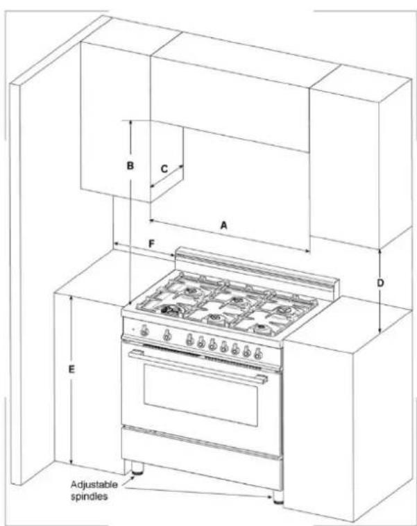
INSTALLATION ADJACENT TO KITCHEN CABINETS
This range may be installed directly adjacent to existing countertop high cabinets (36" or 91.5 cm from the floor).
For the best look, the worktop should be level with the cabinet countertop. This can be accomplished by raising the unit using the adjustment spindles on the legs.
ATTENTION: the range CANNOT be installed directly adjacent to kitchen walls, tall cabinets, tall appliances, or other vertical surfaces above 36" (91.4 cm) high. The minimum side clearance in such cases is 6" (15.2 cm).
Wall cabinets with minimum side clearance must be installed 18" (45.7 cm) above the countertop with countertop height between 35 ½" (90.2 cm) and 37 ¼" (94.6 cm). The maximum depth of wall cabinets above the range shall be 13" (33.0 cm)
| A 36" (91,5 cm) |
| B 36" (91,5 cm) |
| C 13" (33,0 cm) |
| D 18" (45,7 cm) |
| E 35"1/2(90,2 cm) / 37" 1⁄4 (94,6 cm) |
| F 6" (15,2 cm) |
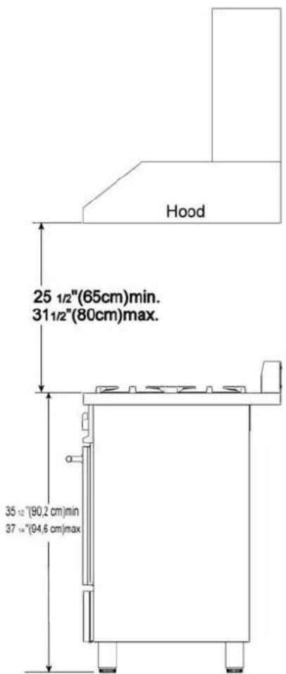
EXHAUST HOOD INSTALLATION
This range will best perform when used with PRO line Bertazzoni exhaust hoods. These hoods have been designed to work in conjunction with the Bertazzoni range and have the same finish for a perfect look.
For maximum performance, the height of the bottom of the hood from the worktop should be between 25 1/2" (65 cm) and 31 1/2" (80 cm). This would typically result in the bottom of the hood being 61 1/2" (156.2 cm) to 67 1/2" (171.5 cm) above the floor. These measurements provide for safe and efficient operation of the hood.
Before installation of the exhaust hood, consult local or regional building and installation codes for additional specific clearance requirements.
Refer to the range hood installation instructions provided by the manufacturer for additional information.
ELECTRICAL CONNECTION
This unit is manufactured for all polarized, grounded 120 volt/60 Hz, 16 amp system.
Electric power consumption is about 300 W.
The minimum of 102 VAC is required for proper operation of gas ignition systems.
The circuit must be grounded and properly polarized.
The unit is equipped with a SJT power cord. In case of replacement, the power cord shall be replaced with one of the same type, size and length.
ELECTRICAL GROUNDING
This appliance is equipped with a three-prong plug for your protection against shock hazard and should be plugged directly into a properly grounded socket. Do not cut or remove the grounding prong from this plug.
□
□□
WARNING!!
ELECTRICAL SHOCK HAZARD
Disconnect electrical power at the circuit breaker box or fuse box before installing the appliance.
Provide appropriate ground for the appliance.
Use copper conductors only.
Failure to follow these instructions could result in serious injury or death
□
CAUTION
Label all wires prior to disconnecting when
servicing controls. Wiring errors can cause improper and dangerous operation.
Verify proper operation after servicing.
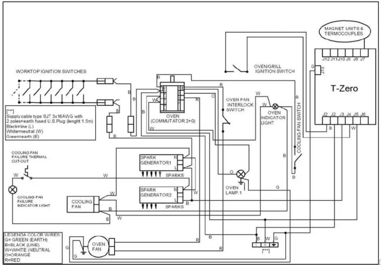
WIRING DIAGRAM
flowchart
graph TD
    A["WORKTOP IGNITION SWITCHES"] --> B["Supply cable type SJT 3x16AWG with 2 poles+earth fused U.S.Plug (length 1.5m)"]
    B --> C["Black=line (L)"]
    C --> D["White=neutral (W)"]
    D --> E["Green=earth (E)"]
    F["COOLING FAN"] --> G["Failure Thermal Cut-OUT"]
    H["COOLING FAN"] --> I["Failure Indicator Light"]
    J["SPARK GENERATOR1"] --> K["SPARK GENERATOR2"]
    L["SPARK GENERATOR2"] --> M["SPARKS"]
    N["OVEN"] --> O["COMMUTATOR 2+0"]
    P["OVEN"] --> Q["INTERLOCK SWITCH"]
    R["OVEN"] --> S["LAMP.1"]
    T["MAGNET UNITS & TERMOCOUPLES"] --> U["T-Zero"]
    V["G"] --> W["B"]
    X["G"] --> Y["B"]
    Z["G"] --> AA["B"]
    AB["G"] --> AC["B"]
    AD["G"] --> AE["B"]
    AF["G"] --> AG["B"]
    AH["G"] --> AI["B"]
    AJ["G"] --> AK["B"]
    AL["G"] --> AM["B"]
    AN["G"] --> AO["B"]
    AP["G"] --> AQ["B"]
    AR["G"] --> AS["B"]
    AT["G"] --> AU["B"]
    AV["G"] --> AW["B"]
    AX["G"] --> AY["B"]
    AZ["G"] --> BA["B"]
    BB["G"] --> BC["B"]
    BD["G"] --> BE["B"]
    BF["G"] --> BG["B"]
    BH["G"] --> BI["B"]
    BJ["G"] --> BK["B"]
    BL["G"] --> BL["B"]
    BM["G"] --> BN["B"]
    BO["G"] --> BP["B"]
    BZ["G"] --> CA["B"]
    CB["G"] --> CC["B"]
    CD["G"] --> CE["B"]
    CF["G"] --> CG["B"]
    CH["G"] --> CI["B"]
    CJ["G"] --> CK["B"]
    CL["G"] --> CM["B"]
    CN["G"] --> CO["B"]
    CP["G"] --> CS["B"]
    CT["G"] --> CU["B"]
    CV["G"] --> CW["B"]
    CX["G"] --> CY["B"]
    CZ["G"] --> DA["B"]
    DB["G"] --> DC["B"]
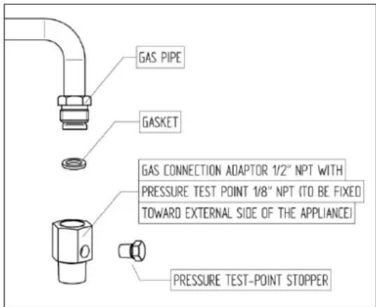
GAS CONNECTION
All gas connections must comply with national and local codes. The gas supply line (service) must be the same size or greater than the inlet line of the appliance. This range uses a 1/2" NPT inlet (see drawing below for details of gas connection). On all pipe joints use appropriate sealant resistant to gas.
This range can be used with Natural or LP/Propane gas. The range is shipped from the factory for use with LP /Propane gas.
For Natural household installation, the appliance must be converted by the dealer, by a factory-trained professional or by a qualified licensed plumber or gas service company.
Gas conversion is important for safe and effective use of the appliance. It is the responsibility of the dealer and the owner of the range to perform the appropriate gas conversion following the directions of the manufacturer.
THE GAS CONVERSION PROCEDURE IS DESCRIBED IN THIS MANUAL AND IN THE PACKAGE CONTAINING THE CONVERSION NOZZLES SHIPPED WITH EVERY RANGE.
Please provide the service person with this manual before work is started on the range.
WARNING!
DO NOT USE AN OPEN FLAME WHEN CHECKING FOR LEAKS!
Leak testing of the appliance shall be conducted according to the manufacturer's instructions. Before placing the oven into operation, always check for leaks with soapy water solution or other acceptable method.
MANUAL SHUT-OFF VALVE
THIS VALVE IS NOT SHIPPED WITH THE APPLICAN AND MUST BE SUPPLIED BY THE INSTALLER.
The manual shut-off valve must be installed in the gas service line between the gas hook-up on the wall and the appliance inlet, in a position where it can be reached quickly in the event of an emergency.
In Massachusetts: A 'T' handle type manual gas valve must be installed in the gas supply line to this appliance.
FLEXIBLE CONNECTIONS
In case of installation with flexible couplings and/or quick-disconnect fittings, the installer must use a heavy-duty, AGA design-certified commercial flexible connector of at least 1/2" (1.3 cm) ID NPT (with suitable strain reliefs) in compliance with ANSI Z21.41 and Z21.69 standards.
In Massachusetts: The unit must be installed with a 36" (3-foot) long flexible gas connector.
In Canada: use CAN 1-6.10-88 metal connectors for gas appliances and CAN 1-6.9 M79 quick disconnect device for use with gas fuel.
PRESSURE TEST-POINT STOPPER VALVE
To avoid gas leaks, the pressure test-point stopper valve and gasket supplied with the range must be installed on the gas fitting at the back of the range according to the diagram below.
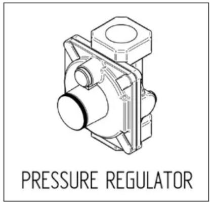
PRESSURE REGULATOR
Since service pressure may fluctuate with local demand, every gas cooking appliance must be equipped with a pressure regulator on the incoming service line for safe and efficient operation.
The pressure regulator shipped with the appliance has has two female threads 12 " NPT. The regulator shall be installed properly in order to be accessible when the appliance is installed in its final position.
Manifold pressure should be checked with a manometer and comply with the values indicated below:
Natural gas → 4.0" W.c.P.
LP/Propane → 11.0" W.C.P.
Incoming line pressure upstream from the regulator must be 1" W.c.P. higher than the manifold pressure in order to check the regulator.
The regulator used on this range can withstand a maximum input pressure of 1/2 PSI (14.0" W.c.P.) If the line pressure exceeds that amount, a step-down regulator is required.
The appliance, its individual shut-off valve, and the pressure regulator must be disconnected from the gas line during any pressure testing of that systemat pressures in excess of 1/2 psig (3.45 kPa).
The individual manual shut-off valve must be in the OFF position during any pressure testing of the gas supply piping system at test pressures equal to or less than 12 psig (3.45 kPa).
GAS CONVERSION
WARNING!
Before carrying out this operation, disconnect the appliance from gas and electricity.
Gas conversion shall be conducted by a factory-trained professional.
Call the customer service hotline to identify a factory-trained professional near your home.
The gas conversion procedure for this range includes 6 steps:
- Pressure regulator
- Surface burners
- Main oven burner
- Broiler burner
- Visual checks prior to closure of oven bottom panel
- Adjustment of minimum setting
The conversion is not completed if all 6 steps have not been concluded properly.
Before performing the gas conversion, locate the package containing the replacement nozzle shipped with every range. IMPORTANT: Each nozzle has a number indicating its flow diameter printed on the body. Consult the table on page 20 for matching nozzles to burners.
Save the nozzles removed from the range for future use.
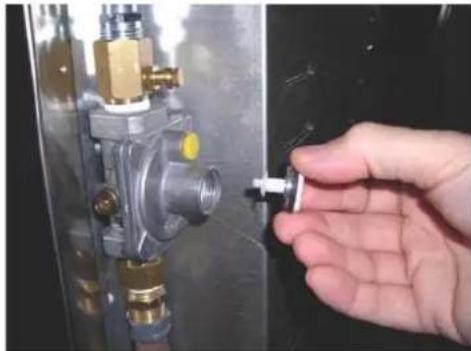
STEP 1: PRESSURE REGULATOR
The pressure regulator supplied with the appliance is a convertible type pressure regulator for use with LP/Propane Gas at a nominal outlet pressure of 11" w.c. or Natural gas at a nominal outlet pressure of 4" w.c. and it is pre-arranged from the factory to operate with one of these gas/pressure as indicated in the labels affixed on the appliance, package and Instruction booklet.
To convert the regulator for use with other natural gas:
- Unscrew by hand the upper cap of the regulator, remove the white plastic attachment from the cap, reverse its direction and screw it again firmly against the cap. The white plastic attachment has arrows indicating the position for LP gas (LP) and natural gas (NAT).
- Screw by hand the metal cap in the original position on the regulator.
natural_image
Hand inserting a small metallic component into a pressure vessel (no text or symbols visible)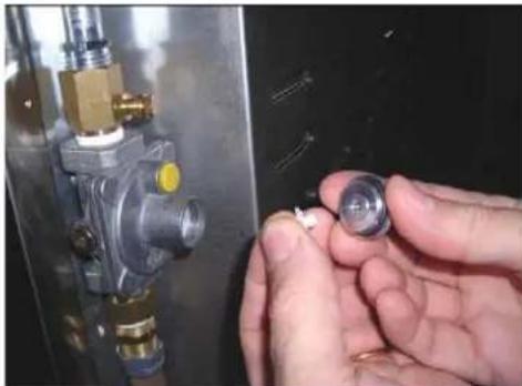
natural_image
Close-up of hands holding a small metallic component next to a metallic valve or pressure vessel (no visible text or symbols)STEP 2: SURFACE BURNERS
To replace the nozzles of the surface burners, lift up the burners and unscrew the nozzles shipped with the range using a 7 mm (sochet wrench).
Replace nozzles using the conversion set supplied with the range or by a Bertazzoni authorized parts warehouse. Each nozzle has a number indicating its flow diameter printed on the body. Consult the table on page 20 for matching nozzles to burners.
natural_image
Interior view of a circular mechanical component with internal cavities and mounting holes (no text or symbols visible)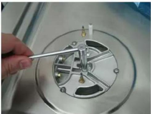
natural_image
Close-up of a hand using a tool to adjust or install a mechanical component on a circular metallic base (no visible text or symbols)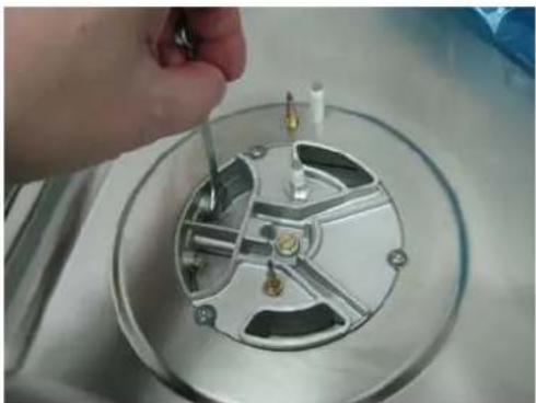
natural_image
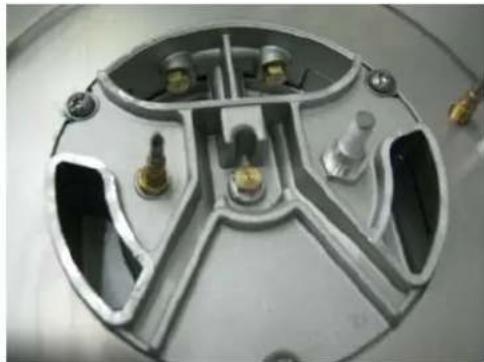
Close-up of a hand using a tool to adjust or install a mechanical component, no visible text or symbolsSTEP 3: MAIN OVEN BURNER
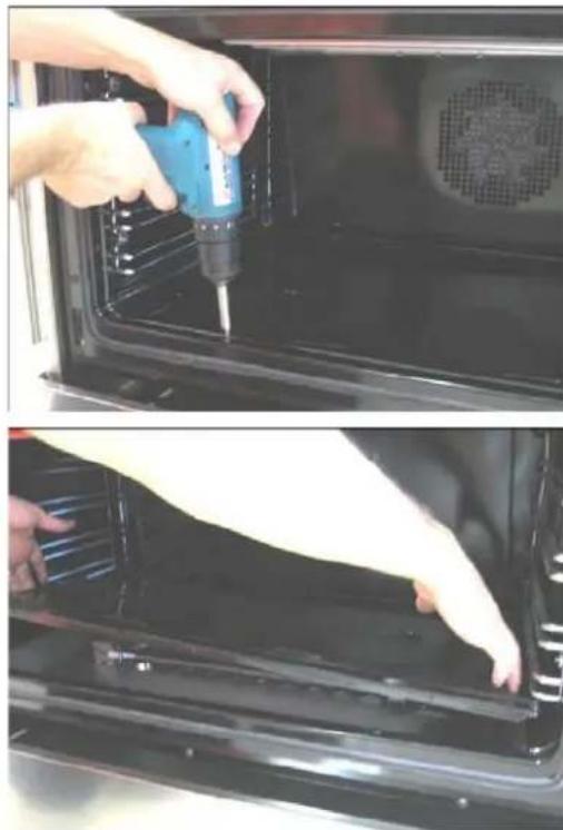
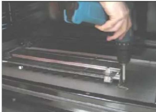
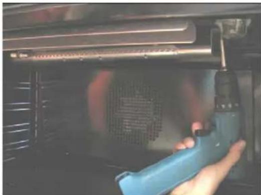
To replace the nozzles of the main oven burner, start by removing the bottom panel of the oven.
natural_image
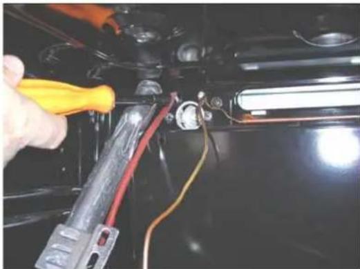
Two-panel photo showing hands using a power tool to clean or install an oven; no text or symbols visible.Loosen the screw located on the right side of the burner and pull out the burner from its support.
ATTENTION: pay extra attention to avoid damage to the igniter and thermocouple.
natural_image
Close-up of a hand operating a 3D printer to press or install a physical component (no visible text or symbols)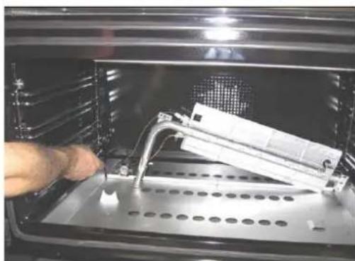
natural_image
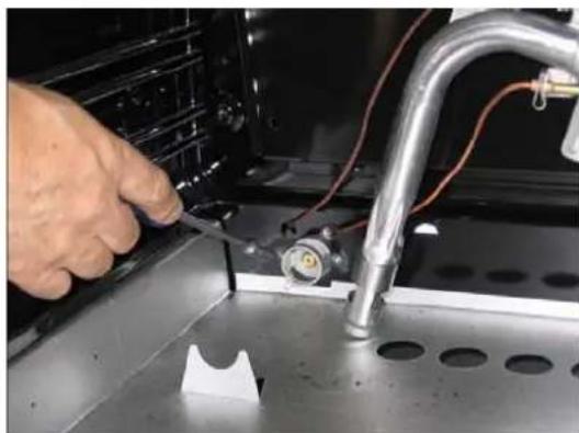
Close-up of a hand inserting a plastic component into an open industrial oven (no visible text or symbols)Unscrew the nozzle located inside the gas fitting using a 10 mm [ socket wrench].
Replace the nozzle using the conversion set supplied with the range or by a Bertazzoni authorized parts warehouse. Each nozzle has a number indicating its flow diameter printed on the body. Consult the table on page 20 for matching nozzles to burners.
natural_image
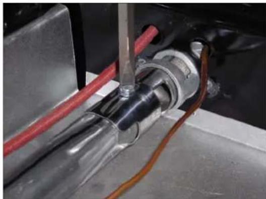
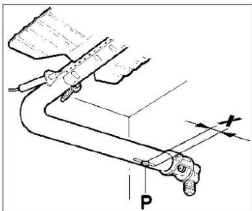
Close-up of a hand using a tool to adjust or install electronic components on a metal panel (no visible text or symbols)Adjust the primary airflow by loosening the screw P and setting the gap X in the Venturi cone to 12 " (5/16" for natural gas).
natural_image
Close-up of a mechanical assembly with metallic components and wiring (no visible text or symbols)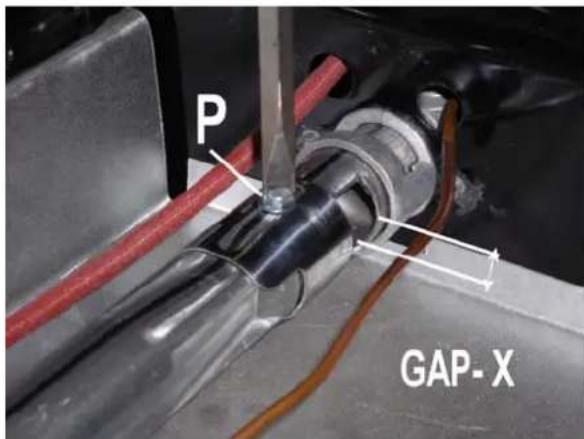
STEP 4: BROILER BURNER
Loosen the screw and pull out the burner from its support.
ATTENTION: pay extra attention to avoid damage to the igniter and thermocouple.
natural_image
Person using a handheld tool to clean or install a metal tray inside an oven (no visible text or symbols)Using a 7 mm [name of the tool] unscrew the nozzle. Replace the nozzle using the conversion set supplied with the range or by a Bertazzoni authorized parts warehouse. Each nozzle has a number indicating its flow diameter printed on the body. Consult the table on page 20 for matching nozzles to burners.
natural_image
Close-up of a hand using a power tool to adjust or install components on a black electrical panel (no visible text or symbols)Adjust the gap X by setting it to fully open position.
STEP 5: VISUAL CHECKS
Before reinstalling the bottom panel, the following visual check must be performed to ensure that the conversion has been carried out properly and without damage to other components of the range.
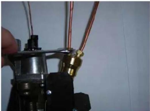
A) CONNECTION OF THERMOCOUPLES TO THERMOSTAT
The thermocouples for both broiler and main oven burner are connected to the same magnet. Tight gently the two connections alternating action on the two nuts. Do not fully tighten one thermocouple before having started to tighten the second one.
natural_image
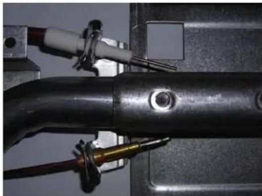
Close-up of a mechanical assembly with copper wires and a brass connector (no visible text or symbols)B) OVEN IGNITER AND THERMOCOUPLE POSITION
The appropriate gap between the tip of the spark plug or thermocouple and the burner shall be approximately 1/8".
natural_image
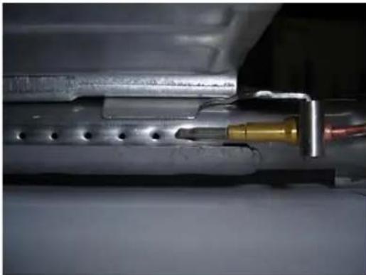
Close-up of a metallic pipe with attached wiring and fittings, no visible text or symbolsThe tip of the spark plug or thermocouple must fully overlap at least the first gas emission hole of the burner.
natural_image
Close-up of a mechanical assembly with a yellow component inserted into a pipe, no visible text or symbolsAfter performing all these visual checks, reinstall the bottom panel of the oven compartment and proceed to setting the minimum for each burner.
STEP 6: MINIMUM FLAME ADJUSTMENT
WARNING!
These adjustments should be made only for use of the appliance with natural gas. For use with liquid propane gas, the choke screw must be fully turned in a clockwise direction.
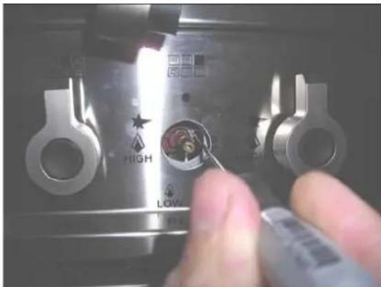
SURFACE BURNERS
-
Light one burner at a time and set the knob to the MINIMUM position (small flame).
-
Remove the knob.
-
The range is equipped with a safety valve. Using a small-size slotted screwdriver, locate the choke valve on the valve body and turn the choke screw to the right or left until the burner flame is adjusted to desired minimum.
-
Make sure that the flame does not go out when switching quickly from the MAXIMUM to the MINIMUM position.
natural_image
Close-up of a hand using a tool to adjust a metal component with 'HIGH' and 'LOW' labels (no readable text beyond symbols)OVEN BURNER
- Set the oven temperature control knob to the MAXIMUM setting.
- Close the oven door and operate the oven for at least 10 minutes.
- Set the knob to the MINIMUM setting
- Remove the knob.
- With a slotted screwdriver turn the choking screw (by-pass screw at the left side of the thermostat bar) and, while observing the flame at the same time through the bottom oven porthole, evaluate the consistency of the flame so it remains on when switching quickly from MINIMUM to MAXIMUM setting.
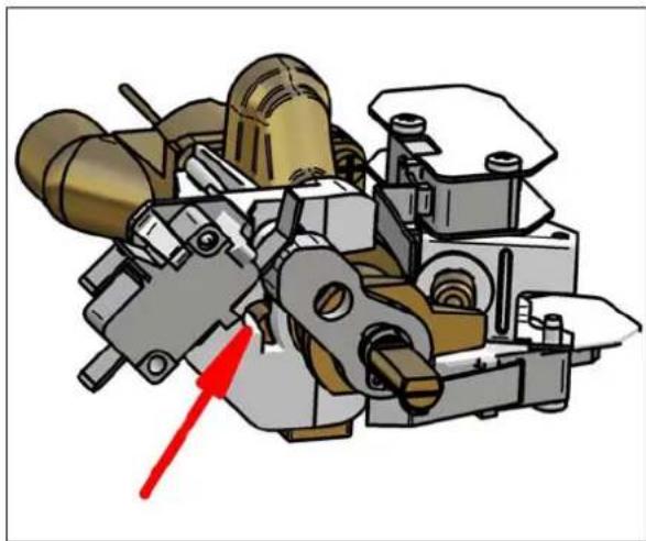
natural_image
Mechanical assembly diagram showing internal components with a red arrow pointing to a specific part (no text or labels present)Broiler burner: the broiler burner always operates at maximum, therefore no minimum adjustment is required.
Models
MAS36 5 GAS XTLP
MAS36 5 GAS XELP
[M3W0GNA7X(2,5)AUA]
[M3W0GNA7X(2,5)AUG]
| Burner | Position | Injector | Gas | Pressure | Max Rate | Min Rate | By-pass | ||
| diam. [mm.] | Type | [i.w.c.] | [BTU/h] | [W] | [BTU/h] | [W] | diam. [mm] | ||
| Auxiliary | Front R | 0,92 | NG | 4" | 3750 | 1098 | 900 | 264 | Regulated |
| 0,56 | LP (Propane) | 11" | 3750 | 1098 | 900 | 264 | 0,29 | ||
| Semi-Rapid | Rear L and R | 1,17 | NG | 4" | 6000 | 1759 | 1500 | 439 | Regulated |
| 0,73 | LP (Propane) | 11" | 6300 | 1845 | 1500 | 439 | 0,36 | ||
| Rapid | Front L | 1,55 | NG | 4" | 10400 | 3046 | 2500 | 732 | Regulated |
| 0,98 | LP (Propane) | 11" | 11400 | 3339 | 2500 | 732 | 0,47 | ||
| Dual Burner | Centre Inner | 0,80 | NG | 4" | 2730 | 799 | 900 | 264 | Regulated |
| 0,50 | LP (Propane) | 11" | 2900 | 849 | 900 | 264 | 0,29 | ||
| Centre Outer | N°2 x 1,30 | NG | 4" | 15000 | 4394 | 4500 | 1318 | Regulated | |
| N°2 x 0,83 | LP (Propane) | 11" | 16400 | 4804 | 4500 | 1318 | 0,65 | ||
| Oven | Oven downside | 2,00 | NG | 4" | 16000 | 4688 | 4000 | 1172 | Regulated |
| 1,15 | LP (Propane) | 11" | 16000 | 4688 | 4000 | 1172 | 0,60 | ||
| Broiler | Oven upside | 1,90 | NG | 4" | 14500 | 4248 | Only Max | Only Max | No by-pass |
| 1,10 | LP (Propane) | 11" | 14500 | 4248 | Only Max | Only Max | No by-pass | ||
INSTALLATION CHECKLIST
- Is the range mounted on its legs?
- Is the backguard securely connected?
- Has the anti-tip device been properly installed?
- Does the clearance from the side cabinets comply with the manufacturers directions?
- Is the electricity properly grounded?
- Is the gas service line connected following the directions of the manufacturer?
- Have all the proper valves, stoppers and gasket been installed between the range and the service line?
- Has the gas connection been checked for leaks?
- Has the range been set for the type of gas available in the household?
- Is the ignition of all oven burners functioning properly?
- Is the air flow to the over and broiler burners properly adjusted?
- Does the flame appear sharp blue, with no yellow tipping, sooting or flame lifting?
- Has the minimum setting for all burners been adjusted?
- Is the oven and broiler ignition working properly?
- Does the oven light work properly?
FINAL PREPARATION
Before using the oven, remove any protective wrap from the stainless steel.
All stainless steel body parts should be wiped with hot, soapy water and with a liquid stainless steel cleanser.
If buildup occurs, do not use steel wool, abrasive cloths, cleaners, or powders! If it is necessary to scrape stainless steel to remove encrusted materials, soak with hot, wet cloths to loosen the material, then use a wood or nylon scraper. Do not use a metal knife, spatula, or any other metal tool to scrape stainless steel! Scratches are almost impossible to remove.
Before using the oven for food preparation, wash the cavity thoroughly with a warm soap and water solution to remove film residues and any dust or debris from installation, then rinse and wiped dry.
USER MANUAL
WARNING!
Do not to cover the holes inside the oven with aluminium foil.
Do not to cover the worktop with aluminium foil.
Do not store any flammable object or objects under pressure in the storage compartment.
Keep the area of operation of the range free from combustible materials, gasoline and other flammable vapors and liquid.
Do not store dangerous or flammable materials in the cabinets above the appliance.
Do not use the appliance for space heating.
Do not use aerosol sprays in the vicinity of the appliance while cooking.
Do not sit or step on the oven door.
Do not use oven compartment for storage.
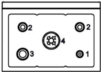
SURFACE BURNER LAYOUT
Reflect names from brochure
- Small Burner
- Medium burner
- Rapid burner
- Dual burner (Power burner)
Models
MAS36 5 GAS XTLP
[M3W0GNA7X(2,5)AUA]
MAS36 5 GAS XELP
[M3W0GNA7X(2,5)AUG]
ROOM VENTILATION
The use of a gas cooking appliance generates heat and humidity in the room where it is installed. Proper ventilation in the room is needed. Make sure the kitchen is equipped with a range hood of appropriate power (400 CFM minimum). Activate the exhaust fan/range hood when possible. Intensive and continuous use the appliance may require additional ventilation, for example by opening a window.
of
SURFACE COOKING
SYMBOLS
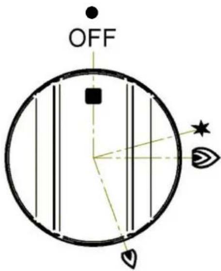

Burner position (in this case front left burner).

Maximum temperature
setting / Recommended control knob position for burner ignition

Minimum temperature setting
SURFACE BURNER OPERATION
THERMOCOUPLE SAFETY VALVE
Each surface burner of a Bertazzoni range is equipped with a thermocouple safety device.
The thermocouple opens the flow of gas to the burner only when hot. Should the flame go off, the thermocouple will immediately close the gas flow to the burner eliminating any risk to your home.
For faster activation of the thermocouple, always light the burners on maximum power. This will allow the thermocouple to reach the optimum temperature in the fastest time.
ELECTRIC IGNITION
To activate the electric ignition, simply turn the control knob counter-clockwise to maximum power (position). Press the knob to start the flow of gas and the ignition spark. The spark will released at the metal tip of the white ceramic pin located on the side of the burner. Once the flame is on, release the control knob gently.
If the flame turns off, repeat the above procedure.
The dual power-burner is composed by two burners (inside and outside). Each burner is activated by a separate control knob. The two burners can be operated separately or together for maximum power. To activate the power-burner, turn on the central burner first, then turn on the external ring.
ATTENTION: do not ignite burners if the black burner cap is not installed or not centred. The flame will be irregular.
MANUAL IGNITION
Manual ignition is always possible even when the power is cut off or in the event of power failure.
Turn the control knob counter-clockwise to the MAXIMUM position. Light the flame with a kitchen lighter or with a match.
TIPS FOR USING BURNERS CORRECTLY
WARNING!
KEEP CHILDREN AT A SAFE DISTANCE FROM THE APPLIANCE DURING OPERATION.
DO NOT ALLOW CHILDREN TO OPERATE THE APPLIANCE.
- Always check that the burner caps are properly installed before operation.
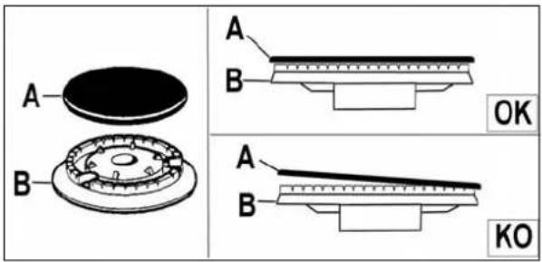
- Verify that the flame of the worktop burners is completely blue and with regular aspect as shown below.
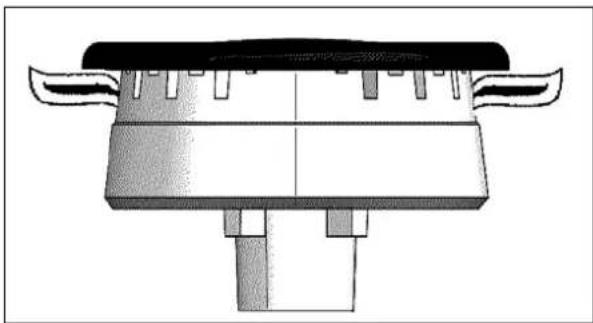
natural_image
Technical line drawing of a mechanical component with symmetrical features and a central shaft (no text or symbols)- Always adjust the burner flame so it does not extend beyond the edge of the pan.
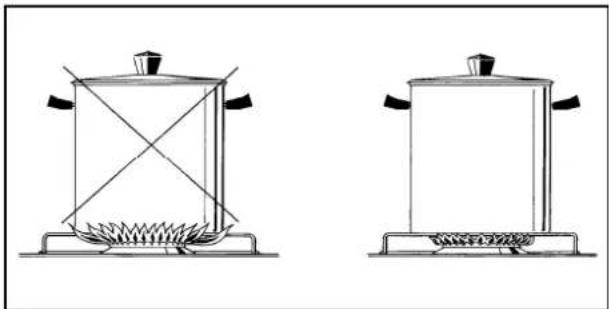
natural_image
Two simple line drawings of a portable stove with heating elements, no text or symbols present.TIPS FOR USING PANS CORRECTLY
ATTENTION!
Always ensure that bottom and handles of pans do not protrude from the worktop.
When cooking with flammable fat such as oil, do not leave the range unattended.
Use pots of the appropriate size on each burner following the indication of the diagram below.
| Burner | Recommended pan size inches (mm) |
| Small | 3 12 "-51/2"(90 – 140) |
| Medium | 51/2"- 101/4"(140 – 260) |
| Large | 71/8"- 101/4" (180 – 260) |
| Dual burner | 82/3"-101/4" (220 – 260) |
When boiling liquids, turn the knob to the MINIMUM position once boiling is reached to avoid overflow.
Always use pots with matching lid.
Dry the bottom of pans before operation.
Use pots with a flat, thick bottom (except for wok cooking).
WOK COOKING: always use the wok adapter supplied with the range. Wok pan external diameter shall not be smaller than 10" (25cm) and larger than 16" (40cm).
SIMMERING: use the simmer ring supplied with the range.
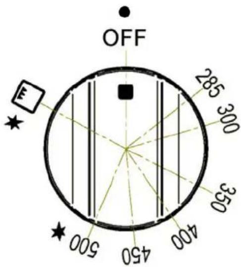
OVEN COOKING
SYMBOLS
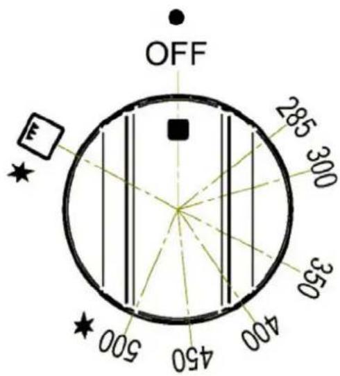

Thermal bake selector

Broiler selector

Recommended control knob position for burner ignition
285F Mimum oven temperature setting
500F Maximum oven temperature setting
Oven on/off Oven status indicator.
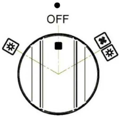
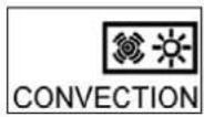
Convection fan and oven compartment light switch

Oven compartment light switch for baking or broiling
OVEN SHELVES
Bertazzoni ranges are equipped with commercial grade shelves and a enamel cooking tray.
Shelves are mounted on the appropriate guides situated on the sides of the oven compartment. Insert the shelf between top and bottom guide in any of the 5 positions available.
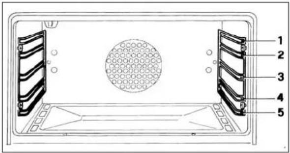
To keep the oven as clean as possible, cook meat on the tray.
When available, always follow recipe book directions. Personal experience will help to determine any variations in the values reported in the table. In any case, it is recommended to follow the instructions of the specific recipe being used.
GAS OVEN OPERATION

WARNING
NEVER cover any slots, holes or passages in the oven botton or cover an entire rack with materials such as aluminum foil. Doing so blocks air flow through the oven and may cause carbon monoxide poisoning. Aluminum foil linings may also trap heat, causing a fire hazard.
THERMOCOUPLE SAFETY VALVE
Bertazzoni gas ovens are equipped with a thermocouple safety device and a thermostat to set the proper cooking temperature.
The thermocouple opens the flow of gas to the burner only when hot. Should the flame go off, the thermocouple will immediately close the gas flow to the burner eliminating any risk to your home.
For faster activation of the thermocouple, always light the burners on maximum power. This will allow the thermocouple to reach the optimum temperature in the fastest time.
ATTENTION!
When using the oven for the first time it should be operated for 15-30 minutes at a temperature of about 500^ F/260°C without cooking anything inside in order to eliminate any moisture and odours from the internal insulation.
ELECTRIC IGNITION
WARNING!
Always keep the oven door open when lighting the oven.
Warning: Do not use the gas oven or broiler in case of electric power failure
Open the oven door, turn the knob to the maximum temperature setting, press well the knob for 1 sec. And relase it, the automatic ignition system will automatically generate the spark for 5 seconds and will engage the termocouple. Then check that the oven burner flame is and remain correctly lit, and close the door.
Do not press the oven knob for more than 2,5 sec. otherwise automatic ignition system lock itself and it will be necessary to retry the whole ignition sequence; if the oven burner do not remain correctly lit at the first attempt, open the door of the room and wait at least 60 sec. before to retry to ignite the oven burner.
WARNING
If the oven burner flame is extinguished accidentally during operation, turn the temperature control knob counter-clockwise to the off position. Wait at least 60 seconds before attempting to light the oven again.
CONVECTION COOKING
Bertazzoni gas oven are equipped with a CONVECTION fan.
In convection mode, the fan situated at the back of the oven compartment creates horizontal forced-air circulation. The advantages of convection cooking are:
-
uniform distribution of heat throughout the oven cavity (meat no longer needs to be turned while roasting)
-
cooking different types of food at the same time, without flavour transmission from one dish to the other.
Pre-heating the oven is not necessary. For delicate pastry baking, it is recommended to heat the oven before inserting the pastry trays.
To activate the convection fan use the selector placed on control panel.
COOKING WITH THE GAS BROILER
WARNING
Always keep the oven door open when lighting the gas broiler.
The gas broiler is activated with the same control knob used for setting the oven temperature.
To activate the broiler, turn the control knob clockwise in the broiler position.
The broiler burner always operates at maximum power and therefore there is no temperature setting.
ELECTRIC IGNITION
Warning: Do not use the gas oven or broiler in case of electric power failure
Open the oven door, turn the knob to the broiler position setting, press well the knob for 1 sec. And relase it, the automatic ignition system will automatically generate the spark for 5 seconds and will engage the termocouple. Then check that the broiler burner flame is and remain correctly lit, and clese the door.
Do not press the broiler knob for more than 2,5 sec. otherwise automatic ignition system lock itself and it will be necessary to retry the whole ignition sequence; if the broiler burner do not remain correctly lit at the first attempt, open
the door of the room and wait at least 60 sec. before to retry to ignite the broiler burner.
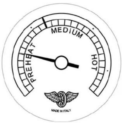
USING THE THERMOMETER
Only model MAS36 5 GAS XTLP
The range is fitted with a device that gives a quantitative indication of the temperature in the middle of the oven.
MAINTAINING YOUR RANGE
REPLACING THE OVEN LIGHT BULB
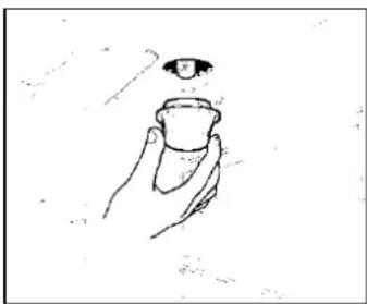
WARNING!
Disconnect power before servicing unit.
To replace the oven light bulb, unscrew the protection cap that projects out inside the oven.
Spare bulbs are available at factory-authorized parts resellers listed on page 4.
Alternatively use commercial bulbs type [list SPECS]
natural_image
Hand holding a small object with an eye above it (no text or symbols)COOLING FAN FAILURE
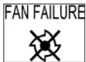
Bertazzoni ranges are equipped with a cooling fan. The fan starts operating each time the oven knob is on a position different from 0 (zero).
The fan circulates the air between the control panel and the oven door, allowing the control panel and the oven door to remain cool while cooking.
Malfunction of the cooling fan is indicated by the FAN FAILURE light situated at the left side of the control panel. If the light is on, turn off all burners as soon as possible and call the customer service hotline to schedule service by a factory-trained professional.
CLEANING YOUR RANGE
ATTENTION!
Never use abrasive cleaners!
Scratches on the stainless steel surfaces are permanent.
Do not clean the range when hot!
Cleaning after installation: use a stainless steel cleaning product or wipe to eliminate the glue residues of the blue protection film after removal.
Cleaning the worktop: periodically clean the burner heads, the cast iron pan supports and the burner caps using warm water. Remove burned food and fat residues with a rubber spatula. If food residue prevent the smooth operation of the control knobs, call the customer service hotline to schedule service by a factory-trained professional.
Cleaning stainless steel best results use a stainless steel cleaner product with a soft sponge or wipe. Alternatively use a soft sponge or cloth with a warm soap and water solution. Never use abrasive powders or liquids!
Cleaning the burner caps: lift the burner caps from the burner heads and wash them in a warm soap and water solution. Dry thoroughly before using them again. Before reinstalling them on the burner head, check that the gas flow holes are not clogged with food residues or cleaning product residues.
Cleaning Enamel: enamelled parts should be cleaned frequently with awarm soap and water solution applied with a soft sponge or wipe. Never use abrasive powders or liquids! Do not leave acid or alkaline substances on the enamelled parts (such as vinegar, lemon juice, salt, tomato sauce, etc.). Use a rubber spatula to remove fat residues.
Cleaning glass door: clean the glass using a non-abrasive sponge or wipe with a warm soap and warm water solution. Use a rubber spatula to remove fat residues.
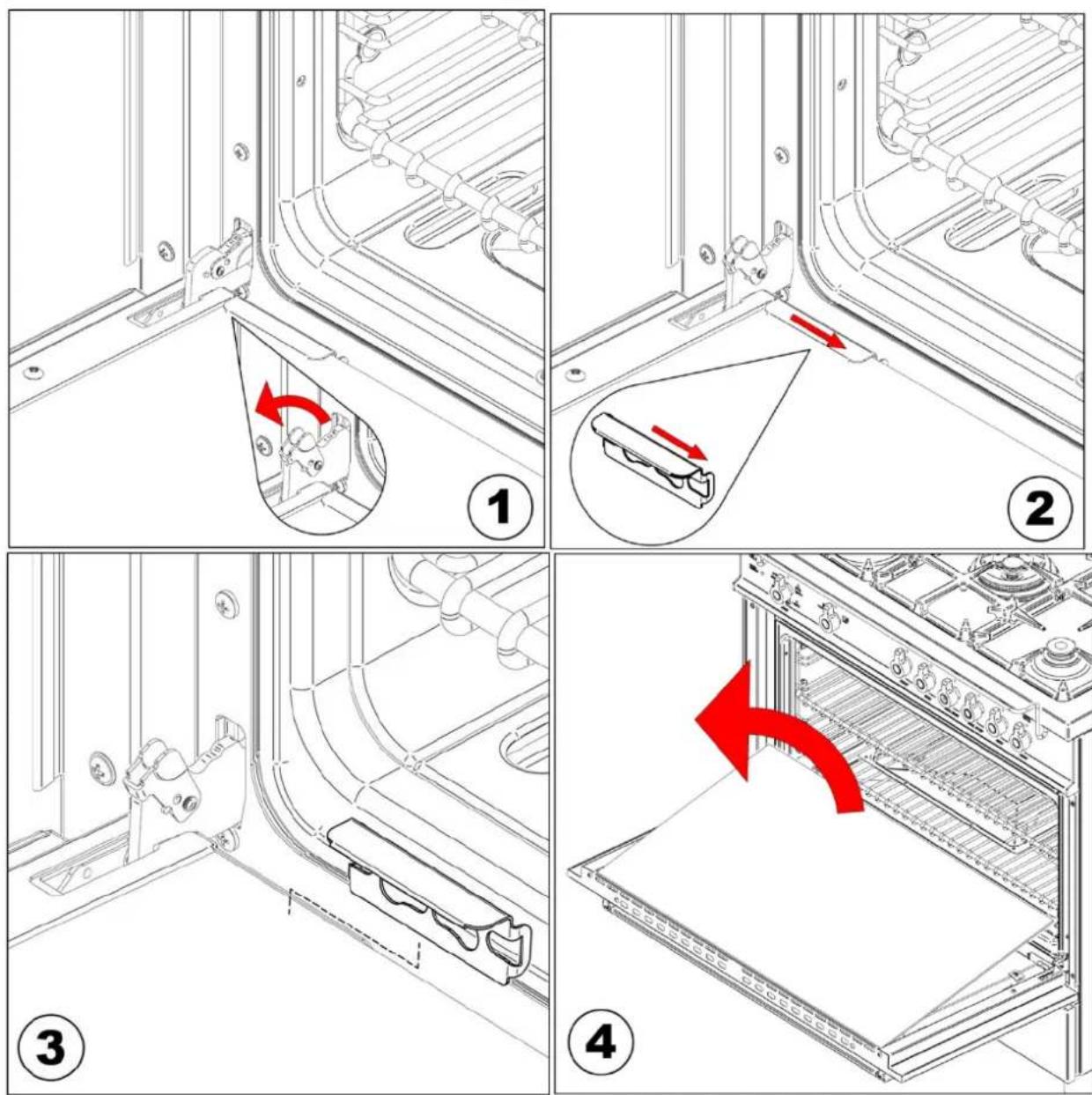
Cleaning the inside of the oven glass: Oven feature is the ability to remove the inner glass. After you open the door completely and lock the hinges (fig. 1) unhook the engagements shows the figure (2-3) lift and remove the inner glass (fig. 4) and then clean the crystal. Such an operation is to be performed in cold oven and with a damp cloth, taking care not to use
abrasives. To reassemble the glass do the opposite making with the same orientation that has been disassembled, remembering that the smooth part both in vista and the remains inside the screen-printed glass oven door. Once you have reassembled the glass block with the engagements and unlocking hinges.
Caution: do not loosen the hinges if the inner glass is not mounted on the door.
Clean the inside of the oven: To facilitate intensive cleaning of the oven is easy to disassemble the door by following the below instructions. After you open the door completely and lock the hinges (fig. 1), put the door in a semi-open position and using both hands pull it
towards you until it is released from the attachment.. To reassemble the door operate in reverse order. They are also easily off the side grids, by unscrewing the nuts that fasten the oven.
ATTENTION: while cleaning the door, avoid spillage of food residues and cleaning products in the venting holes situated on the top side of the door. To clean the inside of the oven door, call a factory-trained professional.
ATTENTION: for further details about cleaning of the appliance, please contact your appliance retailer.
IMPORTANT APPLIANCE INFORMATION
MODEL
DATE INSTALLED
DEALER
INSTALLER
SERVICER

BERTAZZONI SpA
Via Palazzina 8
42016 Guastalla RE
ITALY
WWW.BERTAZZONI.COM