
IT-G600 - Mobile Phone CASIO - Free user manual and instructions
Find the device manual for free IT-G600 CASIO in PDF.

| Product Type | Rugged Mobile Phone |
| Brand | Casio |
| Model | IT-G600 |
| Dimensions | Approx. 154 x 79 x 23 mm |
| Weight | Approx. 250 g |
| Battery Type | Li-ion rechargeable |
| Battery Capacity | 3000 mAh |
| Water & Dust Resistance | IP68 certified |
| Drop Resistance | MIL-STD-810G compliant |
| Operating System | Proprietary or Android-based (likely AOSP) |
| Display | 2.8-inch color LCD, 320x240 px |
| Camera | Rear camera with flash |
| Connectivity | Bluetooth, USB, Wi-Fi (optional) |
| GPS | Integrated GPS module |
| Key Features | Rugged design, loud speaker, push-to-talk, programmable keys |
| Maintenance & Cleaning | Wipe with dry cloth; avoid solvents; keep ports sealed after cleaning |
| Safety | Use only approved batteries and chargers; avoid exposure to extreme heat |
| Spare Parts & Repairability | Battery, charger, USB cable, custom housing available from authorized service |
Frequently Asked Questions - IT-G600 CASIO
User questions about IT-G600 CASIO
0 question about this device. Answer the ones you know or ask your own.
Ask a new question about this device
Download the instructions for your Mobile Phone in PDF format for free! Find your manual IT-G600 - CASIO and take your electronic device back in hand. On this page are published all the documents necessary for the use of your device. IT-G600 by CASIO.
USER MANUAL IT-G600 CASIO
Rugged Smart Handheld Terminal
IT-G600 IT-G650 Series
User's Guide
Be sure to read "Safety Precautions" inside this guide before trying to use your Rugged Smart Handheld Terminal.

text_image
CASIO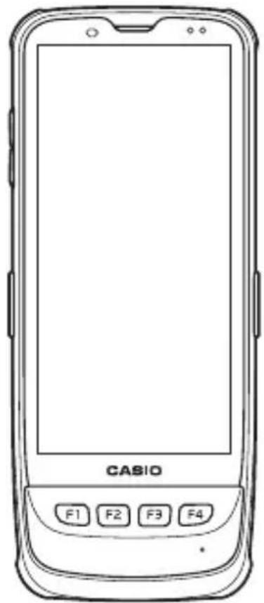
natural_image
Line drawing of a Casio mobile phone with front panel and control buttons (no text or symbols on body)Trademarks and Licenses

Bluetooth
Bluetooth is a registered trademark owned by Bluetooth SIG, Inc. and licensed to CASIO COMPUTER CO., LTD.
Google™, the Google logo, Android™ and the Android logo are trademarks or registered trademarks of Google LLC.
SD, SDHC, SDXC, microSD, microSDHC and microSDXC are trademarks of SD-3C LLC.
FeliCa is a registered trademark of Sony Corporation.
All other company or product names mentioned herein are trademarks or registered trademarks of their respective owners.
This product uses software licensed on the basis of GNU General Public License (GPL), GNU Lesser General Public License (LGPL) and other licenses. Relevant terms and conditions shall also apply to this software.
For details on licenses, see "Settings" → "About phone" → "Legal information" → "Third-party licenses".
Contents
Important....2
Warning Label 2
Safety Precautions ....3
Regulatory Information 8
Operating Precautions ....8
About the Waterproofing/Dustproofing....11
Accessories and Options 12
Part Names 13
Getting Ready to Use 18
Installing and Replacing the Battery Pack ....18
Installing and Removing the AC Adapter 22
Charging the Battery Pack 23
Using the Stylus Retaining Cord 26
Attaching the Neck Strap and Stylus 26
Attaching the Hand Belt 27
Using a nanoSIM Card 28
Using a microSD Card ....30
Using the Laser Scaner ....31
Handling the NFC 32
Making the Touch Panel Easier to Use ....33
Turning the Power On/Off and Sleep 34
Performing Communications ....35
Rebooting or Resetting the Terminal 36
IT-G600/G650 Specifications 37
USB Cradle (HA-U60IO) 43
Ethernet Cradle (HA-U62IO).... 45
Multiple Battery Charger (HA-U36DCHG) 48
Dual Battery Charger (HA-U32DCHG).... 53
USB Type-C Cable (HA-S81USBC) 56
Battery Pack (HA-U20BAT) 57
Important
• Information in this document is subject to change without advance notice. CASIO Computer Co., Ltd. makes no representations or warranties with respect to the contents or use of this manual and specifically disclaims any express or implied warranties of merchantability or fi tness for any particular purpose.
- The descriptions in this manual apply to multiple handheld terminals. Unless otherwise specified, the IT-G600 is used in the descriptions, sample screens and illustrations.
After Service
- Should this product ever malfunction, contact your original retailer providing information about the product name, the date you purchased it, and details about the problem.
Warning Label
IT-G600-C21/WC21
IT-G650-C21/WC21
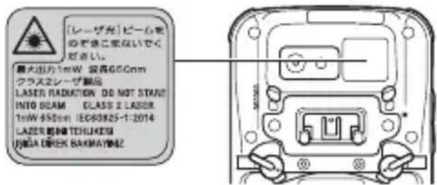
IT-G600-C31/WC31
IT-G650-C31/WC31
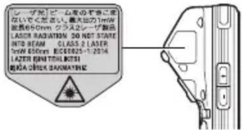
- This label is a warning and caution label for Class 2 laser products that comply with IEC60825-1:2014.
- Although Class 2 laser light is only emitted momentarily, never look directly into the beam light.
- The laser light emitted by this laser scanner has a maximum output of less than 1 mW and a wavelength of 650 nm.
- Use of controls or adjustments or performance of procedures other than those specified herein may result in hazardous radiation exposure.
- Toute manipulation a l'aide de procedures autres que celles spécifiées dans ce Mode d'emploi est dangereuse et doit être evitee.
Safety Precautions
Congratulations upon your selection of this CASIO product. Be sure to read the following Safety Precautions before trying to use it for the first time.
Your neglect or avoidance of the warning and caution statements in the subsequent pages causes the danger of fire, electric shock, malfunction and damage on the goods as well as personal injury.
Markings and Symbols
The following are the meanings of the markings and symbols used in these Safety Precautions.
 | Danger | This symbol indicates information that, if ignored or applied incorrectly, creates the danger of death or serious personal injury. |
 | Warning | This symbol indicates information that, if ignored or applied incorrectly, creates the possibility of death or serious personal injury. |
 | Caution | This symbol indicates information that, if ignored or applied incorrectly, creates the possibility of personal injury or property damage. |


- A diagonal line indicates something you should not do. The symbol shown here indicates you should not try to take the unit apart.
- A black circle indicates something you should do. The symbol shown here indicates you should unplug the unit from the wall outlet.
Operating Precautions
| Warning | |
Disassembly and Modifi cation ......prohibited ......prohibited | ·Never try to disassemble or modify the terminal and its options including battery pack and battery in any way. |
Abnormal Conditions | ·Should the terminal and/or its options including battery pack and battery become hot or start to emit smoke or a strange odor, immediately turn off the power and contact your dealer or distributor whom you purchased the product from, or an authorized CASIO PA repair center. |
Foreign Objects Prohibitions Prohibitions | ·Take care to ensure that metals or combustible objects are not inserted into the openings of the terminal or its options, and not to allow moisture to get inside of them. |
Dust and Moisture | ·Though the terminal is dust- and waterproof structure, its options including the battery pack are not. Keep loose metal objects and containers filled with liquid away from your terminal and the options. Also, never handle the terminal and the options while your hands are wet. |
Laser Light | ·This product uses laser light. Never look directly into the laser light or shine the laser light into the eyes.·Ce produit utilise une lumière laser. Ne regardez jamais directement la lumiere laser ni ne dirigez la lumiere laser dans les yeux de quelqu’un. |
Warning
Avoid contact with fi re

Prohibitions
- Do not bring the terminal into contact with fire. Doing so could cause the battery to burst and result in a fire or injury.
Storage and Operation Locations
Do not store or use the product in any of the locations described below.
- Areas subjected to large amounts of moisture and dust.
- Near a heating device, on an electric carpet, in a location exposed to direct sunlight, in a car parked outside, or any other area where the product is subjected to high temperatures.
- Food preparation areas, near a humidifier, or in areas where the product is exposed to oil smoke or water vapor.
- Areas where there is strong vibration.
- Do not place the product on an unsteady platform, on a high shelf, or in any other unstable location.
Location

• Install the cradle properly on a flat and stable surface so that it cannot fall down onto floor.
Other areas where there are high or low temperatures. (Operating temperature range: -20 to 50°C, Charging temperature range: 0 to 40°C)
Do not place heavy objects on the product.
- Dropping and tipping over create the risk of personal injury.
LCD Screen

Prohibitione
- Never apply strong pressure to the screen or subject it to strong impact. Doing so can crack the LCD Screen.
Should the LCD become cracked, never touch any of the liquid inside.
- LCD liquid getting on the skin creates the risk of skin irritation.
- Should LCD liquid get into your mouth, immediately rinse your mouth out and contact your physician.
- Should LCD liquid get in your eyes or on your skin, rinse with clean water and then contact your physician.
Locations exposed to fl ammable gases
- Before entering locations where flammable gases may occur, such as a gas station, always ensure that the terminal is switched off. Failing to do so could cause the gases to ignite.
Low Temperature Burn

Prohibitions
- Avoid prolonged contact with the skin while the terminal is switched on. Some areas on the back of the terminal may become hot during use and could cause low-temperature burns.
Avoid Use While In Motion
- Do not use the product or view the monitor while operating an automobile or other vehicle, or while walking.
Caution
LED Light, Scanner and Other Light Emitting Functions

Prohibitions
- Do not fire LED light, the scanner or other light emitting functions while pointed in the direction of a person operating a motor vehicle.
Using the Wireless Data Communication Function
Warning
Interference with the Operation of Other Equipment (Using Wireless Data Communication)

- Should you notice radio interference or other problems on other devices is being caused while using this product, do not use the wireless function.
- When using the product in a medical facility or aircraft, follow the instructions of local personnel and crew concerning use of such devices.
Do not use the product in an area where use of such devices is prohibited.
- Do not use the product in the vicinity of high-precision electronic equipment or any electronic equipment that handles weak signals.
- Keep this product away from the chest area of any individual fitted with a cardiac pacemaker.
- Turn off the wireless function and the product while on a train or in any other crowded location.
- Turn off the wireless function or enter the Airplane Mode while on a train or in any other crowded location.
Lithium-ion Battery Pack
Danger

- Never use the terminal and its option including the battery pack and battery next to open flame, near a stove, or any other area exposed to high heat, or leave them for a long period of time in a vehicle parked in direct sunlight.
- Never use the battery pack with any device other than the terminal.
- Never dispose of the battery pack by incinerating it or otherwise expose it to heat.
- Never transport or store the battery pack together with metal objects that may result in shorting positive (+) and negative (−) terminals of the battery pack. Be sure to place the battery pack in its case whenever transporting or storing it.
- Never throw the battery pack or otherwise subject it to strong impact.
- Never pierce the battery pack with nails, hit it with a hammer, or step on it.
- Do not use or leave a battery pack in a location exposed to direct sunlight, in an automobile parked outside, near open flame, a stove, or in any location subjected to high heat.
- Never place the battery pack in a microwave oven or any other high-voltage device.
- Use only the specified battery charger to charge the battery pack.
- Charge a battery using only the method specifically described in user documentation.
- Do not allow a battery to come into contact with fresh water, salt water, or other moisture. Do not use a battery that is wet.
- Load a battery with its poles (plus (+) and minus (-)) facing correctly.
- Should fluid from the battery pack accidentally get into your eyes or on the skin, do not rub it. Immediately rinse it off with clean tap water and then consult a physician.

| Warning | |
| Immediately after noticing any fluid leak, abnormal odor, overheating, discoloration, deformation or other battery abnormality, very carefully remove the battery from the product and/or charger.Keep the removed battery away from fire. Do not use a battery exhibiting any abnormality.If the amount of time period the battery pack can serve becomes considerably short even after it has been fully charged for the specified time period, stop using it.Should the battery pack start to leak or emit a strange odor, immediately move it away from any flame nearby. Leaking battery fluid is combustible.If a battery is not charged even if the specified charging time is exceeded, stop charging.Always use only the specifi ed type of battery. | |
| Caution | |
| Prohibitions | Do not leave a battery near areas used by animals.Do not use a battery that is severely swollen.Do not leave the battery pack and the terminal in a high or low temperature environment while using, storage or transportation the battery. Explosion, flammable liquid or gas may leak.The battery pack and the terminal subjected to extremely low air pressure may result in an explosion, the leakage of explosion or the leakage of flammable liquid or gas. |
| Replace only with the same type of battery pack recommended by CASIO. Dispose of used battery packs according to the local regulation.Keep the battery pack out of the reach of small children.Risk of explosion if battery is replaced by an incorrect type. Dispose of used batteries according to the instructions. | |
Power Supply / AC Adapter
| Warning | |
| Prohibitions | Do not use the terminal at a voltage other than the specified voltage. Also, do not connect the terminal to a multi-plug power strip.Never modify, sharply bend, twist, or pull on the power cord.Never use a detergent to clean AC adapter and its power cable, especially on the plug and the jack.Do not use an AC adapter with a bent connector.Do not twist or wrench the connector.When using the battery chargers and the cradles, be sure to use the respective AC adapters. |
| Prohibitions | Never pull on the power cord when unplugging it.Never touch the plug while your hands are wet.Do not use the AC adaptor while it is wet.** Avoid water, sports drinks, seawater, animal or pet urine, and other liquid.Be sure to unplug the power cord from the wall outlet before cleaning the battery chargers and the cradles.Unplug the power cord from the wall outlet whenever leaving the battery chargers and the cradles unattended for a long period.Use the included power cord with this product only.Use only the specifi ed type of AC adaptor.Use only the included power cord.Insert the power plug into the outlet as far as it will go.Continued use creates the risk of fi re and electric shock.Do not place a flower vase or any other liquid container on top of the AC adaptor or power cord.Before leaving the product unattended, unplug the AC adaptor from the power outlet, and move the product to a location away from animals. |
| Caution | |
 | Check that the connector is properly oriented and then push it straight in (do not insert upside down).Do not allow fluids or foreign objects to get into the AC adapter.Choose a location where the power cord is readily accessible and can be easily plugged in and unplugged.When using the AC adapter, always use a power outlet with the specified power supply and voltage, and ensure that the power plug is inserted into the socket fully and securely. |
 Unplug from the power supply Unplug from the power supply | At least once a year, unplug the AC adapter from the wall outlet and clean any dust that builds up between the prongs of the plug.Dust built up between the prongs can lead to the danger of fi re. |
 | The housing of the AC adapter can become warm during normal use. |
 | Pay attention to electric shock. |
 Unplug from the power supply Unplug from the power supply | If you do not plan to use the product for a long time, unplug from the power outlet. |
Backup of All Important Data
| Caution | |
 | Note that CASIO Computer Co., Ltd. shall not be held liable to you or any third party for any damages or loss caused by deletion or corruption of data due to use of the terminal, malfunction or repair of the terminal or its peripherals, or due to the batteries going dead.The terminal employs electronic memory to store data, which means that memory contents can be corrupted or deleted if power is interrupted due to the batteries going dead or incorrect battery replacement procedures. Data cannot be recovered once it is lost or corrupted. Be sure to make backup of all important data. |
Use Casio genuine battery pack only
| Danger | |
 | We recommend the use of Casio genuine battery packs with Casio devices. Casio genuine battery packs are tested for quality and safety for the safe use of the product they are installed. We cannot be held liable for accidents or damages caused by counterfeit Casio battery packs or battery packs other than Casio genuine battery packs. When buying a battery pack, pay due attention to buy a Casio genuine battery pack. |
Europe
IT-G600
IT-G650
Options of
IT-G600/IT-G650

Manufacturer:
CASIO COMPUTER CO., LTD.
6-2, Hon-machi 1-chome, Shibuya-ku, Tokyo 151-8543, Japan
Importer
Casio Europe GmbH
- Please keep all information for future reference.
- The full text of the EU declaration of conformity is available at the following internet address: http://doc.casio.com/
- Products are for distribution within all member states of the EU.
Options of IT-G600/IT-G650 are HA-U60IO, HA-U62IO, HA-U36DCHG, HA-U32DCHG, HA-U20BAT, AD-S50400A, AD-S12500A, AD-S50200A, HA-S81USBC.
For Europe models are IT-G600-C21, IT-G600-WC21, IT-G600-C31, IT-G600-WC31,
IT-G600-WC01, IT-G650-C21, IT-G650-WC21, IT-G650-C31, IT-G650-WC31.
Maximum radio output power
- IEEE802.11a/b/g/n/ac: 2.4GHz≤20dBm, 5GHz≤16dBm
- Bluetooth: 2.4GHz≤10dBm
• GSM: 900MHz≤33dBm, 1800MHz≤30dBm - WCDMA: 850 / 900MHz≤ 24dBm,1900MHz≤ 24dBm
- LTE: 850/900MHz≤23dBm, 1800/1900MHz≤23dBm, 2500MHz≤23dBm
- NFC: 13.553MHz to 13.567MHz band -4.9dBμA/m at 10m.
Hereby, “CASIO COMPUTER CO., LTD.” declares that the radio equipment type “IT-G600/IT-G650” is in compliance with Directive 2014/53/EU.
Operating Precautions
Your terminal and its options are precision. Improper operation or rough handling can cause problems with data storage and other problems. Note and observe the following precautions to ensure proper operation.
- Do not continue using the battery once it is exhausted.
Doing so could result in data loss or corruption. When the battery is exhausted, replace it immediately.
- Stop or avoid using the terminal and its options in areas and conditions subject to the following.
— Large amounts of static electricity
— Extreme heat or cold or humidity
— Sudden temperature change
— Large amount of dust
— After large amount of rain or water falls on the terminal
— Pressing the screen or keys with excessive force when using in the rain
- Use the pad of your finger or the dedicated stylus to operate the touch panel.
- Use the dedicated stylus to operate the Reset switch.
- Do not use volatile chemical substances such as thinners, benzene or toiletries to clean the terminal.
When the terminal is dirty, wipe it clean with a soft, dry cloth. Rubbing with excessive force could scratch the display.
- The power-supply terminals and Data Communication terminals should be cleaned periodically using an implement such as a dry cotton bud.
Soiling on the terminals may cause connection defects.
• Take care when using chemicals.
Applying thinners, gasoline, kerosene, solvents or oils, or substances such as cleaners, adhesives, paints, medications or toiletries that contain those materials, to the plastic case or cover may cause discoloration or other damage.
- LCD panel
The following are characteristics of the LCD panel and do not indicate a fault.
— The LCD panel is manufactured using high-precision technology and features a minimum of 99.99% effective pixels. There may be some pixels that fail to light or that remain permanently lit.
— If the same screen is displayed on the panel for a prolonged period, its afterimage may persist after a new screen is displayed. The afterimage will fade after a few moments.
• 802.11a/n/ac Restrictions
— This product is for indoor use only when using channels 36, 40, 44, 48, 52, 56, 60, or 64 (5150-5350 MHz).
— To ensure compliance with local regulations, be sure to select the country in which the access point is installed.
- Do not use a strap other than the one supplied.
• Lithium-ion Battery Pack
Each lithium-ion battery pack has its life. The life span heavily depends on how the battery pack is charged or stored which may cause deterioration of the battery pack to shorten the life span if it is handled improperly. Note the tips below to make the battery pack last long.
— Be sure to charge the battery pack before using it if the battery pack is used for the first time or if it has not been used for a long period of time. When charging the battery pack, continue charging until the charge LED lights green (fully charged).
— If the battery pack is repeatedly charged, the life span becomes short. To avoid the repetition of charging the battery pack, be sure that the remaining capacity is low before you start charging.
— Be sure to charge the battery pack in recommended temperature range. The temperature range is dependant on device you use to charge including battery chargers and tablets. Refer to the respective user guides (download version). Charging the battery pack in a temperature outside of the recommended range causes deterioration.
— When used at low temperatures, the battery pack has a reduced capacity and will supply power for shorter time. The life span of the battery pack is also shortened.
— Charging the battery pack while the battery pack itself is freeze including inside causes deterioration. Be sure to resume an ordinary room temperature on the battery pack and then leave it unattended for approximately one hour before charging.
— After charging the battery pack, if the performance of the battery pack does not show any recovery, it is a sign of ending the life. Replace it with a new battery pack.
— Avoid the battery pack with a full of the capacity to store for a long period of time. If you need to store it for a long period, be sure that the remaining capacity is 30 to 50 percent and to store in a moderate low temperature. This can reduce deterioration. Note also that even when not being used, the battery pack will gradually discharge. If this situation continues for a long period (several months or more), the battery pack will become overdischarged, which may impair quality and performance.
— The battery pack gradually deteriorates over time. In particular, storing (or using) the fully charged battery pack at high temperatures tends to accelerate battery pack deterioration.
- Drop resistance
The drop resistance is a test value only and is not guaranteed.
Repeated or frequent shocks may still result in damage, so the terminal should be handled so as to avoid impacts.
- Water or other moisture on the power-supply or data communication terminals could cause sparking or an electric shock, and soiled contacts could block the connection and impair charging functionality.
- While the IT-G600/IT-G650 is waterproofed, note the following when using this product:
- If the IT-G600/IT-G650 is exposed to water droplets, thoroughly wipe off the moisture with a dry cloth.
- Do not use the IT-G600/IT-G650 for long periods in the rain.
- Securely close the battery pack cover and connector covers when using the IT-G600/IT-G650.
- Do not press hard on the screen (touch panel) or keys when using the IT-G600/IT-G650 in the rain.
- The back of the IT-G600/IT-G650 may become warm during use. This is normal and does not indicate a fault.
- Weld Lines
There are seam-like markings in some locations on the terminal. These are referred to as “weld lines” in the plastic forming process and are not cracks or scratches. Weld lines do not interfere in any way with the operation of the terminal.
- Limited-life parts
This product includes limited-life parts (memory, LCD panel, etc.).
The approximate period for which limited-life parts can be used differs according to the frequency of use and other conditions. However, in normal use, this period is roughly 5 years assuming the product is used for roughly 8 hours per day.
The above period is intended solely as a general guide and in no way guarantees that the parts will not develop a fault or will be repaired at no cost within that period.
Note also that in some types of use, such as extended continuous use, the parts may need to be replaced (at a fee) sooner or within the product warranty period.
• Repairs to terminals configured with a Google account
If a terminal needing repairs has been configured with a Google account, delete the Google account settings before sending the terminal to be repaired.
During repairs, Casio resets the terminal to the factory default status. However, terminals with a Google account are equipped with the Google device protection function, which prevents unauthorized use in the event that it is lost or stolen. To reset a terminal configured with a Google account to the factory default status, the Google account credentials must be entered. For this reason, the user must delete the Google account settings registered in the terminal.
Refer to the following website for information on how to delete the Google account settings: https://www.casio-intl.com/asia/en/support/ht/android_repair/
-
- Updating the system also applies any security updates.
- CASIO COMPUTER Co., Ltd. will also provide updates to the OS at regular intervals or as deemed necessary by Casio.
- System administrators should also update the OS as appropriate and should run the latest version of the OS.
- Refer to the software manual for information on how to update the OS.
- When updating the OS, check that the battery has sufficient charge remaining.
The IT-G600/IT-G650 Series models are waterproof and dustproof.
Important!
The water- and dust-proofing performance of this product is based on CASIO testing procedures. Note also that this performance applies to the product at the time of shipment (delivery to the customer) and is not guaranteed inclusive of the environment in which the product is used. The warranty does not apply to any situation where the product is immersed during use, and as with any other electrical product, great care should be taken when using this product in the rain or similar situation.
• Precautions When Using this Product
— Check that there is no dust, sand or other foreign matter on the battery pack cover, headset jack, USB port cover or respective contact surfaces. If any soiling is found, wipe it off with a clean, soft, dry cloth. Even very small amounts of soiling trapped on the contact surfaces (a single hair or grain of sand, etc.) can cause water to leak into the device.
— Check that the waterproof seals on the battery pack cover, headset jack and USB port cover are free from cracks and other damage.
— Close the battery pack cover lock switch firmly until the switch is in the locked position.
— Avoid opening and closing the battery pack cover, headset jack or USB port cover in locations near water or exposed to sea breezes, and do not open or close them with wet hands.
— While the USB port and headset jack are built to be waterproof, any water on the port or jack should always be wiped off.
— Do not drop this product or leave it in locations exposed to temperatures outside the specified range. Doing so could impair its water- or dust-proofing.
- Other Precautions
— The accessories for this product (battery pack, etc.) and optional products are not water- or dust-proof.
— Subjecting this product to a severe impact could render it no longer water- or dust-proof.
— If any water leaks into the product as a result of carelessness or inattention during product handling, CASIO cannot be held liable for compensation for any damage to internal components (battery, recording media, etc.) or for the costs of recorded content or the recording thereof.
— CASIO COMPUTER CO., LTD. accepts no other liability whatsoever for any accident that occurs due to water leakage.
Accessories and Options
Rugged Smart Handheld Terminal IT-G600 Series
Rugged Smart Handheld Terminal IT-G650 Series

natural_image
Line drawing of a Casio mobile phone with keypad and display screen (no text or symbols on device body)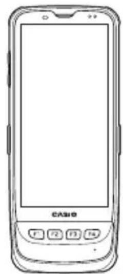
natural_image
Line drawing of a mobile phone with a blank screen and control buttons (no text or symbols)Accessories
Make sure all items listed below are included before using the terminal for the first time.
- Stylus
• Stylus Retaining Cord - Hand Belt
- Neck Strap
- Battery Pack
- User's Guide
Options
• USB Cradle HA-U60IO
- Ethernet Cradle HA-U62IO
• Multiple Battery Charger HA-U36DCHG
• Dual Battery Charger HA-U32DCHG
- Battery Pack HA-U20BAT
- Screen Protect Sheet (for IT-G600 (pack of 10)) HA-U90PS10
- Screen Protect Sheet (for IT-G650 (pack of 10)) HA-U92PS10
• Protector (for IT-G600) HA-U91BP1
• Protector (for IT-G650) HA-U93BP1
• AC Adapter (5V4A) AD-S50400A
• AC Adapter (12V5A) AD-S12500A
• Power Cord AC-CORD3-EU (for Europe)
• Power Cord AC-CORD3-UK (for United Kingdom)
• Power Cord AC-CORD3-AU (for Australia)
• USB AC Adapter (5V2A) AD-S50200A
- USB Type-C Cable HA-S81USBC
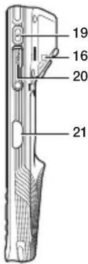
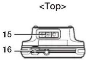
Terminal (IT-G600)

text_image

text_image
15 16 17 18 4 5 6 7 8 9 10 11 CA 100 7 14 13 12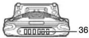
(With the battery pack cover fitted)
text_image
19 16 20 212

text_image
26 27 28 29 30 31 32
(With the battery pack cover removed)

text_image
33 35 34The illustration shows IT-G600-WC21.
| No. | Name Description | |
| 1 | Receiver Outputs audio. | |
| 2 | Charging Status LED Shows the | charging status or battery status. |
| 3 | Notification LED | Shows notifications. |
| 4 | Illuminance/Proximity Sensor | Measures the brightness or the proximity of an object. |
| 5 | Screen/Touch Panel | Displays text and operating instructions, etc. Can also be used to operate the terminal and enter data. |
| 6 | Center Trigger Key Used for scanning barcodes. Can also be assigned to any function. | |
| 7 | Function/Cursor Keys | Function in the same way as the up, down, left and right cursor keys on a computer. Can also be used to launch applications registered beforehand. |
| 8 | CLR Key Used to cancel entered data. | |
| 9 | SP Key Used to enter a space. | |
| 10 | Fn Key | Used in combination with number keys to confi gure settings or to launch applications registered beforehand. |
| 11 | Number/Period/Minus Keys Used to enter numbers or text. | |
| 12 | Microphone Inputs audio. | |
| 13 | Mode Key Used to switch to text input mode. | |
| 14 | Enter Key | Used when you have fi nished entering numbers or to move to the next step to be executed. |
| 15 | Volume Up Key Raises the volume. | |
| 16 | Strap Holes Used to attach the neck strap and stylus. | |
| 17 | Volume Down Key Lowers the volume. | |
| 18 | Left Trigger Key | Used for scanning barcodes. Can also be assigned to any function. |
| 19 | Power Key Turns the terminal on or off. | |
| 20 | USB Type-C Port | Connects the USB Type-C cable for USB communication. Can also be used to charge the terminal by connecting a USB AC adapter and USB Type-C cable. |
| 21 | Right Trigger Key | Used for scanning barcodes. Can also be assigned to any function. |
| 22 | Barcode Reader LED light shining from this scanner window scans barcodes. | |
| 23 | Headset Jack Connects an earphone-microphone. | |
| 24 | Camera Used to shoot photos or video. | |
| 25 | LED Light Used when shooting photos in dark locations. | |
| 26 | NFC Reader Reads data from designated cards held over the reader. | |
| 27 | Speaker Outputs alarm tones and other sounds. | |
| 28 | Hand Belt Mount Used to attach the Hand Belt. | |
| 29 | Battery Pack Cover Lock Switches | Slided to open or close the battery cover. |
| 30 | Battery Pack Cover The battery pack is installed inside this cover. | |
| 31 | Hand Belt Mount/Strap Hole | Used to attach the neck strap or hand belt. |
| 32 | Rear Microphone Used for Noise Canceling. | |
| 33 | microSD Card Slot Used to load a microSD card. | |
| 34 | Reset Switch Performs a hardware reset. | |
| 35 | nanoSIM Card Slot Used to load a nanoSIM card. | |
| 36 | Power Supply/Data Communication Terminals | Connects to the terminals in a cradle or similar device to supply power or enable USB communication. |
Terminal (IT-G650)
text_image

text_image
8 9 10 11 4 1 2 3 5 6 7 CASIO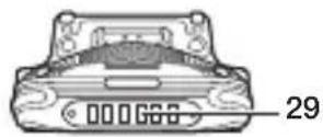
(With the battery pack cover fitted)

text_image
12 9 13 14
text_image
17 18 19 20 21 22 25 22 23 24
text_image
26 28 27The illustration shows IT-G650-W21.
| No. | Name Description | |
| 1 | Receiver Outputs audio. | |
| 2 | Charging Status LED Shows the | charging status or battery status. |
| 3 | Notification LED | Shows notifications. |
| 4 | Illuminance/Proximity Sensor | Measures the brightness or the proximity of an object. |
| 5 | Screen/Touch Panel | Displays text and operating instructions, etc. Can also be used to operate the terminal and enter data. |
| 6 | Function Key Used to launch applications registered beforehand. | |
| 7 | Microphone Inputs audio. | |
| 8 | Volume Up Key Raises the volume. | |
| 9 | Strap Holes Used to attach the neck strap and stylus. | |
| 10 | Volume Down Key Lowers the volume. | |
| 11 | Left Trigger Key Used for scanning barcodes. Can also be assigned to any function. | |
| 12 | Power Key Turns the terminal on or off. | |
| 13 | USB Type-C Port | Connects the USB Type-C cable for USB communication. Can also be used to charge the terminal by connecting a USB AC adapter and USB Type-C cable. |
| 14 | Right Trigger Key | Used for scanning barcodes. Can also be assigned to any function. |
| 15 | Barcode Reader LED light shining from this scanner window scans barcodes. | |
| 16 | Headset Jack Connects an earphone-microphone. | |
| 17 | Camera Used to shoot photos or video. | |
| 18 | LED Light Used when shooting photos in dark locations. | |
| 19 | NFC Reader Reads data from designated cards held over the reader. | |
| 20 | Speaker Outputs alarm tones and other sounds. | |
| 21 | Hand Belt Mount Used to attach the Hand Belt. | |
| 22 | Battery Pack Cover Lock Switches | Slided to open or close the battery cover. |
| 23 | Battery Pack Cover | The battery pack is installed inside this cover. |
| 24 | Hand Belt Mount/Strap Hole | Used to attach the neck strap or hand belt. |
| 25 | Rear Microphone Used for Noise Canceling. | |
| 26 | microSD Card Slot Used to load a microSD card. | |
| 27 | Reset Switch Performs a hardware reset. | |
| 28 | nanoSIM Card Slot Used to load a nanoSIM card. | |
| 29 | Power Supply/ Data Communication Terminals | Connects to the terminals in a cradle or similar device to supply power or enable USB communication. |
Getting Ready to Use
* In the step 3, be sure to charge the battery pack completely.
- Confirm that all the items listed on page 12 are included in the package.
- Install the supplied battery pack in the terminal. (→page 18)
- Charge the battery pack. (→page 23)
- Turn the power on. ( page 34)
Installing and Replacing the Battery Pack
Your terminal uses two types of battery: a battery pack and a memory backup battery. The battery pack is used to power normal operations and to store data, while the memory backup battery provides the power required to maintain memory contents when the battery pack power is unable to supply power for some reason. You can use the HA-U20BAT battery pack with this terminal.
The backup battery is installed inside of the terminal.
This guide uses the following terms to refer to the batteries.
Battery Pack: Rechargeable battery pack (HA-U20BAT) for normal operations and data storage
Backup Battery: Built-in battery for memory backup
When the terminal's battery pack is low on charge, the charging status LED flashes orange. When the battery pack power goes low, immediately charge it or replace it with a charged battery pack.
The battery pack can be charged using the Multiple Battery Charger, Dual Battery Charger, USB Cradle or Ethernet Cradle.
See the relevant sections in this guide for the respective options about how to use.
Important!
Always keep backup of all important data!
- The battery pack powers normal operation and also provides power required to maintain memory contents, while the backup battery provides backup power to maintain memory contents. Because of this, you should not remove the battery pack if the backup battery is dead. Removing the battery pack while the backup battery is dead causes data in the memory to be corrupted or lost. Note that once data is lost it cannot be recovered. Always keep backup of all important data.
- The charge of a battery pack when you purchase it may be depleted due to testing at the factory or natural discharge during shipment and storage. Be sure to charge the battery pack before you use it.
- The life of a battery pack is limited, and charging a battery pack causes it to gradually lose its ability to maintain the charge. If your battery pack seems to require charging very frequently, it probably means it is time to purchase a new one.
- If a battery pack is used past the end of its service life, it may swell up in size. In such a case, replace the battery pack with a new one.
- It takes approximately 4 hours with the main battery pack installed in the terminal for the backup battery to be charged fully.
Installation
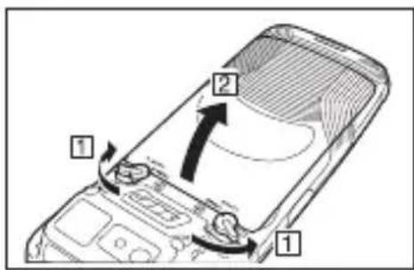
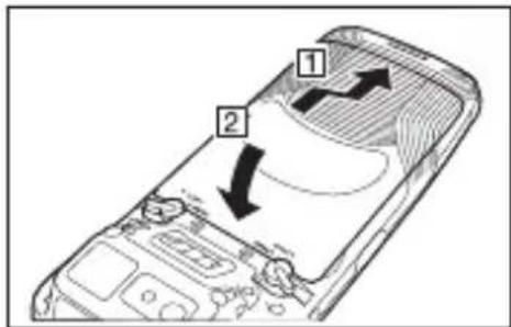
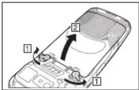
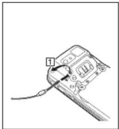
- Turn the terminal over, turn the left and right battery pack cover lock switches to the "FREE" position (1) and remove the battery pack cover (2)
text_image
Diagram of a smartphone interior showing labeled parts and directional arrows indicating motion or movement.If the hand belt is attached
If the hand belt is attached, disengage the hand belt fitting as shown in the illustration.
text_image
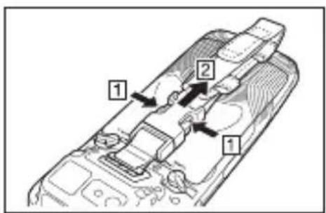
Diagram of a device interior with numbered components and directional arrows indicating flow or movement.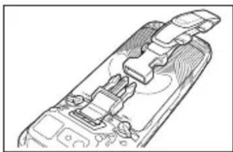
natural_image
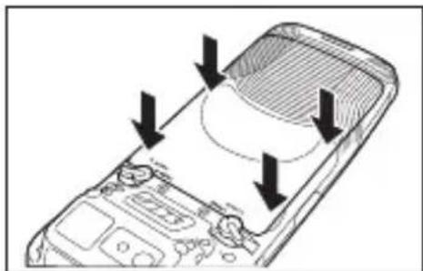
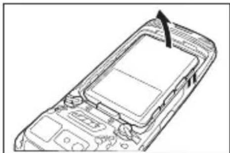
Technical line drawing of a device interior with no visible text or symbols- Install the battery pack in the direction indicated by the arrow.
natural_image
Line drawing of a mobile phone casing with a black arrow pointing to the screen (no text or symbols)- Replace the battery pack cover (☐) as shown in the illustration.
text_image
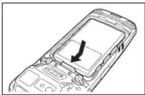
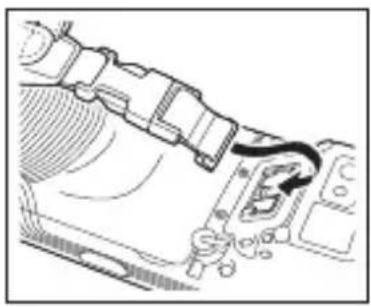
Diagram of a smartphone with labeled parts and directional arrows indicating movement or operation- Press down on the battery pack cover so that it is securely closed.
natural_image
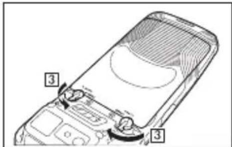
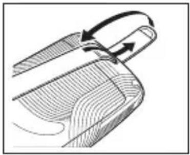
Diagram of a smartphone with a curved screen and directional arrows indicating motion or force (no text or symbols present)- Return the left and right battery pack cover lock switches to the "LOCK" position (B)
text_image
Diagram of a device with labeled parts, showing a screen and adjustment knobs for assembly or repair.Precautions for Use
- Do not use any battery packs other than the specified one.
- The battery pack has a limited service life. Depending on the way the battery pack is charged, its degradation may accelerate or its capacity be reduced so that it cannot be used for as long. If charging the battery pack does not restore its full functionality, this indicates that it has reached the end of its life and should be replaced with a new battery pack of the specified type.
Replacement
- Turn the screen on.
- Hold down the Power key until the Power menu is displayed.
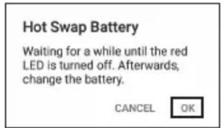
- Tap "Hot swap" as shown in the figure.

text_image
Power off Restart Screenshot Hot swap Hot swap- Tap "OK" as shown in the figure and the terminal will switch to the Hot Swap mode. This causes the notification LED to light red. Once switching is completed, the notification LED turns off.
text_image
Hot Swap Battery Waiting for a while until the red LED is turned off. Afterwards, change the battery. CANCEL OK- Turn the terminal over, turn the left and right battery pack cover lock switches to the "FREE" position (1) and remove the battery pack cover (2)
text_image
Diagram of a smartphone interior showing labeled parts and directional arrows indicating movement or rotation.- Remove the battery pack in the direction indicated by the arrow.
natural_image
Line drawing of a mobile phone casing with an arrow pointing to the top panel (no text or symbols present)- Install the replacement battery pack following steps 2 to 3 of the battery pack installation procedure.
Precautions for Use
- In the Hot Swap mode, even if the battery pack is removed, your work state is saved up to 4 minutes with the memory (RAM) backup function.
The memory (RAM) backup time may decrease depending on the backup battery charging level. - In the Hot Swap mode, the terminal will not respond even if you press the Power key. To exit Hot Swap mode, open the battery cover and then close it again.
- In case of replacing the battery pack without selecting the Hot Swap mode, you cannot perform normal operations for a while.
Installing and Removing the AC Adapter
The AC adapter must be fitted with a suitable power plug for the region where the terminal will be used.
Installation
- Insert the protruding part of the AC adapter plug into the recess in the top of the AC adapter (1) until the plug clicks into place (2)
USB AC adapter AC adapter for USB and Ethernet cradles

text_image
Diagram of a device with labeled parts and directional arrows indicating movement or force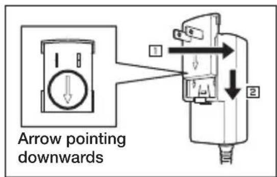
text_image
Arrow pointing downwardsRemoval
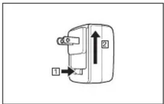
- Push the AC adapter plug release lever in the direction indicated by the arrow in the figure (1) and then pull out the AC adapter plug in the direction of the arrow (2)
USB AC adapter AC adapter for USB and Ethernet cradles
text_image
Diagram of a device with labeled parts and directional arrows, showing components 1 and 2.
text_image
Diagram of a mechanical device with labeled parts and directional arrows indicating movement or forcePrecautions for Use
- Do not insert the plug only into the power outlet.
Charging the Battery Pack
You can charge the battery pack while it is installed in the terminal using the optional USB cradle, Ethernet cradle or multiple battery charger. Check charging status LED to confirm the terminal charging status.
You can also use the USB cradle, Ethernet cradle or dual battery charger to charge the battery pack.
USB Cradle, Ethernet Cradle

text_image
AC Adapter AD-S50400A① Charging the battery pack installed in the terminal
text_image
Diagram of a mobile phone with labeled parts including a keypad, cable, and indicator lightsTerminal charging status LED display
Orange: Charging
Green: Charging complete
Red: Standby due to battery pack error or because the ambient temperature is outside the charging temperature range. (Charging begins when the temperature returns to the charging temperature range.)
Red fl ashing: Charging (The terminal cannot start up because the charge remaining in the battery pack is too low. Wait until the charging status LED stops fl ashing and lights orange.)
② Charging the battery pack
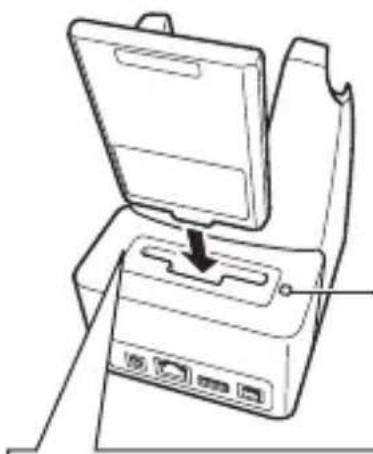
natural_image
Line drawing of a device with an open lid and internal ports, showing a downward arrow indicating a process or operation (no text or symbols present)Cradle charging status (Charging begins when LED
Cradle charging status LED display
Red:
Charging
Green:
Charging
Red/green alternate fl ashing: Standby because the battery pack is faulty, is installed incorrectly or is outside the charging temperature range
temperature returns to the charging temperature range)
As shown in the illustration, insert the battery pack so that the markings on the cradle and battery pack are aligned.

natural_image
Pure technical line drawing of a mechanical component or bracket (no text or symbols)Precautions for Use
• Take care not to trap objects such as the strap in the cradle.
- The power/data communication terminal and the battery pack power contacts should be cleaned periodically using an implement such as a dry cotton bud. Soiling or dust buildup could cause connection problems.
USB AC Adapter
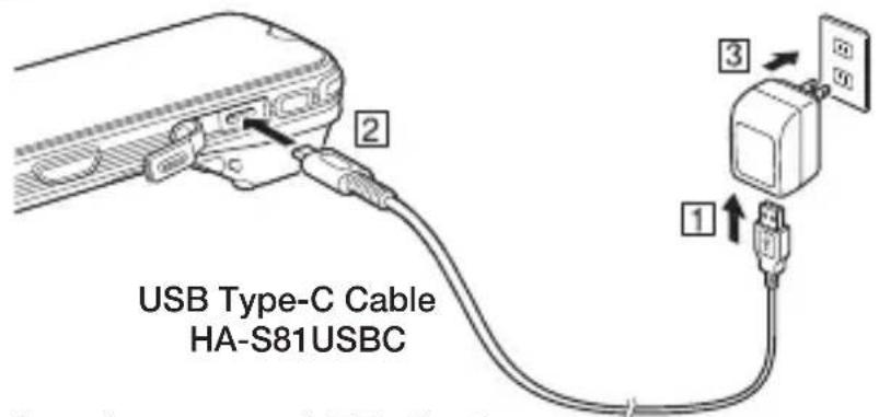
text_image
USB Type-C Cable HA-S81USBCTerminal charging status LED display
Orange: Charging
Green: Charging complete
Red: Standby due to battery pack error or because the ambient temperature is outside the charging temperature range.
(Charging begins when the temperature returns to the charging temperature range.)
Red flashing: Charging (The terminal cannot start up because the charge remaining in the battery pack is too low. Wait until the charging status LED stops flashing and lights orange.)
Multiple Battery Charger

text_image
AD-S12500A- You can connect up to three Multiple Battery Chargers.
Terminal charging status LED display
Orange: Charging
Green: Charging complete
Red: Standby due to battery pack error or because the ambient temperature is outside the charging temperature range.
(Charging begins when the temperature returns to the charging temperature range.)
Red flashing: Charging (The terminal cannot start up because the charge remaining in the battery pack is too low. Wait until the charging status LED stops flashing and lights orange.)
Dual Battery Charger
As shown in the illustration, insert the battery pack so that the markings on the dual battery charger and battery pack are aligned.

natural_image
Pure technical line drawing of a mechanical component without any text, numbers, or symbols
text_image
AD-S12500A- You can connect up to three Dual Battery Chargers.
Charging status LED display for the four-bay battery charger
Red: Charging
Green: Charging complete
Red/green alternate flashing: Standby because the battery pack is faulty, is installed incorrectly or is outside the charging temperature range
(Charging begins when temperature returns to the charging temperature range)
Precautions for Use
• Take care not to trap objects such as the strap in the cradle.
- The power/data communication terminal and the battery pack power contacts should be cleaned periodically using an implement such as a dry cotton bud.
Soiling or dust buildup could cause connection problems.
Using the Stylus Retaining Cord
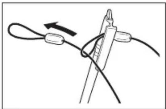
Use the procedure below to attach the stylus retaining cord.
1 Thread the cord through the hole at the top of the stylus.

text_image
Diagram illustrating a cable or cable installation with an arrow indicating direction and an inset showing the detail of the structure.2 Thread the other end of the cord through the loop.
natural_image
Diagram of a rope knot being twisted with a string, showing rope routing and angle (no text or symbols)
natural_image
Medical catheter insertion diagram showing needle placement and cable insertion (no text or labels)Attaching the Neck Strap and Stylus
Use the procedure below to attach the neck strap or stylus to the strap holes.
There are 3 strap holes in the terminal (see pages 13 to 17). Attach the hand strap or stylus in the position that makes it easiest for you to use the terminal.
natural_image
Line drawing of a device with a cable and labeled component (no text or symbols)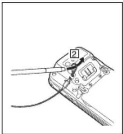
text_image
Diagram showing a cable being inserted into a wire socket with labeled component '2'
text_image
Diagram showing cable installation with labeled component '3' and directional arrows indicating motionThe illustration shows the stylus. Use the same procedure to attach the neck strap.
Precautions for Use
- If you attach the stylus to the strap hole on the barcode reader side of the terminal, take care to keep the stylus and its retaining cord out of the shot when using the camera.
How to attach the Hand Belt
- Push the metal hand belt fi tting so that it engages with the mount on the terminal, as shown in the illustration. Check that the fi tting is securely attached.
natural_image
Technical line drawing of a mechanical assembly with no visible text or symbols- Feed the end of the hand belt through the hand belt mount, fold it back to a suitable length and then fasten it using the hook and loop fastener.
natural_image
Diagram of a mechanical component with curved arrows indicating motion or force direction (no text or symbols)Precautions for Use
- If you are attaching both the hand belt and the neck strap (or stylus), attach the neck strap (or stylus) to the strap hole on the barcode reader side of the terminal.
- Continued use with the hand belt pulled very tight could result in the belt being severed due to friction between the buckle and belt.
- Adjust the hook and loop fastener to a suitable length.
Removing the Hand Belt
- Press on the projecting part of the terminal and disengage the metal hand belt fitting, as shown in the illustration.
- Peel apart the hook and loop fastener and pull the hand belt back through the hand belt mount.

natural_image
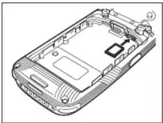
Diagram of a car interior showing a hand inserting a component into a vehicle's seat (no text or symbols present)Using a nanoSIM Card
IT-G600/IT-G650 supports nanoSIM cards.
To use WAN functions, a nanoSIM card must be installed.
The nanoSIM card slot is located in the battery pack compartment, so you must remove the battery pack before installing or removing a nanoSIM card.
Installation
- Turn the terminal off (shutdown).
- Remove the battery pack.
(Steps 5 and 6 in the battery pack replacement procedure on page 21)
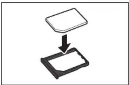
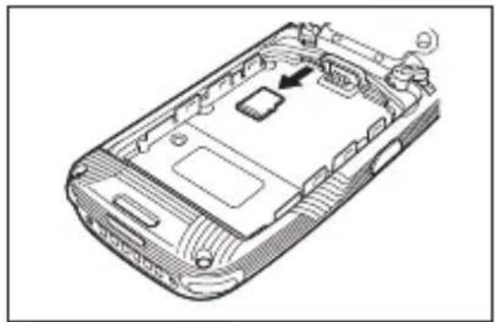
3 Push in the stylus (opposite end) in direction 1 and remove the nanoSIM card tray in direction 2.

text_image
nanoSIM card slot 1 2 Push here with the stylus 1 SIM 2 PUSH RELEASE nanoSIM card tray Push down with the stylus until the tray slides out to the position indicated by the "▲".4 Install the nanoSIM card in the nanoSIM card tray, as shown in the figure.
natural_image
Simple diagram showing a rectangular object being dropped into a rectangular device (no text or symbols)5 Insert the nanoSIM card tray in the direction indicated by the arrow.
natural_image
Technical line drawing of a mobile phone casing with internal components and ventilation slots (no text or symbols)- Install the battery pack.
(Steps 2 and 3 in the battery pack installation procedure on page 19)
Removal
-
Turn the terminal off (shutdown).
-
Remove the battery pack.
(Steps 5 and 6 in the battery pack replacement procedure on page 21)
3 Remove the nanoSIM card tray.
(Step 3 on page 28)
4 Remove the nanoSIM card from the nanoSIM card tray.
5 Install the nanoSIM card tray in the terminal.
- Install the battery pack.
(Steps 2 and 3 in the battery pack installation procedure on page 19)
Precautions for Use
- When installing a nanoSIM card, check the orientation of the card and ensure that you install it correctly. Using excessive force when installing or removing a nanoSIM card could damage the card.
- Touching the contact area when installing a card could result in damage to the card due to soiling or an electrostatic charge.
- When turning off the terminal, be sure to select "Power off" and not "Hot swap".
• Always install the nanoSIM card tray, even when no nanoSIM card is used.
IT-G600/IT-G650 supports micro SD cards.
The microSD card slot is located in the battery pack compartment, so you must remove the battery pack before installing or removing a microSD card.
Installation
- Turn the terminal off (shutdown).
- Remove the battery pack. (Steps 5 and 6 in the battery pack replacement procedure on page 21)
- Push the microSD card into the card slot until it is fully inserted, as shown in the figure.
- Install the battery pack. (Steps 2 and 3 in the battery pack replacement procedure on page 19)

natural_image
Technical line drawing of a mobile phone casing showing internal components and a handle (no text or symbols)Precautions for Use
- The front and back of the card are different, so the card must be oriented correctly when inserted into the slot. Inserting the card incorrectly could damage the card and/or the slot. Take care when inserting cards.
- When turning off the smart handheld terminal, be sure to select “Shutdown” and not “Hot Swap”.
Removal
- Turn the terminal off (shutdown).
- Remove the battery pack. (Steps 5 and 6 in the battery pack replacement procedure on page 21)
- Pull the microSD card out of the card slot, as shown in the figure.
- Install the battery pack. (Steps 2 and 3 in the battery pack replacement procedure on page 19)
natural_image
Technical line drawing of a mobile phone casing with visible internal components and mounting points (no text or symbols)Using the Laser Scaner
-
After turning on the power, position the barcode reader close to a bar code and then press the trigger key.
-
The laser emits light and scans the bar code. If scanning is completed normally, Notification LED displays a green light.

natural_image
Line drawing of a mobile phone with a QR code on top (no text or symbols)Precautions for Use
- If you have problem not properly reading a code, change the angle and/or the distance between the code and the terminal and try reading it again.
- A bar code can be read from a distance of 33mm to 630mm . The actual reading distance depends on the symbology and the resolution.
- Soiling on the barcode reader port may prevent successful reading. Should the reader port become dirty, wipe it clean with a soft and dry cloth.
The NFC is a technology of contactless IC card for short range communication that enables writing data to card and reading data from the card by applying the card close to the NFC Reader.
The integrated NFC can read a contactless IC card used typically for employment identification, etc.
- Hold the card fl at against the NFC reader on the back of the terminal (near the center of the battery cover).

natural_image
Line drawing of a hand holding a smartphone with a card inserted (no text or symbols)Precautions for Use
- Do not apply card while it is overridden by other card. The NFC may not read it correctly.
- A metal object near by the NFC Reader may cause the NFC not to read card correctly. Take the card out of a wallet if the wallet is with metal object before applying it to the NFC Reader.
- Apply card in parallel with the NFC Reader to touch the NFC Reader with the card.
- The NFC reader function in the terminal uses very weak radio waves that do not require a radio station license.
- Frequency band used by the NFC is 13.56 MHz. Secure a sufficient space between the terminal and other reader/writer located in the vicinity. Make sure also that a radio station employs the same frequency band does not locate near by prior to using the terminal.
Making the Touch Panel Easier to Use
You can adjust the sensitivity of your terminal's touch panel. You can choose from 4 levels of touch panel sensitivity: “Wet Touch”, “Normal Touch”, “Comfort Glove Touch” and “Cotton Glove Touch”. If you are finding the touch panel difficult to operate, select the touch panel sensitivity that best suits your situation.
Configuration procedure: “Settings” → “Accessibility” → “Touch Sensitivity”
Circles (○) in the table below denote recommended settings. If you find the touch panel difficult to use with the settings indicated below, try another setting.
| Wet Touch Normal Touch | Comfort Glove Touch | Cotton Glove Touch | ||
| Low Sensitivity High | ||||
| Entry | Finger ( | ○) *1() *2 | ○ | ○ |
| Stylus | ○ | |||
| Thin gloves | ○ | |||
| Thick gloves | ||||
*1 If there are water droplets on the screen or the screen seems too sensitive
*2 If the panel is not sufficiently responsive
Precautions for Use
- If you are wearing gloves or using the stylus, do not select “Wet Touch” even if there is water on the screen.
- If you use the stylus with the optional screen protect sheet on the screen, the screen may seem unresponsive. If this occurs, select “Comfort Glove Touch”.
Turning the Power On/Off and Sleep
Turning the Power On
- Hold down the Power key until the terminal vibrates.
• The startup screen is displayed.
Precautions for Use
- Be sure to completely charge the battery pack before turning the power on for the first time after the purchase.
- If the terminal does not start even after power is turned on, remaining power of the battery pack may be low. Completely charge the battery pack and then turn the power on again.
Turning the Power Off (Shutdown)
-
With the screen displayed, hold down the Power key until the Power menu is displayed.
-
Tap "Power off".
Sleep (Standby)
- Press the Power key with the screen displayed.
- In the sleep state, the screen is turned off, but the terminal remains running.
- Operating state is maintained. Press the Power key and you will be able to use the terminal immediately.
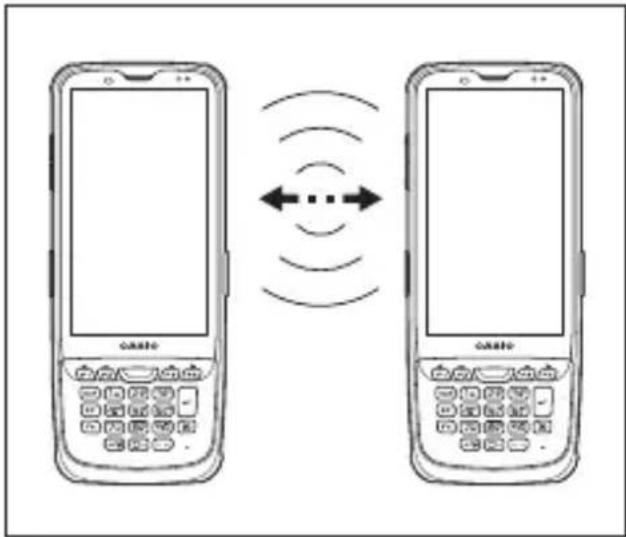
Bluetooth® Communication
Bluetooth ^® interface can also be used to transfer data between two terminals.
With Bluetooth ^® the two terminals should be located within about five meters from each other, as long as there is nothing blocking the path between them.
text_image
Diagram showing two smartphones with 'casto' branding, each connected by a bidirectional signal wave between them.Important!
Observe the following precautions to help ensure that Bluetooth communication is successful.
• Make sure two terminals face each other within five meters. Surroundings (obstacles) between the terminals may cause a shorter distance.
• Make sure there is at least two meters between the terminal and other equipment (electrical appliances, audio-visual equipment, OA equipment, and digital cordless telephones, facsimile machines, etc.). Take special care with microwave ovens. Allow at least three meters between the terminals in wireless operation and a microwave oven. When operating the terminal in Bluetooth nearby these devices and electrical appliances with their powers being turned on, communication may be interrupted or radio receptions may be interfered.
- Normal communication may not be possible in an area near a broadcast trans-mitter or wireless transmitter. If this happens, move the terminal to a different location. Normal communication may not be possible in areas exposed to strong radio waves.
- Interference by WLAN Because Bluetooth ^ and WLAN use the same frequency band (2.4GHz), radio interference can occur if there is a WLAN device nearby. This can result in lower communication speed, or even make it impossible to establish a connection. If this happens, try the following countermeasures.
- Move at least 10 meters away from the WLAN device.
- If you cannot keep the distance at least 10 meters or more between the terminal and a WLAN device, turn off the power of either the terminal or the WLAN device.
- If the terminal's wireless LAN and Bluetooth ^® communication are used at the same time, ambient radio signals may make communication impossible.
Rebooting or Resetting the Terminal
If the terminal no longer operates normally due to a problem such as an operating error or severe impact, use the procedure below to attempt to restore normal operation.
- Reboot
- Forced Reboot
- Reset
Reboot
- With the screen turned on, hold down the Power key until the Power menu is displayed.
- Tap "Reboot".
Forced Reboot
- Hold down the Power key until the terminal vibrates (approx. 12 seconds).
Reset
-
Open the battery cover and remove the battery pack.
-
Hold down the Reset switch. (Approx. 2 seconds)
Tips!
Use the stylus (pen) supplied with the terminal to hold down the Reset switch.
-
Re-install the battery pack and close the battery cover.
-
Turn the power on.
text_image
Stylus Reset switchIT-G600/G650 Specifications
| IT-G600 IT-G650 | Remark | |||||
| -WC01 | -C21-C31-C21-CN | -WC21-WC31 | -C21-C31 | -WC21-WC31 | ||
| CPU Qualcomm 2.2 GHz + 1.8GHz Octa Core | ||||||
| OS Android | TM 9 | |||||
| Memory RAM : 4GB ROM : 64GB | ||||||
| Display | (4.7 inches), 720 × 1280-dot TFT Color LCD | (5.5 inches), 720 × 1440-dot TFT Color LCD | ||||
| Scanner *1 - 2D Scanner (Imager) | ||||||
| Camera 13M pixels | auto focus | |||||
| Microphone Voice and sound | ||||||
| Speaker For voice sound input and voice call at phone | ||||||
| WLAN *2 IEEE 802.11a/b/g/n/ac | ||||||
| Bluetooth® *3 v5.0, EDR/LE | ||||||
| WAN *4 | LTE W-CDMA GSM | - | LTE W-CDMA GSM | - | LTE W-CDMA GSM | |
| GPS *5 GPS, GLON | NASS, BeiDou, QZSS/L1 | |||||
| NFC *6 | Supported cards: ISO1443 Type A, ISO1443 Type B, ISO 15693, FeliCa | |||||
| SD Card Slot | microSDXC card slot × 1 | |||||
| USB | USB 2.0 OTG Type-C × 1 | |||||
| SIM Card Slot | nanoSIM card slot × 1 | - | nanoSIM card slot × 1 | - | nanoSIM card slot × 1 | |
| Main Battery | Lithium-ion battery (rechargeable) | |||||
| Sub battery | Lithium-ion battery (rechargeable) | Not replaceable | ||||
| Operating Period *7 | 20 hours | At room temperature New battery pack | ||||
| Operating Temperature | -20°C ~ 50°C *8 | |||||
| Operating Humidity | 30 ~ 80%RH | |||||
| Drop Durability 1.8m *9 1.5m *9 | ||||||
| Dust / water-resistance | IP67 level | |||||
| External dimensions | Approx. 75mm × 180mm × 18mm | Approx. 78mm × 180mm × 18mm | ||||
| Weight Approx. 295g Approx. 310g | ||||||
| Vibrator Scanner and other notifi cations | ||||||
| Sensors | Proximity sensor / Light Ambient sensor / Acceleration sensor / Geomagnetic sensor / Gyro sensor | |||||
*1
Scanner Specifications
| Item Specification | ||
| 2D Scanner (Imager) | Method CMOS Imager, 1280 × 800, monochrome | |
| Aimer method Laser 650nm, < 1mW | ||
| Laser emit angle | Redirected downward:IT-G600-C21/WC21/C21-CN, IT-G650-C21/WC21: 25 degreeIT-G600-C31/WC31, IT-G650-C31/WC31: 60 degree | |
| Resolution | 1D : 0.127mm2D Stacked : 0.169mm2D Matrix : 0.191mm | |
| PCS 0.45 (minimum) or greater | ||
| Readable distance | 1D : 33 ~ 420mm (0.25mm resolution)1D : 37 ~ 630mm (0.50mm resolution)2D Stacked : 98 ~ 220mm (0.17mm resolution)2D Matrix : 32 ~ 360mm (0.38mm resolution) | |
| Readable width | Max. 32mm (at 33mm depth)Max. 477mm (at 630mm depth) | |
| Focal distance 9.0 inches | ||
| Daylight for scanning | 50,000 Lux or less | |
| Readable 1D symbologies | UPC-A/UPC-E/EAN8 (JAN8)/EAN13 (JAN13)/Codabar (NW-7)/Code39/Interleaved2of5 (ITF)/MSI/ISBT/Code93/Code128/GS1-128 (EAN128)/GS1 DataBar Omnidirectional (RSS-14)/GS1 DataBar Limited (RSS Limited)/GS1 DataBar Expanded (RSS Expanded)/Code32/GS1 DataBar Truncated (RSS-14) | |
| Readable Stacked 2D symbologies | PDF417/Micro PDF/Composite/Codablock F/GS1 DataBar Stacked Omnidirectional (RSS-14 Stacked)/GS1 DataBar Expanded Stacked (RSS Expanted Stacked)/GS1 DataBar Stacked (RSS-14 Stacked)/GS1 DataBar Truncated Stacked (RSS-14) | |
| Readable Matrix 2D symbologies | Aztec/DataMatrix/Maxicode/QR Code/Micro QR/HanXin Code | |
*2
WLAN Spefi cications
| Item Specification | Remark | ||
| WLAN802.11a/b/g/n/ac Frequency | Range | 2412 MHz – 2472 MHz (1 ~ 13ch)5180 MHz – 5320 MHz (36 ~ 64ch)5500 MHz – 5700 MHz (100 ~ 140ch)5745 MHz – 5825 MHz (149 ~ 165ch)(802.11d: Allowed frequency range can be used according to countries or regions.) | |
| Baud rate | 802.11a/g: 54Mbps (maximum)802.11b: 11Mbps (maximum)802.11n HT20 (2.4&5GHz): 72Mbps (maximum)802.11ac : 433Mbps (maximum) | ||
| Communication Distance | Communication Distance 802.11b/g/n: Indoor 50m, Outdoor 150m (n: 2.4GHz)802.11a/n/ac: Indoor 30m, Outdoor 150m (n: 5GHz) | It can change due to surrounding environment | |
*3
Bluetooth ^® Speci cications
| Item Specification | Remark | ||
| Bluetooth® | Frequency Range | 2402 MHz ~ 2480 MHz | |
| Communication Distance | Approx. 5m | It can change due to surrounding environment | |
*4
Wireless WAN Specifications
Item Specification
| LTE | Communication | Audio, Data Packet |
| Baud rate | Downlink: 150Mbps (maximum)Uplink: 50Mbps (maximum) | |
| FDD 1 (1920-1980MHz/2110-2170MHz)FDD 3 (1710-1785MHz/1805-1880MHz)FDD 7 (2500-2570MHz/2620-2690MHz)FDD 8 (880-915MHz/925-960MHz) | ||
| Frequency range Band | FDD 19 (830-845MHz/875-890MHz)FDD 20 (832-862MHz/791-821MHz)FDD 26 (814-849MHz/859-894MHz)TDD 38 (2570-2620MHz/2570-2620MHz)TDD 39 (1880-1920MHz/1880-1920MHz)TDD 41 (2496-2690MHz/2496-2690MHz) | |
| W-CDMA | Communication | Audio, Data Packet |
| Baud rate | Downlink: 42Mbps (maximum)Uplink: 11Mbps (maximum) | |
| Frequency range Band | BAND 1 (1920-1980MHz/2110-2170MHz)BAND 6 (830 - 840MHz/875 - 885MHz)BAND 8 (880-915MHz/925-960MHz) | |
| GSM | Communication | Audio, Data Packet |
| Protocol GSM/GPRS/EDGE | ||
| Frequency range Band | EGSM900 (880-915 MHz/925-960 MHz)DCS1800 (1710-1785 MHz/1805-1880 MHz) | |
*5
GPS Speci cications
Item Specification
| GPS | WAN and GNSS modes | Simultaneous-GNSS (WAN+GNSS at the same time) Standalone-GNSS (without WAN) A-GPS |
| Protocol | NMEA | |
| Sensitivity | Acquisition sensitivity: -145 dBmTracking sensitivity: -158 dBm |
*6
NFC Spefi cications
| Item Specification | Remark | ||
| NFC | Depth of Field | ISO14443 Type A/B, FeliCa:0 mm (Contact) | It can change by the design of Card or Tag |
| ISO15693:0 mm (Contact) ~ 50 mm (Maximum) | |||
*7
According to JEITA G mode
LCD backlight brightness minimum, WLAN ON (with stable RF connection), Buzzer minimum, Vibrator OFF, RF OFF (except for WLAN), Power saving setting after scanning (1sec)
*8
- Camera Flash is unavailable in -20^ -11^ .
- Battery pack charge operation: 0 40^ C
Charging stops if the battery pack's internal temperature is 0 °C or below or 40 °C or above.
*9
The drop durability height is a measured value resulting from actual testing. It does not necessarily guarantee the product from damage
USB Cradle (HA-U60IO)
The USB cradle can be used to connect the IT-G600/IT-G650 to devices such as a computer or USB device. It can also be used to supply power to the IT-G600/IT-G650 and to charge the battery pack.
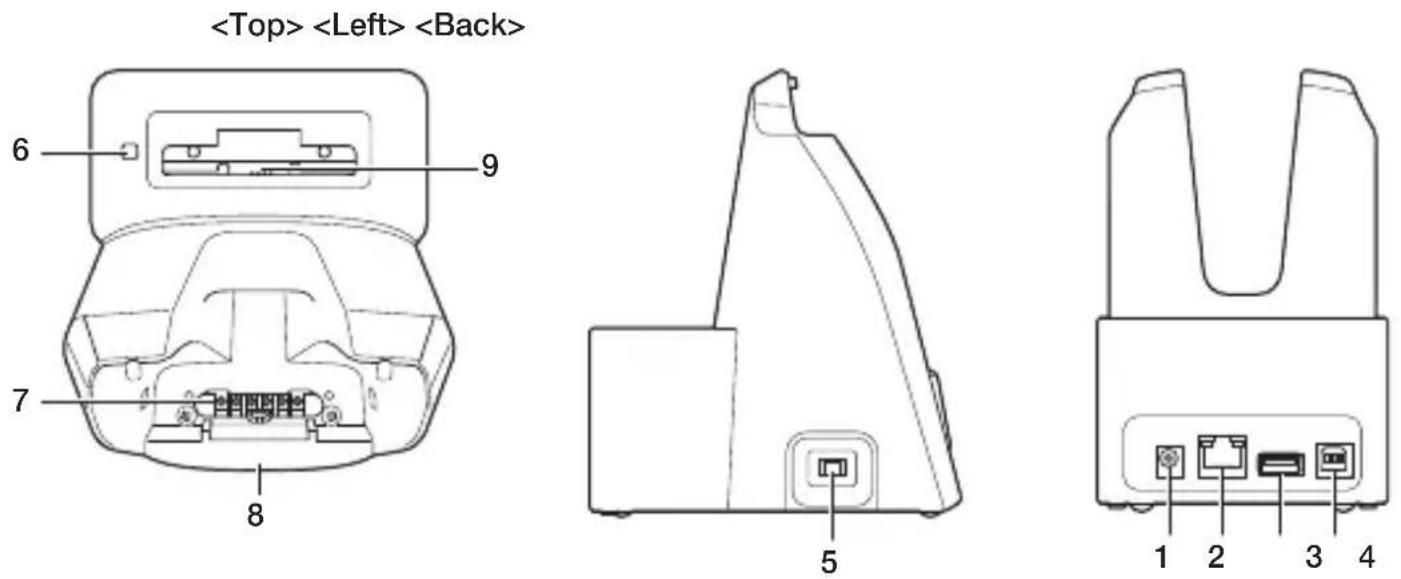
Part Names and Operation
text_image
3 6 4 5
natural_image
Line drawing of a mechanical component or bracket (no text or symbols)
natural_image
Diagram of a device rear panel with two labeled ports (no text or symbols beyond labels)| 1 AC Adaptor Jack Used to connect an | AC adapter as a power supply. |
| 2 USB Client Port Used to connect to a computer. | |
| 3 Charging Status LED(Battery Pack) | Shows the charging status.Red: ChargingGreen: Charging completeFlashing alternately red/green: Battery pack fault or outside charging temperature range |
| 4 Power Supply/Data Communication Terminal | Used to supply power to the IT-G600/IT-G650 or for data communication. |
| 5 Mounting Status LED | Indicates the mounting status of the IT-G600/IT-G650.Red: IT-G600/IT-G650 is not installed.Green: IT-G600/IT-G650 mounted correctly. |
| 6 Battery Pack Charging Terminals Used to charge the battery pack. | |
Installing and Connecting the Power Supply
Use the optional AC adaptor(AD-S50400A) to supply power to the charger.
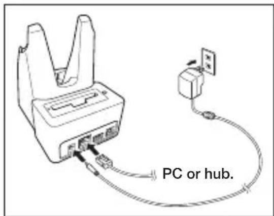
- Plug the AC adapter into the AC adapter jack on the back of the USB cradle.
- Plug the AC adapter into a mains power outlet.
- When connecting to a computer, plug the USB cable into the USB client port.
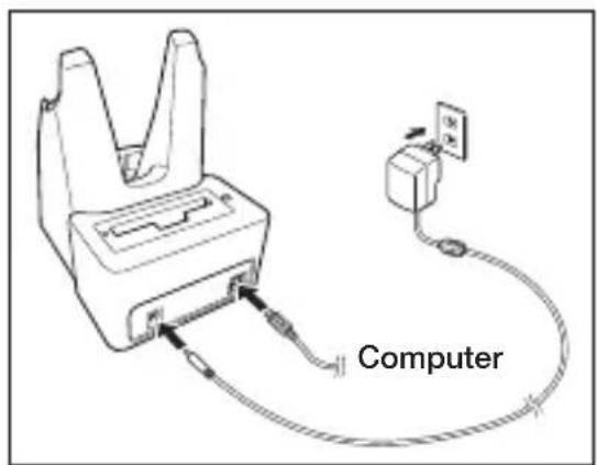
text_image
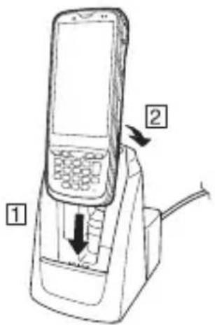
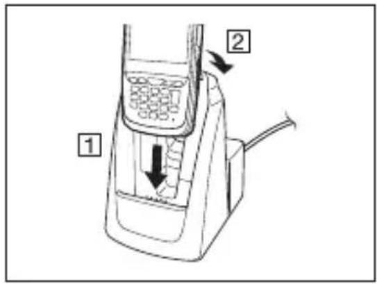
Computer- Align the terminals on the bottom of the IT-G600/IT-G650 with the power supply terminals in the USB Cradle before inserting the IT-G600/IT-G650 (1). Push the IT-G600/IT-G650 fully into the USB Cradle until the mount hooks in the cradle engage the mount holes in the IT-G600/IT-G650 (2).
To remove the IT-G600/IT-G650 from the USB Cradle, tilt the IT-G600/IT-G650 forward to disengage the mount hooks from the mount holes and then lift the IT-G600/IT-G650 out of the cradle.
text_image
Diagram of a mobile phone device with labeled parts and directional arrows indicating internal components.Precautions for Use
- Even if the battery in the IT-G600/IT-G650 is already fully charged, charging will begin when you set the IT-G600/IT-G650 in the USB cradle. It may take several minutes for the fully charged status to be indicated.
- In high- or low-temperature environments, charging may be restricted to protect the battery pack. At such temperatures, the level of battery charge may not reach 100% even when the charging status LED is green and charging is completed.
- Water or other moisture on the power contacts could cause sparking or an electric shock, and soiled contacts could block the connection and impair charging functionality. To ensure safety, clean the power contacts by wiping them off with a dry cloth or cotton bud after you disconnect the AC adapter.
- When disconnecting the AC adapter from the mains power outlet and IT-G600/IT-G650, do so by gripping the connector and not by pulling on the cord.
USB Cradle (HA-U60IO) Specifications
1. USB specifications
Standard : USB 2.0 High Speed Transmission speed : 480 Mbps (maximum)
2. Charging specifications
Charging method : Constant-voltage constant-current charging Charging time : Approx. 4 hours
3. AC adapter specifications
Standard : AD-S50400A Input : 100-240V AC, 50/60Hz, 0.7A Output : 5V DC, 4A
4. Dimensions, weight
Dimensions : Approx. 137(W) × 102(D) × 162(H) mm Weight : Approx. 394g
5. Operating environment
Operating temperature : 0°C to 40°C Operating humidity : 30-80% RH (condensation-free)
Ethernet Cradle (HA-U62IO)
The optional Ethernet Cradle (HA-U62IO) makes it possible to transmit file data between IT-G600/IT-G650 and a PC via a USB or LAN connection (download or upload). You can also use the Ethernet Cradle to charge the battery pack installed in IT-G600/IT-G650. It can also be used to connect the IT-G600 and IT-G650 to a computer or USB device.
Part Names and Operation
| 1 AC Adaptor Jack Used to connect an | AC adapter as a power supply. |
| 2 LAN Port | Used to connect and transfer data to a computer or hub via a LAN cable for data transfer. |
| 3 USB Host Port Used to connect a corresponding USB peripheral device. | |
| 4 USB Client Port Used to connect to a computer. | |
| 5 Selector Switch | Used to switch between a USB connection and a LAN connection.LAN: LANA: USB hostB: USB client |
| 6 Charging Status LED(Battery Pack) | Shows the charging status.Red: ChargingGreen: Charging completeFlashing alternately red/green: Battery pack fault or outside charging temperature range |
| 7 Power Supply/Data Communication Terminal | Used to supply power to the IT-G600/IT-G650 or for data communication. |
| 8 Mounting Status LED | Indicates the mounting status of the IT-G600/IT-G650.Red: IT-G600/IT-G650 is not installed.Green: IT-G600/IT-G650 mounted correctly. |
| 9 Battery Pack Charging Terminals Used to charge the battery pack. | |
Installing and Connecting the Power Supply
Use the optional AC adaptor(AD-S50400A) to supply power to the charger.
Use the selector switch on the left side of the Ethernet Cradle to select the port to be used. Set the switch to the “LAN” position when using the LAN port on the cradle. Set the switch to the “B” position when using the unit as a USB client, or set it to the “A” position when using the unit as a USB host.

text_image
LAN A B-
Plug the AC adapter into the AC adapter jack on the back of the Ethernet Cradle.
-
Plug the AC adapter into a mains power outlet.
-
When using a LAN, plug the LAN cable into the LAN port and then connect the cable to the computer or to a hub.
text_image
PC or hub.- Align the terminals on the bottom of the IT-G600/IT-G650 with the power supply terminals in the Ethernet Cradle before inserting the IT-G600/IT-G650 (1). Push the IT-G600/IT-G650 fully into the Ethernet Cradle until the mount hooks in the cradle engage the mount holes in the IT-G600/IT-G650 (2).
To remove the IT-G600/IT-G650 from the Ethernet Cradle, tilt the IT-G600/IT-G650 forward to disengage the mount hooks from the mount holes and then lift the IT-G600/IT-G650 out of the cradle.

text_image
Diagram of a mobile phone with labeled parts and directional arrows indicating movement or operationPrecautions for Use
- Even if the battery in the IT-G600/IT-G650 is already fully charged, charging will begin when you set the IT-G600/IT-G650 in the Ethernet cradle. It may take several minutes for the fully charged status to be indicated.
- In high- or low-temperature environments, charging may be restricted to protect the battery pack. At such temperatures, the level of battery charge may not reach 100% even when the charging status LED is green and charging is completed.
- Water or other moisture on the power contacts could cause sparking or an electric shock, and soiled contacts could block the connection and impair charging functionality. To ensure safety, clean the power contacts by wiping them off with a dry cloth or cotton bud after you disconnect the AC adapter.
- When disconnecting the AC adapter from the mains power outlet and IT-G600/IT-G650, do so by gripping the connector and not by pulling on the cord.
Ethernet Cradle (HA-U62IO) Specifications
1. LAN specifications
Communications method : IEEE 802.3-compliant
Media type : 10base-T/100base-TX auto switched
2. Charging specifications
Charging method : Constant-voltage constant-current charging
Charging time : Approx. 4 hours
3. AC adapter specifications
Standard : AD-S50400A
Input : 100-240V AC, 50/60 Hz, 0.7A
Output : 5V DC, 4A
4. Dimensions, weight
Dimensions : Approx. 137(W) × 102(D) × 162(H) mm
Weight : Approx. 405g
5. Operating environment
Operating temperature : 0^ C to 40^ C
Operating humidity : 30-80% RH (condensation-free)
Multiple Battery Charger (HA-U36DCHG)
The optional Multiple Battery Charger (HA-U36DCHG) can concurrently charge two battery packs installed in IT-G600 and/or IT-G650 terminals.
Part Names and Operation
text_image
text_image
5 6
natural_image
Simple line drawing of a mechanical or electrical component with no text, numbers, or symbols
text_image

text_image
Diagram of a device with labeled parts 1 and 2, showing internal components and connections.Accessories
Use these bundled items to join multiple chargers together.
- Bottom bracket
- Side bracket

natural_image
Simple line drawing of a rectangular electronic component with two internal slots and a base (no text or symbols)
- Screws (for brackets) Two each for one bracket
| 1 AC Adaptor Jack Connect the AC adaptor (sold separately) here. | ||
| 2 Power Switch Turns the power on and off. | ||
| 3 | Multiple Battery Charger Connection Port | Use these connectors to connect Multiple Battery Chargers to each other. |
| 4 | Connection Bracket Attachment Holes | Used to connect Multiple Battery Chargers to each other. |
| 5 Power Contacts Power is supplied to the IT-G600/IT-G650 via these contacts. | ||
| 6 Power LED | This LED indicates the power status and the mounting status of the IT-G600/IT-G650.Off: Power offRed: Power on, IT-G600/IT-G650 not mountedGreen: Power on, IT-G600/IT-G650 mounted correctly | |
Charging Battery Pack
Use the optional AC adaptor(AD-S12500A) to supply power to the charger.

text_image
AD-S12500A- Plug the connector from the AC adaptor into the AC adaptor jack on the charger with the engraved side of the connector facing upwards. Push the connector firmly into the jack until it clicks into place.
- After connecting the power cable to the AC adaptor, plug the other end of it into an AC outlet.
- Turn on the power switch on the side of the charger. The power LEDs on the top of the charger light red.
- Place IT-G600/IT-G650 in the charger as illustrated so that the terminals on the bottom of the IT-G600/IT-G650 make contact with the power contacts of the charger. Take care not to trap objects such as the strap in the charger.
The power LEDs on the top of the charger light green and Charging Status LED lights orange.
IT-G600/IT-G650 Charging status LED display
Orange: Charging
Green: Charging complete
Red: Standby due to battery pack error or because the ambient temperature is outside the charging temperature range.
(Charging begins when the temperature returns to the charging temperature range.)
Red flashing: Charging (IT-G600/IT-G650 cannot start up because the charge remaining in the battery pack is too low. Wait until the charging status LED stops flashing and lights orange.)
Precautions for Use
- Even if the battery in the IT-G600/IT-G650 is already fully charged, charging will begin when you set the IT-G600/IT-G650 in the Ethernet cradle. It may take several minutes for the fully charged status to be indicated.
- Water or other moisture on the power contacts could cause sparking or an electric shock, and soiled contacts could block the connection and impair charging functionality. To ensure safety, clean the power contacts by wiping them off with a dry cloth or cotton bud after you disconnect the AC adapter.
- Do not unplug the AC adaptor from the charger while charging battery packs continues.
- When disconnecting the AC adapter from the mains power outlet and IT-G600/IT-G650, do so by gripping the connector and not by pulling on the cord.
- When placing the IT-G600/IT-G650 into the charger, take care not to trap the pen cord or neck strap in the charger. Pull the hand strap out as shown in the illustration.
- Place the Multiple Battery Charger on a flat, level surface and take care when placing the IT-G600/IT-G650 in or removing it from the cradle.
Connecting Multiple Battery Chargers
You can connect up to three Multiple Battery Chargers. Doing so makes it possible to supply power to all the Multiple Battery Chargers using one dedicated AC adaptor.
- As shown in the illustrations below, remove the connector covers of the Multiple Battery Chargers you want to connect to each other.
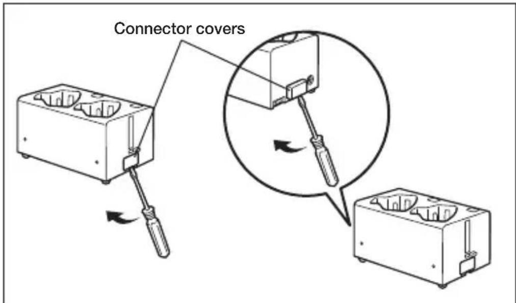
text_image
Connector covers- Connect the two Multiple Battery Chargers as shown below.
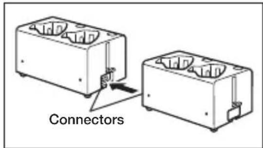
text_image
Connectors- Fix the side and bottom brackets in place with two screws on each bracket. You can repeat the above steps to connect up to 3 Multiple Battery Chargers. * Attach the connection brackets so that the front side faces outwards. (The front side has protruding ribs.)

text_image
Brackets Rib Side Bottom RibPrecautions for Use
• Each unit of the charger comes with one piece each of the side and bottom brackets. After you join two chargers together using these two brackets, one side bracket and one bottom bracket will be left over. Keep these as spare for use in future.
- Always disconnect the AC adaptor before joining multiple chargers together.
Specifications
1. Charging specifications
Charging method : Constant-voltage constant-current charging
Charging time : Approx. 4 hours
2. AC adapter specifications
Standard : AD-S12500A
Input : 100-240V AC, 50/60 Hz, 1.5A
Output : 12V DC, 5A
3. Dimensions, weight
Dimensions : Approx. 172(W) × 100(D) × 83(H) mm
Weight : Approx. 483g
4. Operating environment
Operating temperature : 0°C to 40°C
Operating humidity : 30-80% RH (condensation-free)
Dual Battery Charger (HA-U32DCHG)
The optionally available Dual Battery Charger (HA-U32DCHG) can be used to simultaneously charge two battery packs.
Part Names and Operation
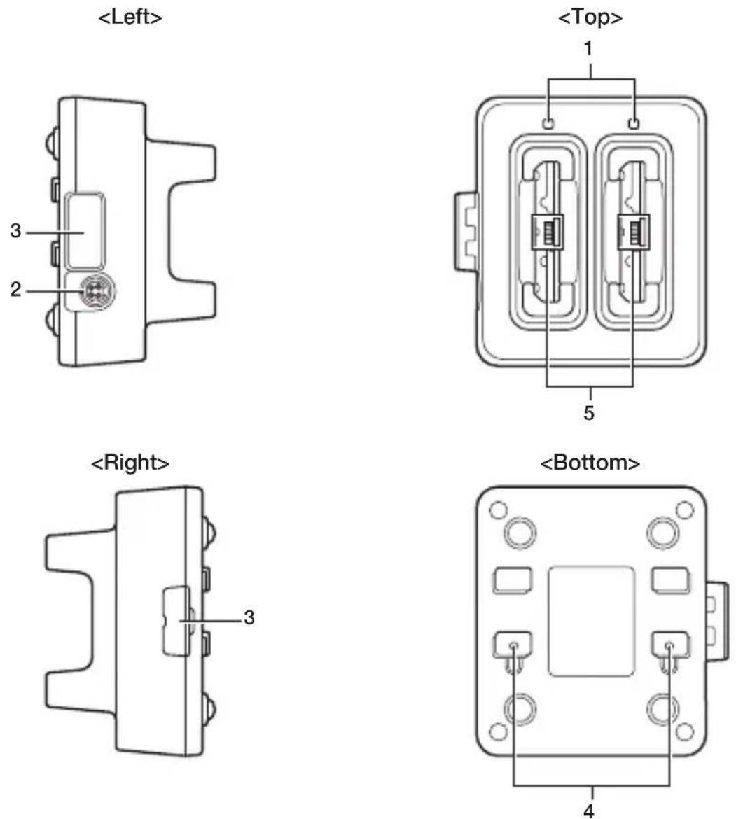
Accessories
Use these bundled items to join multiple chargers together.
- Bottom bracket
- Screws (two for brackets)
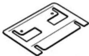
natural_image
Simple line drawing of a rectangular electronic component with two slots and a handle (no text or symbols)
| 1 Charging Status LED | Off: The battery pack is not installed.Red: ChargingGreen: Charging completeRed/green alternate flashing: Standby because the battery pack is faulty, is installed incorrectly or is outside the charging temperature range(Charging begins when temperature returns to the charging temperature range) |
| 2 AC Adaptor Jack Connect the AC adaptor (sold separately) here. | |
| 3 Dual Battery Charger Connection Port | Used to connect Dual Battery Chargers to each other. |
| 4 Connection Bracket Attachment Holes | The connection bracket attaches here when you connect Dual Battery Chargers to each other. |
| 5 Battery Pack Contacts Used to charge the battery pack. | |
Precautions for Use
- Water or moisture on the power contacts can cause a short-circuit and/or fire. Soil on the power contacts will deteriorate the conduction causing poor charge performance. When cleaning the power contacts, unplug the AC adaptor from the charger as safety precaution and wipe off soil on the power contacts with a dry and soft cloth or with cotton swab.
- The battery packs may become warm during charging. This is normal and does not indicate a fault.
- Do not cover or place objects on top of the battery charger during charging.
- Do not remove batteries or disconnect the AC adapter during charging.
• Repeatedly installing and removing rechargeable batteries can cause them to deteriorate. - One connection attachment is provided for each dual battery charger. When multiple dual battery chargers are connected, one connection attachment will be spare. The spare connection attachment can be used as a backup.
Charging Battery Pack
Use the separately sold AC adaptor (AD-S12500A) for the power supply of the Dual Battery Charger.
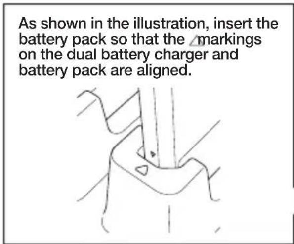
text_image
As shown in the illustration, insert the battery pack so that the markings on the dual battery charger and battery pack are aligned.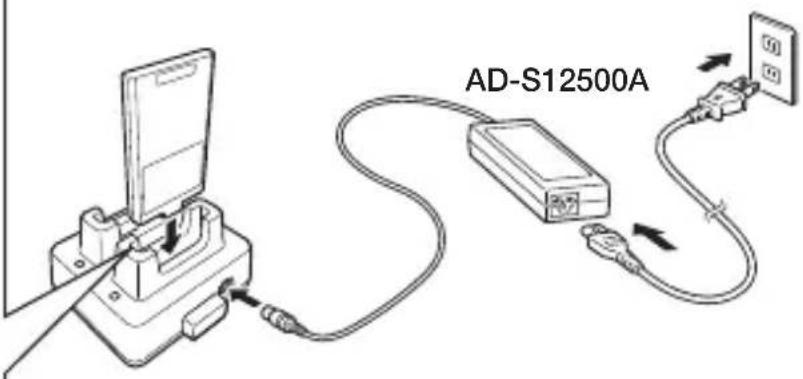
text_image
AD-S12500A- Plug the cord from the AC adaptor into the AC adaptor jack of the Dual Battery Charger.
- Plug the AC cord into a wall outlet.
- Taking care that the battery pack is oriented correctly, insert it into the Dual Battery Charger. This causes the Charge Indicator LED to light in red, indicating that charging has started.
Charging status LED display for the four-bay battery charger
Off: The battery pack is not installed.
Red: Charging
Green: Charging complete
Red/green alternate flashing: Standby because the battery pack is faulty, is installed incorrectly or is outside the charging temperature range
(Charging begins when temperature returns to the charging temperature range)
Connecting Multiple Dual Battery Chargers
You can connect up to three Dual Battery Chargers. Doing so makes it possible to supply power to all the Dual Battery Chargers using one dedicated AC adaptor.
- As shown in the illustrations below, remove the connector covers of the Dual Battery Chargers you want to connect to each other.

text_image
Connector covers- Connect the two Dual Battery Chargers as shown below.
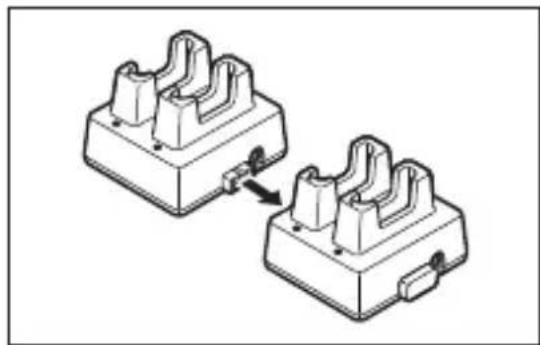
natural_image
Two identical mechanical component blocks with internal channels and mounting holes, connected by a cable (no text or symbols visible)- Turn over the connected Dual Battery Chargers and attach a connection bracket, securing it in place with screws.
You can repeat the above steps to connect up to 3 Dual Battery Chargers.
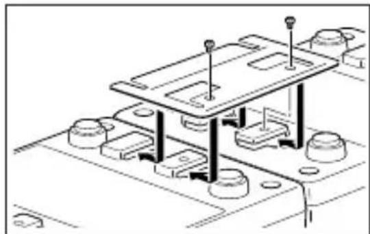
natural_image
Technical line drawing of a mechanical assembly with mounting holes and structural supports (no text or symbols)Specifications
1. Charging specifications
Charging method : Constant-voltage constant-current charging
Charging time : Approx. 4 hours
2. AC adapter specifications
Standard : AD-S12500A
Input : 100-240V AC, 50/60 Hz, 1.5A
Output : 12V DC, 5A
3. Dimensions, weight
Dimensions : Approx. 104(W) × 114(D) × 71(H) mm
Weight : Approx. 205g
4. Operating environment
Operating temperature : 0°C to 40°C
Operating humidity : 30-80% RH (condensation-free)
USB Type-C Cable (HA-S81USBC)
The USB Type-C cable can be used to connect the IT-G600/IT-G650 to a computer. It can also be used to supply power to the IT-G600/IT-G650.
Connecting to a computer
- Connect the USB Type-C cable to the USB Type-C port on the IT-G600/IT-G650.
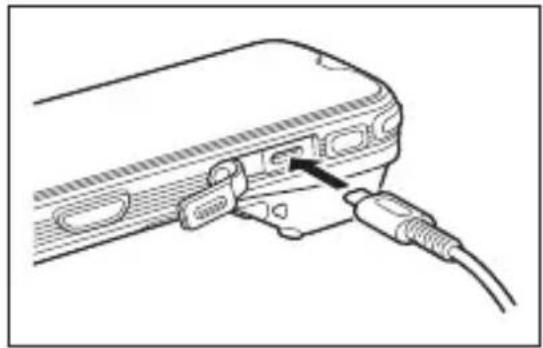
natural_image
Line drawing of a device with a USB cable inserted into a connector (no text or symbols)Precautions for Use
- Water or other moisture on the IT-G600/IT-G650 and USB Type-C cable power supply/data communication terminal could cause sparking or an electric shock, and soiling on the terminal could block the connection and impair charging functionality. To ensure safety, disconnect the AC adapter and USB cable and then clean the power contacts by wiping them off with a dry cloth or cotton bud.
- Never short-circuit the IT-G600/IT-G650 and the USB cable power supply/data communication terminal as this could cause a fault.
HA-U20BAT

natural_image
Two technical line drawings of electronic components, one with a slot and the other with a circular hole (no text or symbols)Precautions for Use
- Store a battery pack in its special soft case whenever you are not using it.
- If the battery pack has been left over unused for a long period of time, the capacity remained decreases due to spontaneous discharge or chemical decomposition by the battery pack itself. If the battery pack fails to hold its operating duration after it has been fully charged, replace it with a new one. The battery pack may reach the end of its service life.
- When buying a battery pack, you should purchase a Casio genuine battery pack.
Battery Pack Specifications
Model: HA-U20BAT
Rated Capacity: 3000mAh/11.4Wh
Rated Voltage: 3.8V
Dimensions: Approx. 89(W) × 57(D) × 8(H) mm
Weight: Approx. 67g
Bundled Item: Soft case
CASIO®
CASIO COMPUTER CO., LTD.
6-2, Hon-machi 1-chome
Shibuya-ku, Tokyo 151-8543, Japan