
WGXB102 - Powerline Adapter NETGEAR - Free user manual and instructions
Find the device manual for free WGXB102 NETGEAR in PDF.

| Product Type | 54 Mbps Wall-Plugged Wireless Range Extender Kit (Powerline + Wireless) |
| Model Number | WGXB102 |
| Power Supply | AC 100-120V, 110mA, 50-60Hz (each unit) |
| Wireless Standard | IEEE 802.11g (up to 54 Mbps), backward compatible with 802.11b |
| Powerline Standard | HomePlug 1.0 (up to 14 Mbps) |
| Security | WEP 64/128-bit, WPA-PSK, MAC address filtering, powerline network password (HomePlug encryption) |
| Operating Modes | Access Point Mode (default), Router Mode (with NAT and DHCP) |
| Indicators | LEDs: Power, HomePlug/Internet, Wireless (WGX102); Power, HomePlug, Ethernet (XE102) |
| Connectors | XE102: Ethernet RJ-45; WGX102: Powerline (built-in), wireless antenna (internal) |
| Package Contents | WGX102 wireless unit, XE102 Powerline Ethernet bridge, Ethernet cable, Resource CD, installation guide, warranty card |
| Management | Web-based configuration utility (HTTP), Windows configuration utility (CD), firmware upgrade via web |
| Wireless Features | SSID broadcast control, channel selection (1-11), multiple SSID support, wireless client isolation |
| Powerline Features | Unique device passcode (PWD) for network password assignment, encryption always enabled |
| Maintenance | Backup/restore configuration, factory reset button (bottom panel), firmware upgrade |
| Compliance | FCC Class B, CE |
| Warranty | 90 days free technical support (phone/email); standard product warranty |
| Environment | Indoor use only |
Frequently Asked Questions - WGXB102 NETGEAR
User questions about WGXB102 NETGEAR
0 question about this device. Answer the ones you know or ask your own.
Ask a new question about this device
Download the instructions for your Powerline Adapter in PDF format for free! Find your manual WGXB102 - NETGEAR and take your electronic device back in hand. On this page are published all the documents necessary for the use of your device. WGXB102 by NETGEAR.
USER MANUAL WGXB102 NETGEAR
Reference Manual for the 54 Mbps Wall-Plugged Wireless Range Extender Kit WGBX102

natural_image
Two silver NETGEAR audio jack devices shown from different angles (no text or symbols visible on the devices themselves)NETGEAR
NETGEAR, Inc. 4500 Great America Parkway Santa Clara, CA 95054 USA
202-10119-01 v1.0 Version 1.0 July 2005
© 2005 by NETGEAR, Inc. All rights reserved. July 2005.
Trademarks
NETGEAR is a trademark of Netgear, Inc.
Microsoft, Windows, and Windows NT are registered trademarks of Microsoft Corporation.
Other brand and product names are registered trademarks or trademarks of their respective holders.
Statement of Conditions
In the interest of improving internal design, operational function, and/or reliability, NETGEAR reserves the right to make changes to the products described in this document without notice.
NETGEAR does not assume any liability that may occur due to the use or application of the product(s) or circuit layout(s) described herein.
Federal Communications Commission (FCC) Compliance Notice: Radio Frequency Notice
This equipment has been tested and found to comply with the limits for a Class B digital device, pursuant to part 15 of the FCC Rules. These limits are designed to provide reasonable protection against harmful interference in a residential installation. This equipment generates, uses, and can radiate radio frequency energy and, if not installed and used in accordance with the instructions, may cause harmful interference to radio communications. However, there is no guarantee that interference will not occur in a particular installation. If this equipment does cause harmful interference to radio or television reception, which can be determined by turning the equipment off and on, the user is encouraged to try to correct the interference by one or more of the following measures:
- Reorient or relocate the receiving antenna.
- Increase the separation between the equipment and receiver.
- Connect the equipment into an outlet on a circuit different from that to which the receiver is connected.
- Consult the dealer or an experienced radio/TV technician for help.
Certificate of the Manufacturer/Importer
It is hereby certified that the 54 Mbps Wall-Plugged Wireless Range Extender Kit WGBX102 has been suppressed in accordance with the conditions set out in the BMPT-AmtsblVfg 243/1991 and Vfg 46/1992. The operation of some equipment (for example, test transmitters) in accordance with the regulations may, however, be subject to certain restrictions. Please refer to the notes in the operating instructions.
Federal Office for Telecommunications Approvals has been notified of the placing of this equipment on the market and has been granted the right to test the series for compliance with the regulations.
Product and Publication Details
Model Number: WGXB102
Publication Date: July 2005
Product Family: router
Product Name: 54 Mbps Wall-Plugged Wireless Range Extender Kit WGBX102
Home or Business Product: home
Language: English
Contents
Chapter 1
About This Manual
Audience, Scope, Conventions, and Formats 1-1
How to Use This Manual 1-2
How to Print this Manual 1-2
Chapter 2
Introduction
Key Features 2-1
802.11g Wireless Networking 2-2
Easy Installation and Management 2-2
Content Filtering in Router Mode 2-3
Maintenance and Support 2-3
Package Contents 2-3
Connectors, Reset Buttons, Ports, and Label Information 2-4
The WGX102 Wireless Unit 2-4
The Label on the Rear Panel of the WGX102 2-5
The WGX102 Bottom Panel 2-5
The XE102 Wall-Plugged Ethernet Bridge 2-6
The Label on the Rear Panel of the XE102 2-7
Chapter 3
Installing the Wireless Range Extender Kit
How the Wireless Range Extender Fits in Your Network 3-1
Prepare to Install Your Wireless Range Extender 3-2
Default Factory Settings ....3-2
First, Set Up the Powerline Network ....3-3
Now, Add the WGX102 to Your Wireless Network 3-5
Plug and Play Installation 3-6
Custom WGX102 Setup 3-7
Test Your Wireless Connectivity ....3-9
Contents v
Basic Installation Troubleshooting Tips ....3-9
Logging On to Configure the WGX102 3-10
Using the WGX102 Configuration Utility 3-12
Configuring the LAN IP Setup Options in Access Point Mode 3-16
Chapter 4
Powerline Network Configuration and Security
Understanding How the Powerline Network Password Works 4-1
Configuring the Powerline Network Password 4-2
Chapter 5
Wireless Configuration and Security
Observing Performance, Placement, and Range Guidelines ....5-1
Implementing Appropriate Wireless Security 5-2
Wireless Data Security Options 5-2
Understanding Basic Wireless Settings 5-2
Information to Gather Before Changing Basic Wireless Settings 5-5
Default Factory Settings 5-6
Setting Up and Testing Basic Wireless Connectivity 5-7
WEP Security Options 5-9
WPA-PSK Wireless Security Options 5-11
Access List: Restricting Wireless Access by MAC Address 5-12
Chapter 6
Maintenance
Changing the Administrator Password 6-1
Viewing Access Point Status Information 6-2
Viewing Router Status Information 6-5
Viewing a List of Attached Devices 6-8
Configuration File Management 6-9
Backing Up the Configuration 6-9
Erasing the Configuration 6-10
Upgrading the Wireless Range Extender Software 6-10
Chapter 7
Advanced Configuration of the WGX102
Wireless Range Extender Kit WGX102 Operating Modes 7-1
Default: Access Point Mode 7-2
Advanced Custom Setup: Router Mode 7-3
Router Mode WGX102 Internet Connection Setup 7-4
vi Contents
Router Mode Manual Internet Connection Configuration 7-10
Manual PPPoE Configuration 7-12
Manual PPTP Configuration 7-13
Configuring the WGX102 in Router Mode 7-16
Router Mode Port Triggering 7-17
Router Mode Port Forwarding to Local Servers 7-19
Adding a Custom Service 7-21
Local Web and FTP Server Example 7-21
Multiple Computers for Half Life, KALI or Quake III Example 7-22
Router Mode WAN Setup Options 7-23
Router Mode LAN IP Setup Options 7-24
Using the WGX102 in Router Mode as a DHCP server ....7-27
Using Address Reservation in Router Mode 7-28
Router Mode Dynamic DNS 7-28
Router Mode Static Routes 7-29
Router Mode Remote Management Access 7-32
Router Mode Universal Plug and Play (UPnP) 7-33
Router Mode Content Filtering Overview 7-34
Router Mode Blocking Access to Internet Sites 7-34
Router Mode Blocking Access to Internet Services 7-36
Configuring a User Defined Service 7-37
Configuring Services Blocking by IP Address Range 7-38
Router Mode Scheduling When Blocking is Enforced 7-38
Router Mode Logs of Web Access or Attempted Web Access 7-39
Router Mode E-Mail Alert and Web Access Log Notifications 7-40
Chapter 8
Troubleshooting
NETGEAR Product Registration, Support, and Documentation 8-1
Basic Functioning 8-1
Power Light Not On 8-2
HomePlug/Internet or Wireless Port Lights Not On 8-2
Troubleshooting the Web Configuration Interface 8-2
Troubleshooting the Router Mode Only ISP Connection 8-3
Troubleshooting Router Mode on a TCP/IP Network Using a Ping Utility 8-5
Testing the LAN Path to the WGX102 8-5
Testing the Path from Your Computer to a Remote Device 8-6
Restoring the Default WGX102 Configuration and Password 8-7
Problems with Router Mode Only Date and Time 8-7
Appendix A
Technical Specifications
Appendix B
Network, Routing, Firewall, and Basics
Related Publications ...... B-1
Basic Router Concepts ...... B-1
What is a Router? ...... B-1
Routing Information Protocol ...... B-2
IP Addresses and the Internet ...... B-2
Netmask B-4
Subnet Addressing B-5
Private IP Addresses ...... B-7
Single IP Address Operation Using NAT B-8
MAC Addresses and Address Resolution Protocol ...... B-9
Related Documents ...... B-9
Domain Name Server ...... B-10
IP Configuration by DHCP ...... B-10
Internet Security and Firewalls B-10
What is a Firewall? ......B-11
Stateful Packet Inspection ......B-11
Denial of Service Attack ......B-11
Ethernet Cabling ....B-11
Category 5 Cable Quality ...... B-12
Inside Twisted Pair Cables ...... B-13
Uplink Switches, Crossover Cables, and MDI/MDIX Switching ...... B-14
Appendix C
Wireless Networking Basics
Wireless Networking Overview ...... C-1
Infrastructure Mode C-1
Ad Hoc Mode (Peer-to-Peer Workgroup) C-2
Network Name: Extended Service Set Identification (ESSID) C-2
Authentication and WEP C-3
802.11 Authentication C-3
Open System Authentication C-4
Shared Key Authentication ...... C-4
Overview of WEP Parameters ...... C-5
Key Size C-6
WEP Configuration Options C-7
Wireless Channels C-7
WPA Wireless Security C-8
How Does WPA Compare to WEP? C-9
How Does WPA Compare to IEEE 802.11i? C-10
What are the Key Features of WPA Security? C-10
WPA Authentication: Enterprise-level User
Authentication via 802.1x/EAP and RADIUS ......C-12
WPA Data Encryption Key Management ...... C-14
Is WPA Perfect?......C-16
Product Support for WPA C-16
Supporting a Mixture of WPA and WEP Wireless Clients is Discouraged ..... C-16
Changes to Wireless Access Points C-17
Changes to Wireless Network Adapters ...... C-17
Changes to Wireless Client Programs ...... C-18
Glossary
List of Glossary Terms ...... G-1
Index
x Contents
Chapter 1
About This Manual
This chapter describes the intended audience, scope, conventions, and formats of this manual.
Audience, Scope, Conventions, and Formats
This reference manual assumes that the reader has basic to intermediate computer and Internet skills. However, basic computer network, Internet, firewall, and VPN technologies tutorial information is provided in the Appendices and on the NETGEAR Web site.
This guide uses the following typographical conventions:
Table 1-1. Typographical Conventions
| italics Emphasis, books, CDs, URL names | |
| bold User input | |
| SMALL CAPS | Screen text, file and server names, extensions, commands, IP addresses |
This guide uses the following format to highlight special messages:

Note: This format is used to highlight information of importance or special interest.
This manual is written for the Wireless Range Extender Kit according to these specifications.
Table 1-2. Manual Scope
| Product Version 54 Mbps Wall-Plugged Wireless Range Extender Kit WGBX102 | |
| Manual Publication Date July 2005 | |

Note: Product updates are available on the NETGEAR Web site at http://kbserver.netgear.com/products/WGXB102.asp.
How to Use This Manual
The HTML version of this manual includes the following:
- Buttons, and , for browsing forwards or backwards through the manual one page at a time
- A button that displays the table of contents and an button. Double-click on a link in the table of contents or index to navigate directly to where the topic is described in the manual.
- A button to access the full NETGEAR, Inc. online knowledge base for the product model.
- Links to PDF versions of the full manual and individual chapters.
How to Print this Manual
To print this manual you can choose one of the following several options, according to your needs.
- Printing a HTML Page: Each page in the HTML version of the manual is dedicated to a major topic. Use the Print button on the browser toolbar to print the page contents.
- Printing a Chapter: Use the PDF of This Chapter link at the top left of any page.
- Click the “PDF of This Chapter” link at the top right of any page in the chapter you want to print. The PDF version of the chapter you were viewing opens in a browser window.
Note: Your computer must have the free Adobe Acrobat reader installed in order to view and print PDF files. The Acrobat reader is available on the Adobe Web site at http://www.adobe.com.
- Click the print icon in the upper left of the window.
Tip: If your printer supports printing two pages on a single sheet of paper, you can save paper and printer ink by selecting this feature.
- Printing the Full Manual.
Use the Complete PDF Manual link at the top left of any page.
- Click the Complete PDF Manual link at the top left of any page in the manual. The PDF version of the complete manual opens in a browser window.
- Click the print icon in the upper left of the window.
Tip: If your printer supports printing two pages on a single sheet of paper, you can save paper and printer ink by selecting this feature.
Chapter 2 Introduction
Congratulations on your purchase of the NETGEAR® 54 Mbps Wall-Plugged Wireless Range Extender Kit WGBX102. The Wireless Range Extender Kit lets you completely network your home by simply plugging into your existing electrical wiring, so your network connection is as close as the nearest 110-volt electrical outlet. Now your high-speed cable/DSL connection can be available in every room. And you can also extend an existing Ethernet network to PCs in other rooms without any additional wiring.
This chapter describes the features of the NETGEAR 54 Mbps Wall-Plugged Wireless Range Extender Kit WGBX102.
Key Features

Note: This manual provides information on the complete features as of the date of publication. Earlier versions of this product may not have all the features presented in this manual. Go to http://kbserver.netgear.com/products/WGXB102.asp where you will find product firmware updates for your WGXB102.
The 54 Mbps Wall-Plugged Wireless Range Extender Kit WGBX102 connects your local area network (LAN) to the Internet through the included XE102 Wall-Plugged Ethernet Bridge.
The Wireless Range Extender Kit provides the following features:
- 802.11g wireless networking, with the ability to operate in 802.11g-only, or 802.11b+g modes.
- Data encryption for both the powerline and wireless portions of the network.
- Easy, Web-based setup for installation and management.
- Extensive protocol support.
- Login capability
- Front panel LEDs for easy monitoring of status and activity.
- Flash memory for firmware upgrades.
802.11g Wireless Networking
The Wireless Range Extender Kit includes an 802.11g wireless access point, providing continuous, high-speed 54 Mbps access between your wireless and wall-plugged devices. The access point provides:
- 802.11g wireless networking at up to 54 Mbps.
- Operates in 802.11g-only, 802.11b-only, or 802.11g and b modes. Provides backwards compatibility with 802.11b devices or dedicates the wireless network to the higher bandwidth 802.11g devices.
- 64-bit and 128-bit WEP encryption security.
- WEP keys can be generated manually or by passphrase.
- WPA-PSK support. Support for Wi-Fi Protected Access (WPA) data encryption which provides strong data encryption and authentication based on a pre-shared key.
- Wireless access can be restricted by MAC address.
- Wireless network name broadcast can be turned off so that only devices that have the network name (SSID) can connect.
Easy Installation and Management
You can install, configure, and operate the 54 Mbps Wall-Plugged Wireless Range Extender Kit WGBX102 within minutes after connecting it to the network. The following features simplify installation and management tasks:
- Browser-based management
Browser-based configuration allows you to easily configure your wireless range extender from almost any type of personal computer, such as Windows, Macintosh, or Linux. A user-friendly Setup Wizard is provided and online help documentation is built into the browser-based Web Management Interface. - Firmware Updates
The Wireless Range Extender Kit can be updated if a newer version of firmware is available. This lets you take advantage of product enhancements for your WGB102 as soon as they become available. - Visual monitoring
The Wireless Range Extender Kit's front panel LEDs provide an easy way to monitor its status and activity.
Content Filtering in Router Mode
When used in Router Mode, the WGB102 provides you with multiple Web content filtering options, plus browsing activity reporting and instant alerts via e-mail. Parents and network administrators can establish restricted access policies based on time of day, Web site addresses and address keywords. High-speed cable/DSL Internet access lines can be shared between multiple computers. In addition to the Network Address Translation (NAT) feature, the built-in firewall protects you from hackers.
Maintenance and Support
NETGEAR offers the following features to help you maximize your use of the Wireless Range Extender Kit:
- Flash memory for firmware upgrades.
- Free technical support seven days a week, twenty-four hours a day, for 90 days from the date of purchase.
Package Contents
The product package should contain the following items:
• A 54 Mbps Wall-Plugged Wireless Range Extender WGX102.
• A Wall-Plugged Ethernet Bridge XE102.
- NETGEAR 54 Mbps Wall-Plugged Wireless Range Extender Kit WGXB102 Resource CD, including:
— This guide.
— Installation Guide for the WGXB102.
— Application Notes and other helpful information.
- Registration, Warranty Card, and Support Information Card.
If any of the parts are incorrect, missing, or damaged, contact your NETGEAR dealer. Keep the carton, including the original packing materials, in case you need to return the wireless range extender for repair.
Connectors, Reset Buttons, Ports, and Label Information
Each unit has various status indicators, a reset button, and a label with important information.
Familiarize yourself with these features of your product.
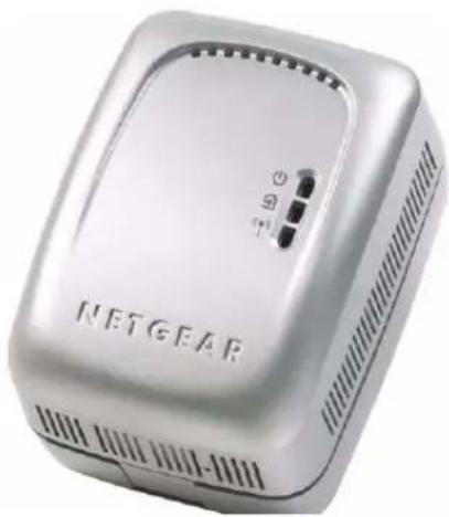
The WGX102 Wireless Unit
The front panel of the WGX102 contains the status lights described below.
natural_image
Exterior view of a silver NETGEAR device with ventilation slots and indicator lights (no readable text or symbols beyond branding)Figure 2-1: WGX102 Front Panel
Table 2-1. Status Light Descriptions
| Label Activity Description | ||
Power On Green | SolidBlinkOff | Power is supplied to the WGB102.Power on self test.Power is not supplied to the WGB102. |
HomePlug — AP Mode Internet — Router Mode | OnOff | The HomePlug port (or Internet port in Router Mode) has detected a link with an attached device.No devices are attached on the Powerline network. |
Wireless On | BlinkOff | The Wireless port is initialized and the wireless feature is enabled.Data is being transmitted or received by the wireless port.There is a problem with the device. See Chapter 8,“Troubleshooting”. |
2-4 Introduction
The Label on the Rear Panel of the WGX102
The label on the rear panel of the WGB102 contains the items listed below.
- MAC address
- Model number
- Serial number
- Unique device Passcode (PWD)
The WGX102 Bottom Panel
The factory default reset push button is located on the bottom panel of the WGB102, as shown below.

text_image
Reset ButtonFigure 2-2: WGX102 Underside
Use a fine pen point or an unfolded paper clip to push in the reset button. If you press the reset button for less than 15 seconds, the WGB102 does a soft reset, similar to unplugging and then plugging the device in again.
When you press the reset button for 15 seconds or more, the WGB102 resets to the factory defaults, as described in “Restoring the Default WGB102 Configuration and Password” on page 8-7.
The XE102 Wall-Plugged Ethernet Bridge
he front panel of the XE102 contains the status lights described below.

natural_image
Exterior view of a silver NETGEAR device with a small indicator button and ports (no readable text beyond branding)Figure 2-3: XE102 Front Panel
You can use the status lights to verify connections. Viewed from top to bottom, the table below describes the lights on the front panel.
Table 2-1. Status Light Descriptions
| Label Activity Description | ||
Power On Green | SolidBlinkOff | Power is supplied to the XE102.Power on self test.Power is not supplied to the XE102. |
HomePlug | OnOff | The HomePlug port has detected a link with an attached device.No devices are attached on the Powerline network. |
Ethernet On | BlinkOff | The Ethernet port has an Ethernet cable connected to a powered on device such as a switch, router, or computer.Data is being transmitted or received by the wireless port.There is no active Ethernet connection. |
The Label on the Rear Panel of the XE102
The label on the rear panel of the WGB102 contains the items listed below.
- MAC address
- Model number
- Serial number
- Unique device Passcode (PWD)
Chapter 3
Installing the Wireless Range Extender Kit
This chapter describes how to set up the 54 Mbps Wall-Plugged Wireless Range Extender Kit WGBX102 on your local area network (LAN) and connect to the Internet.
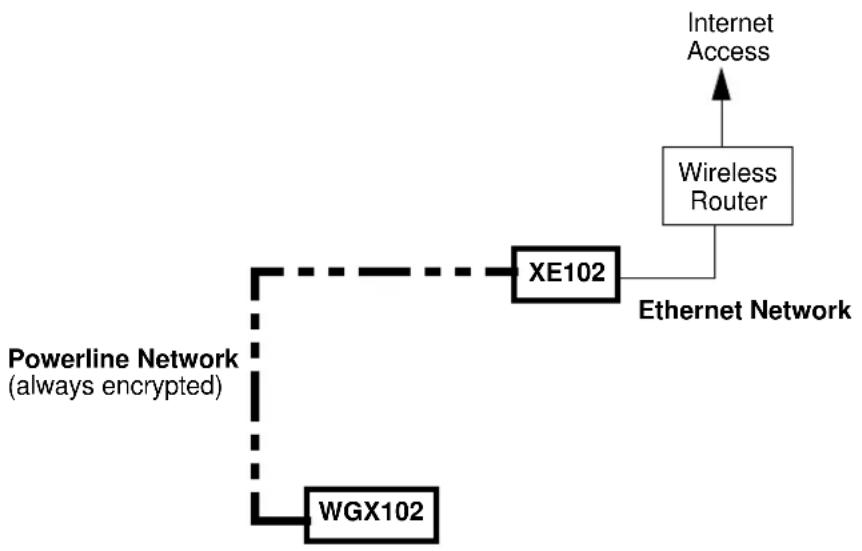
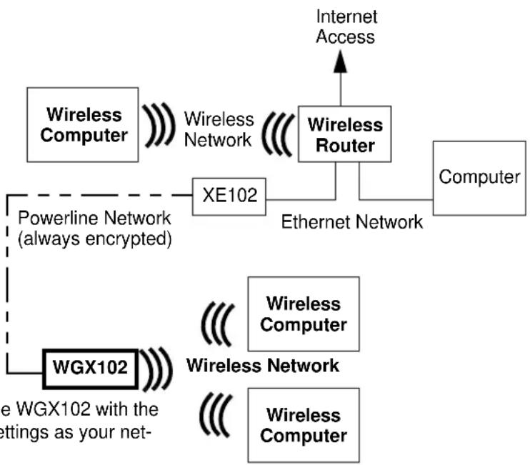
How the Wireless Range Extender Fits in Your Network
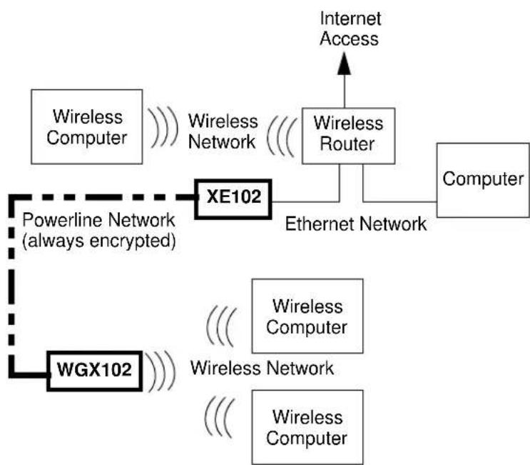
Your existing network probably has Ethernet cabled connections and wireless connections. After you install the Wireless Range Extender Kit, your network will combine these three elements:
- An Ethernet portion where the devices are connected with cables.
- A wireless portion where the devices are connected wirelessly.
- A powerline portion where the devices are connected over your electrical power wires.

flowchart
graph TD
    A["Powerline Network (always encrypted)"] --> B["XE102"]
    B --> C["Wireless Computer"]
    B --> D["Wireless Network"]
    B --> E["Wireless Router"]
    B --> F["Computer"]
    B --> G["Internet Access"]
    B --> H["WGX102"]
    H --> I["Wireless Computer"]
    H --> J["Wireless Network"]
    H --> K["Wireless Computer"]
    style A fill:#f9f,stroke:#333
    style B fill:#ccf,stroke:#333
    style H fill:#cfc,stroke:#333
    style I fill:#fcc,stroke:#333
    style J fill:#fcc,stroke:#333
    style K fill:#fcc,stroke:#333
    style_L["Internet Access"] --> M["Wireless Router"]
    M --> N["Computer"]
    style M --> O["Ethernet Network"]
Figure 3-1: Powerline, Ethernet, and wireless network interconnections
Follow the instructions below to set up your wireless range extender.
Prepare to Install Your Wireless Range Extender
The powerline wireless range extender kit is designed for easy installation. Check that these minimum requirements are met.
- Your Ethernet network is set up with DHCP and an Ethernet port available on your router.
- Your Internet connection is working.
- Your wireless network is set up and you have the Network Name (SSID) and any security settings that you use (such as WEP keys).
- Each computer that will use the Wireless Range Extender Kit must have a wireless card installed and configured. Observe the wireless placement and range guidelines in “Observing Performance, Placement, and Range Guidelines” on page 5-1.
Default Factory Settings
When you first receive your WGB102, the default factory settings are shown below. You can restore these defaults with the factory default reset button on the bottom of the unit.
| FEATURE DEFAULT FACTORY SETTINGS | |
| IP Address | |
| Default type Fixed (static) | |
| Default address 192.168.0.101 | |
| Mode Access Point | |
| Wireless | |
| Wireless Access List (MAC Filtering) All wireless stations allowed | |
| SSID broadcast Enabled | |
| SSID NETGEAR | |
| 802.11b/g RF Channel 11 | |
| Wireless Mode g and b | |
| Authentication Type Automatic | |
| WEP and WPA-PSK Disabled | |
Use the procedures below to customize any of the settings to better meet your networking needs.
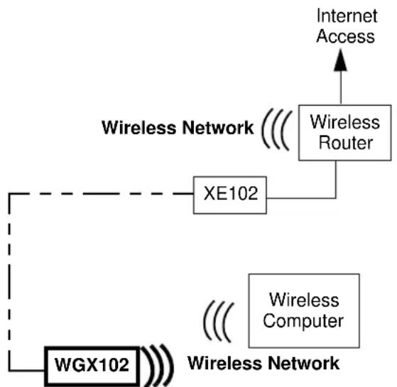
First, Set Up the Powerline Network
flowchart
graph TD
    A["Powerline Network (always encrypted)"] --> B["WGX102"]
    B --> C["XE102"]
    C --> D["Ethernet Network"]
    D --> E["Wireless Router"]
    E --> F["Internet Access"]
Figure 3-2: Powerline, Ethernet, and wireless network interconnections
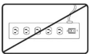
- First, Connect the Wall-Plugged Ethernet Bridge (model XE102)
natural_image
Pure electrical circuit lines without any symbolsWARNING!
Figure 3-3: Powerline caution
Do not connect the WGX102 or the XE102 Wall-Plugged Ethernet Bridge to a power strip, extension cord, or surge protector as this may prevent them from working properly or degrade the network performance.
a. Plug the blue Ethernet cable that came in the box into a LAN port on your router or switch in your network.
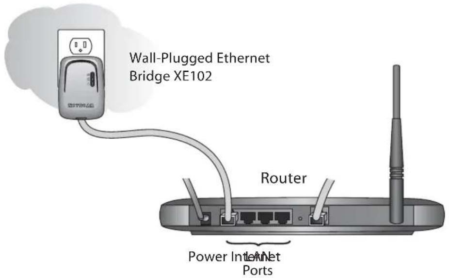
text_image
Wall-Plugged Ethernet Bridge XE102 Router Power Internet PortsFigure 3-4: XE102 connected to a LAN port on your router
b. Plug the XE102 into an electrical outlet near the router.
c. Plug the other end of blue Ethernet cable that came in the box into the XE102.
- Now, Install the Wall Plugged Wireless Range Extender (model WGX102)
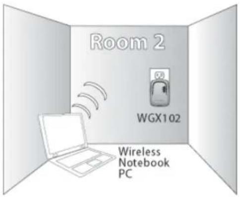
text_image
Room 2 WGX102 Wireless Notebook PCFigure 3-5: WGX102 located near a wireless computer
3-4 Installing the Wireless Range Extender Kit
Plug the WGX102 into an electrical outlet near the wireless computer that you want to connect, and wait one minute. All three LEDs on the WGX102 light up.
- Power: The power light should turn solid green. If it does not, see “Basic Installation Troubleshooting Tips” on page 3-9.
- HomePlug/Internet: The Internet port light should be lit. If not, make sure the Ethernet cable on the XE102 you connected in the previous step is securely attached to the XE102 and the router, that the router is connected to the modem, and the modem is powered on.
- Wireless: The Wireless light should be lit. If the Wireless light is not lit, see “Basic Installation Troubleshooting Tips” on page 3-9.
This completes the powerline installation. You may connect additional XE102 bridges to your network.
Now, Add the WGX102 to Your Wireless Network
flowchart
graph TD
    A["Internet Access"] --> B["Wireless Router"]
    B --> C["XE102"]
    C --> D["WGX102"]
    D --> E["Wireless Computer"]
    style A fill:#f9f,stroke:#333
    style B fill:#ccf,stroke:#333
    style C fill:#cfc,stroke:#333
    style D fill:#fcc,stroke:#333
    style E fill:#cff,stroke:#333
Note: The WGX102 must be configured with the same wireless and IP address settings as your existing network.
Figure 3-6: Powerline and wireless network interconnections
There are two scenarios for adding the WGX102 to your wireless network:
- Plug and play installation: This option works when the wireless settings of your existing network are the same as the default WGX102.
- Custom installation: Use this option when the wireless settings or IP address settings of your existing network are different from the default WGX102. Refer to “Default Factory Settings” on page 3-2.
These procedures for using these two options are presented below.
Plug and Play Installation
If your network uses a NETGEAR wireless router with its default Wireless Network Name (NETGEAR) and you do not use security settings, then the WGX102 works immediately, and the installation is complete. If this is not the case, go to the following section, Custom WGX102 Setup.
You can connect additional XE102 bridges to your network. If you want to change the default powerline passwords for increased security on your powerline network, see “Configuring the Powerline Network Password” on page 4-2. For information about setting up wireless security see “Understanding Basic Wireless Settings” on page 5-2, and the documentation for your wireless router.
Custom WGX102 Setup
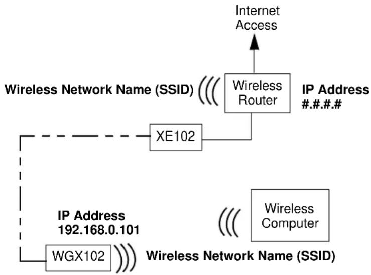
flowchart
graph TD
    A["Internet Access"] --> B["Wireless Router"]
    B --> C["XE102"]
    C --> D["IP Address #..#.#"]
    D --> E["Wireless Computer"]
    E --> F["Wireless Network Name (SSID)"]
    F --> G["WGX102"]
    G --> H["IP Address 192.168.0.101"]
Note: The WGX102 must be configured with the same wireless and IP address settings as your existing network.
Figure 3-7: Powerline and wireless network interconnections
For you to be able to roam between your existing wireless network and the WGX102 and connect easily to either, be sure the WGX102 Network Name (SSID), the wireless security settings, and IP Address subnet (the first three #.#.#. of the addresses in the illustration) must match exactly those settings in your existing wireless network. Follow these instructions to connect to the WGX102 and customize its settings.
- Prepare a wireless computer that has working connection to your existing wireless network. Record the TCP/IP settings of this computer, and the wireless settings -- Wireless Network Name (SSID), and any wireless security settings such as the WEP key.
Alternatively, you can use the WGX102 Configuration Utility to connect via a wireless computer according to the instructions in “Using the WGX102 Configuration Utility” on page 3-12.
- Now, take this computer to the location where the WGX102 is installed.
a. Reconfigure this computer with
- NETGEAR as the Wireless Network Name (SSID)
– A static IP address of 192.168.0.210 and 255.255.255.0 as the Subnet Mask
b. Restart this computer so that these settings take effect.
- Connect to the WGB102 by opening your browser and entering http://192.168.0.101 in the address field.

text_image
Address http://192.168.0.101Figure 3-8: WGX102 Login IP Address
- When prompted, enter admin for the user name and password for the password, both in lower case letters.
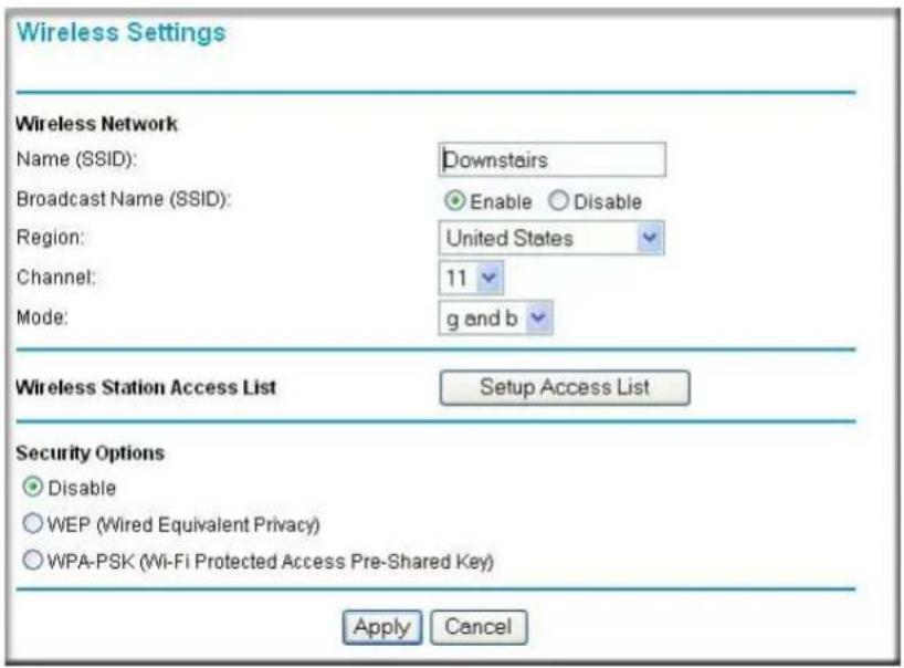
- Click Wireless Settings in the Setup section of the WGX102 main menu. You will then see the Wireless Settings menu.
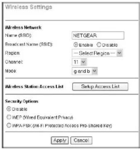
text_image
Wireless Settings Wireless Network Name (SSID): NETGEAR Broadcast Name (SSID): Enable Disable Region: — Select Region — Channel: 11 Mode: g and b Wireless Station Access List Setup Access List Security Options Disable WEP (Wired Equivalent Privacy) WPA-PSK (Wi-Fi Protected Access Pro-Shared Key) Apply CancelFigure 3-9: WGX102 Wireless Settings
- Enter the Network Name (SSID) and wireless security settings for your wireless network.
Be sure to click Apply to save your changes.
Since you are connected to the WGX102 wirelessly, you will be disconnected after applying changes to the WGX102 wireless network name or security settings.
- Assure that the IP address settings match those of your existing router.
3-8 Installing the Wireless Range Extender Kit
From the main menu of the browser interface, under Advanced, click LAN IP Setup to view the LAN IP Setup menu, shown below.

text_image
LAN IP Setup DHCP Client (Obtain IP address automatically) Fixed IP IP Address 192 . 168 . 0 . 101 IP Subnet Mask 255 . 255 . 255 . 0 Apply CancelFigure 3-10: LAN IP Setup menu
If necessary, change the first three positions of the IP Address to match the first three positions of the IP address in your router. You can find your router's address by looking in the Network Properties Status page of any Windows computer connected to your router. The "Gateway" address listed on this Status page is the address of your router.

Note: If you change the IP Address settings of the WGX102, you will be disconnected when you click Apply. Reconfigure your wireless adapter to match the new settings or access the wireless range extender from a wired computer to make any further changes.
- Now reconfigure the computer you used in step 1 back to its original TCP/IP settings. Usually, this will mean setting the computer to get its settings automatically via DHCP. Also, make sure the wireless settings of this computer match the wireless settings of your network.
Test Your Wireless Connectivity
Verify wireless connectivity. Connect to the Internet or log in to the wireless range extender from a computer with a wireless adapter. For wireless connectivity problems, see “Basic Installation Troubleshooting Tips” on page 3-9.
You are now wirelessly connected to the Internet! Implement wireless security according to the instructions in “Implementing Appropriate Wireless Security” on page 5-2.
Basic Installation Troubleshooting Tips
Here are some tips for correcting simple problems you may have.
Be sure to restart your network in this sequence:
- Turn off the modem, router, wireless range extender, and computers
- Turn on the modem, wait two minutes
- Turn on the router and wait one minute
- Plug in the wireless range extender and wait one minute
- Turn on the computers.
Make sure the Ethernet cable is securely plugged into the XE102.
The Internet status light on the wireless range extender will be lit if the Ethernet cable from the XE102 to your router is plugged in securely and the modem and router are turned on.
Make sure the wireless settings in the computer and router match exactly.
The Wireless Network Name (SSID) and WEP or WPA settings of the router and wireless computer must match exactly.
Make sure the network settings of the computer are correct.
LAN and wirelessly connected computers must be configured to obtain an IP address automatically via DHCP. Please see Appendix C, “Preparing Your Network” or the animated tutorials on the CD for help with this.
Check the status lights to verify correct wireless range extender operation.
If the Power light does not turn solid green within two minutes after turning the wireless range extender on, reset the wireless range extender according to the instructions in “Restoring the Default WGX102 Configuration and Password” on page 8-7.
Logging On to Configure the WGX102
-
Connect to the wireless range extender by typing http://192.168.0.101 in the address field of your browser, then click Enter.
-
For security reasons, the wireless range extender has its own user name and password. When prompted, enter admin for the user name and password for the password, both in lower case letters. To change the password, see “Changing the Administrator Password” on page 6-1.
Note: The wireless range extender user name and password are not the same as any user name or password you may use to log in to your Internet connection.

text_image
Connect to 192.168.0.101 WGX102 User name: admin Password: I Remember my password OK CancelFigure 3-11: Login window
- Once you have entered your user name and password, your Web browser should find the Wireless Range Extender Kit and display the page shown below.
flowchart
graph TD
    A["Internet"] --> B["Cable/DSL Modem"]
    B --> C["NetGear Router"]
    C --> D["XE102"]
    D --> E["XE102"]
    E --> F["Through Electrical Outlets"]
    F --> G["WGX 102 AP Mode"]
    G --> H["Laptop"]
    G --> I["Computer"]
    style A fill:#f9f,stroke:#333
    style B fill:#ccf,stroke:#333
    style C fill:#cfc,stroke:#333
    style D fill:#fcc,stroke:#333
    style E fill:#cff,stroke:#333
    style F fill:#ffc,stroke:#333
    style G fill:#cfc,stroke:#333
    style H fill:#fcc,stroke:#333
    style I fill:#cfc,stroke:#333
Figure 3-12: Login result
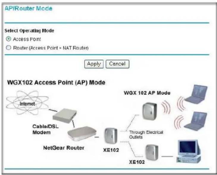
The Wireless Range Extender Kit is in Access Point Mode by default.
- If you do not click Logout, the wireless range extender will wait five minutes after there is no activity before it automatically logs you out.
Using the WGX102 Configuration Utility
You can use the WGX102 Configuration Utility to wirelessly connect to the WGX102 and configure it.
Note: This utility only works with wireless computers.
- Follow the instructions above to set up the XE102 and the WGX102.
- Insert the NETGEAR CD into the computer you will use to set up your 54 Mbps Wall-Plugged Wireless Range Extender Kit WGBX102.

text_image
NETGEAR WGXB102 Resource CD NETGEAR® Everybody's connecting® Smart Wizard™ WGXB102 WGXB102 54 Mbps Wall-Plugged Wireless Range Extender Kit WSX102 Utility Setup Documentation Online Register Online Support Bonus Items ExitFigure 3-13: CD main menu
-
Click WGX102 Utility Setup to begin the configuration utility software installation. Follow the prompts to complete the installation.
-
Go to the Windows Start menu, programs and locate the NETGEAR WGX102 Configuration Utility program group. Run the WGX102 Configuration Utility.

text_image
WGX102 Configuration Utility Welcome to the NETGEAR WGX102 Wireless Range Extender Utility. Use this utility to wirelessly connect to the WGX102 and configure it for your network. The wireless setting of your computer must be set to NETGEAR for Wireless Network Name(SSID), and it must not have any wireless security enable. Note: This Utility only works on PCs that have a working wireless adapter. Next WGX102 Configuration Utility Network Adapter Selection Which wireless network adapter on the PC will you use to connect to the WGX102 ? Click the wireless network adapter on the list to select it. Broadcom 440x 10/100 Integrated Controller NETGEAR WAG511 802.11a/b/g Dual Band Wireless PC Card Selected Network Adapter: NETGEAR WAG511 802.11a/b/g Dual Band Wireless PC Card Click Next to proceed. Back Next WGX102 Configuration Utility WGX102 Device Selection Click to select the WGX102 you will configure. You will be prompted for a user name and password. The default WGX102 user name is admin and the default password is password. Available WGX102 Devices: WGX102 Wireless Extender TAIC3C Back NextFigure 3-14: Login window
Make sure to follow the instructions on the screen regarding the settings of your wireless adapter, and click Next to proceed.
-
Click to highlight the wireless network adapter found in your computer. Then, click Next to proceed. The utility will search for the WGX102. If it does not find the WGX102, make sure your wireless adapter is set according to the instructions on the first screen.
-
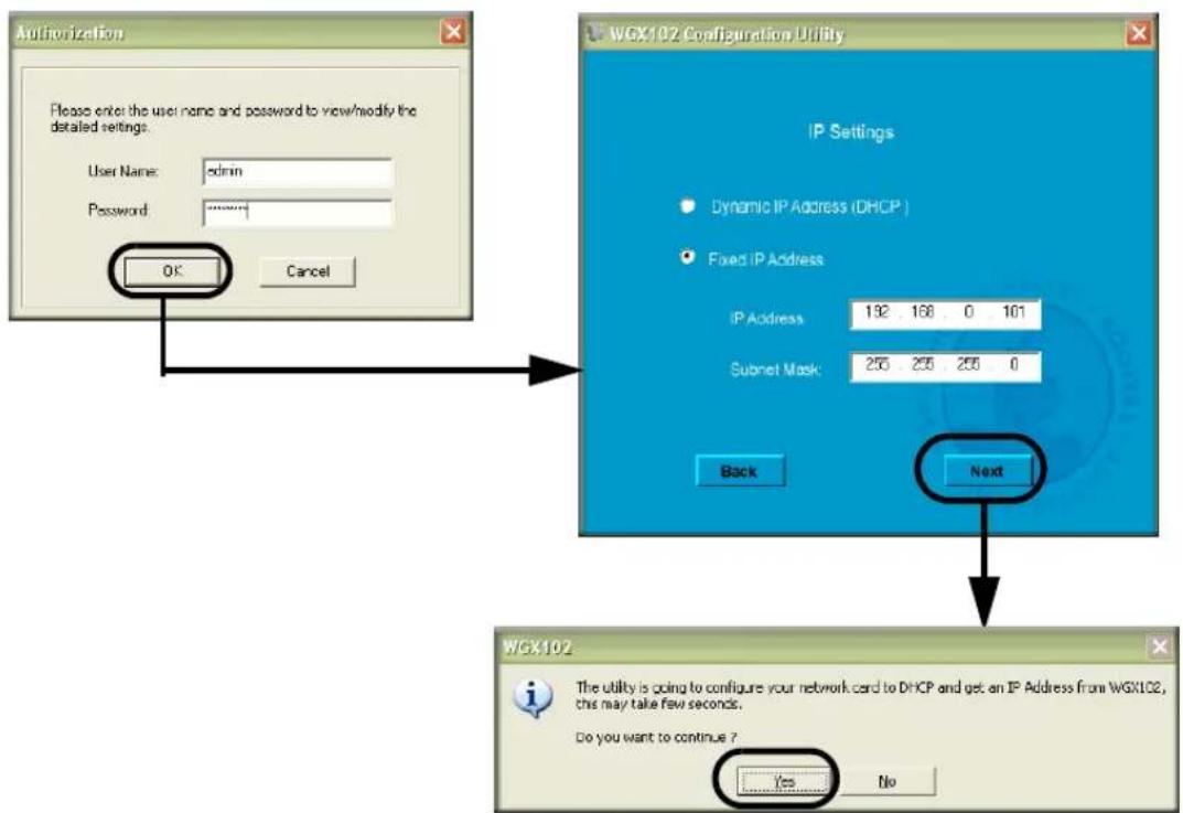
Click Next to proceed. When prompted, enter admin as the user name, and password as the password, both in all lower case letters. Click Ok.
text_image
Authorization Please enter the user name and password to view/modify the detailed settings. User Name: admin Password: ******** OK Cancel WGX102 Configuration Utility IP Settings Dynamic IP Address (DHCP) Fixed IP Address IP Address: 192 168 0 101 Subnet Mask: 255 255 255 0 Back Next WGX102 The utility is going to configure your network card to DHCP and get an IP Address from WGX102, this may take few seconds. Do you want to continue ? Yes NoFigure 3-15: Login window
-
If needed, update the IP Address so that it is in the same subnet as your existing network. For example, if your existing network uses 192.168.1.1 as the address for your router, your would update the IP Address of the WGX102 to be 192.168.1.101. It is best to continue to use a Fixed IP Address for your WGX102 so that it is easy to log in to make configuration changes. If you ever have a problem, you can always use the reset button on the bottom of the WGX102 to restore it to the factory default IP address, password, and wireless settings.
-
Click Next to proceed. You will be informed that the changes you have requested will be made on the WGX102, and the WGX102 Configuration Utility will automatically reconnect your computer using the new settings. Click Ok to proceed with the update. You will get a confirmation message that the change is complete.
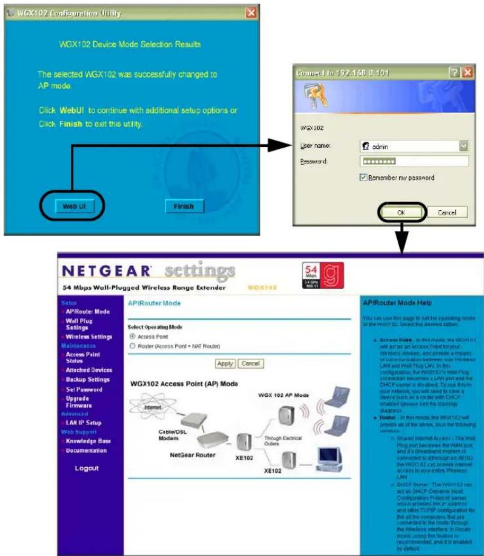
9. Click Web UI to log in to the WGX102.
text_image
WGX102 Configuration Utility WGX102 Device Mode Selection Results The selected WGX102 was successfully changed to AP mode. Click WebUI to continue with additional setup options or Click Finish to exit this utility. Web UI Finish Connect to 192.146.0.101 WGX102 User name: cdmn Password: ******** Remember my password OK Cancel NETGEAR® settings 54 Mbps Wall-Plugged Wireless Range Extender WOX192 54 Mbps WAX192 APIRouter Mode Select Operating Mode Access Point Router (Access Point • NAT Router) Apply Cancel WGX102 Access Point (AP) Mode Internet Cable/DSL Modem NetGear Router XE102 Through Electrical Outlets XE102 APIRouter Mode Help You can use this page to help the operating mode of the POINT 82. Select the desired option: Access Point: In this mode, the WXG102 will act as an Access Point for your Windows devices, and provide a network of userialization between your Windows LAN and Web Plug LAN. In this configuration, the WXG102's WEXI Plug connection becomes a LAN and is the DHCP server is disabled. To use this in your network, you will need to have a device such as a router with DHCP enabled (please set the beginning diagram). Router - In this mode, the WXG102 will provide all of the phone, plus the following seconds: Shared Internet Accounts - The Web Plug port becomes the WAXY port, and if a Broadband modem is continued to through an XE102, the WXG102 can provide internet access to your entire Wireless LAN. DHCP server - The WXG102 can act an DHCP Dynamic Host. Configuration Protocol server, which provides the IP address and other TOPSP configuration for the all the computers that are connected to the module through the Wireless Interface. In Router mode, using this loadset is requirements, and it is enabled by default.Figure 3-16: Login window
When prompted, enter admin as the user name, and password as the password, both in all lower case letters. Click Ok to proceed. The main settings page of the WGX102 will display.
Use the Wireless Settings link in the Setup section of this page to update the WGX102 wireless settings so that they match your wireless network. For assistance with this task, refer to “Setting Up and Testing Basic Wireless Connectivity” on page 5-7. If you do not click Logout, the wireless range extender will wait five minutes after there is no activity before it automatically logs you out.
Configuring the LAN IP Setup Options in Access Point Mode
LAN IP Setup is under the Advanced heading on both the Access Point Mode and Router Mode menus. If you are using the WGB102 in Router Mode, see “Router Mode LAN IP Setup Options” on page 7-24 for configuration information.
From the main menu of the browser interface, under Advanced, click LAN IP Setup to view the LAN IP Setup menu, shown below.

text_image
LAN IP Setup DHCP Client (Obtain IP address automatically) Fixed IP IP Address 192 . 168 . 0 . 101 IP Subnet Mask 255 . 255 . 255 . 0 Apply CancelFigure 3-17: LAN IP Setup menu
DHCP
If selected, the WGB102 will obtain its IP address automatically from a DHCP (Dynamic Host Configuration Protocol) server. Select this option only if your LAN has a DHCP server.
Fixed IP
Select this option if your LAN does not have a DHCP server or if you want the Access Point to use a fixed IP address. The WGB102 default LAN IP configuration is:
- IP addresses — 192.168.0.101. The LAN IP address must be an unused IP address from the IP address range used on your LAN If your LAN has a DHCP server, this IP address should be outside the range of addresses allocated by the DHCP server.
- IP Subnet mask — 255.255.255.0. Combined with the IP address, the IP Subnet Mask allows a device to know which other addresses are local to it, and which must be reached through a gateway or router. The Subnet Mask specifies the network number portion of the IP address. It must match the settings of the other PCs and devices on your LAN.
Chapter 4
Powerline Network Configuration and Security
This chapter describes how to use the powerline configuration and security features of your 54 Mbps Wall-Plugged Wireless Range Extender Kit WGBX102.
Understanding How the Powerline Network Password Works
flowchart
graph TD
    A["Computer"] --> B["Wireless Router"]
    B --> C["Wireless Router"]
    C --> D["Wireless Computer"]
    D --> E["Wireless Computer"]
    E --> F["Wireless Computer"]
    F --> G["Wireless Computer"]
    G --> H["XE102"]
    H --> I["Powerline Network (always encrypted)"]
    H --> J["WGX102"]
    H --> K["Internet Access"]
    style H stroke:#000,stroke-width:2px
Figure 4-1: Powerline, Ethernet, and wireless network interconnections
The HomePlug devices in your 54 Mbps Wall-Plugged Wireless Range Extender Kit WGBX102 include security encryption features that are always enabled. The HomePlug powerline network always encrypts the data sent over the electrical power wires. However, you can change the default password. You should do so, especially if you live in a multi-family dwelling unit. Some important features of this security are listed here.
- Because the data is always encrypted, the password allows you to protect your network from unauthorized access via the powerline network.
• The password is case sensitive. -
The password defines a network. That is, if there are four powerline devices in use in a home and two have the password upstairs, and two have the password downstairs, the “upstairs” powerline devices will communicate with one another but will not communicate with the “downstairs” devices and the “downstairs” devices will communicate with one another but not with the “upstairs” devices.
-
In order for powerline devices to communicate on the same network, every device in the powerline network must have the same password.
– Powerline devices on different networks will not be able to communicate.
Note: Once you begin to change the password for each device, portions of your network may become disabled until all of the devices have been set with the new password.
Configuring the Powerline Network Password
You can change either a single or all powerline devices on the network at the same time. You assign a Network Password using the WGX102 Wall Plug Settings screen.
- From the main menu of the browser interface, under the Setup section, click Wall Plug Settings to display the Wall Plug Settings screen.

text_image
Wall Plug Settings Network Password HomePlug Network Password: HomePlug Other HomePlug Stations You can assign the Network Password above to all the HomePlug stations listed below.Name Passcode(PWD) Status
○ 1 XE102_home VJ5R-SQVX-LBXB-K4S9 OK Add Delete Assign PasswordFigure 4-2: Wall Plug Settings screen
4-2 Powerline Network Configuration and Security
- Enter the desired HomePlug Network Password in the field provided.
You can also assign this password to other HomePlug stations on your powerline network. Click the Add button to add a HomePlug Station to the list.

text_image
Add HomePlug Station Name: Passcode: Add CancelFigure 4-3: Add HomePlug Station screen
To assign the Network Password to other HomePlug Stations:
a. Enter a suitable name for the device. For example, a location identifier can be useful such as Downstairs, Upstairs, or Garage. This name is only used for your reference.
b. Each HomePlug station has a unique device Passcode (PWD) in the format xxxx-xxxx-xxxx-xxxx, usually shown on a label on the base or rear. Check each HomePlug device to find the Passcode to enter.
For each NETGEAR Powerline device that you are installing on your network, write this number down.
Example:
Device Location: Upstairs Bedroom PWD: MX96-DHEE-U9Y3-BXJB

text_image
NETGEAR® Powerline Adapter XE102 Power Powerline Ethernet AC 100-120V, 110mA, 50-60Hz LISTED I.T.E. E212778 Tested To Comply With FCC Standards FOR HOME OR OFFICE USE INDOOR USE ONLY MAC SERIAL PWD MX96-DHEE-U9Y3-BXJE Made in Chinac. Click Add.
- On the Wall Plug Settings screen, click Assign Password. The Network Password is then assigned to all the HomePlug stations listed in the table, provided they are currently connected with a powerline connection.
Chapter 5
Wireless Configuration and Security
This chapter describes how to configure the wireless features of your Wireless Range Extender Kit. In planning your wireless network, you should consider the level of security required. You should also select the physical placement of your wireless range extender in order to maximize the network speed. For further information on wireless networking, refer to Appendix C, “Wireless Networking Basics”.
Observing Performance, Placement, and Range Guidelines
The operating distance or range of your wireless connection can vary significantly based on the physical placement of the wireless range extender. The latency, data throughput performance, and notebook power consumption of wireless adapters also vary depending on your configuration choices.

Note: Failure to follow these guidelines can result in significant performance degradation or inability to wirelessly connect to the wireless range extender. For complete range/performance specifications, please see Appendix A, “Technical Specifications”.
For best results, place your wireless range extender:
- Near the center of the area in which your computers will operate.
- Away from sources of interference, such as computers, microwaves, and 2.4 GHz cordless phones.
- Away from large metal surfaces.
The time it takes to establish a wireless connection can vary depending on both your security settings and placement. Connections using WEP or WPA can take slightly longer to establish. Also, WEP and WPA encryption can consume more battery power on a notebook computer.
Implementing Appropriate Wireless Security

Note: Indoors, computers can connect over 802.11b/g wireless networks at ranges of up to 300 feet. Such distances can allow for others outside of your immediate area to access your network.
Unlike wired network data, your wireless data transmissions can be received well beyond your walls by anyone with a compatible adapter. For this reason, use the security features of your wireless equipment. The Wireless Range Extender Kit provides highly effective security features that are covered in detail in this chapter. Deploy the security features appropriate to your needs.
Wireless Data Security Options
There are several ways you can enhance the security of your wireless network.
- Restrict Access Based on MAC address. You can restrict access to only trusted computers so that unknown computers cannot wirelessly connect to the WGB102. MAC address filtering adds an obstacle against unwanted access to your network, but the data broadcast over the wireless link is fully exposed.
- Turn Off the Broadcast of the Wireless Network Name SSID. If you disable broadcast of the SSID, only devices that have the correct SSID can connect. This nullifies the wireless network “discovery” feature of some products such as Windows XP, but the data is still fully exposed to a determined snoop using specialized test equipment like wireless sniffers.
- WEP. Wired Equivalent Privacy (WEP) data encryption provides data security. WEP Shared Key authentication and WEP data encryption will block all but the most determined eavesdropper.
- WPA-PSK. Wi-Fi Protected Access (WPA) data encryption provides strong data security. WPA-PSK will block eavesdropping. Because this is a new standard, wireless device driver and software availability may be limited.
Understanding Basic Wireless Settings
To configure the Wireless settings of your wireless range extender, click the Wireless link in the main menu of the browser interface. The Wireless Settings menu appears, as shown below.

text_image
Wireless Settings Wireless Network Name (SSID): Downstairs Broadcast Name (SSID): Enable Disable Region: United States Channel: 11 Mode: g and b Wireless Station Access List Setup Access List Security Options Disable WEP (Wired Equivalent Privacy) WPA-PSK (Wi-Fi Protected Access Pre-Shared Key) Apply CancelFigure 5-1: Wireless Settings menu
- Name (SSID). The SSID is also known as the wireless network name. Enter a value of up to 32 alphanumeric characters. In a setting where there is more than one wireless network, different wireless network names provide a means for separating the traffic. Any device you want to participate in a particular wireless network will need to use this SSID for that network. The WGB102 default SSID is: NETGEAR.
- Broadcast of Name (SSID). If you disable broadcast of the SSID, only devices that have the correct SSID can connect. Disabling SSID broadcast nullifies the wireless network ‘discovery’ feature of some products such as Windows XP.
- Region. This field identifies the region where the WGXB102 can be used. It may not be legal to operate the wireless features of the wireless range extender in a region other than one of those identified in this field.
-
Channel. This field determines which operating frequency will be used. It should not be necessary to change the wireless channel unless you notice interference problems with another nearby access point. For more information on the wireless channel frequencies please refer to "Wireless Channels" on page C-7.
-
Mode. This field determines which data communications protocol will be used. You can select “g only,” “b only,” or “g and b.” “g only” dedicates the WGB102 to communicating with the higher bandwidth 802.11g wireless devices exclusively. “b only” dedicates the WGB102 to communicating with the higher bandwidth 802.11b wireless devices exclusively. The “g and b” mode provides backward compatibility with the slower 802.11b wireless devices while still enabling 802.11g communications.
- Wireless Card Access List. When the Trusted PCs Only radio button is selected, the WGB102 checks the MAC address of the wireless station and only allows connections to computers identified on the trusted computers list.
- Security Options. These options are the wireless security features you can enable. The table below identifies the various basic wireless security options. A full explanation of these standards is available in Appendix C, “Wireless Networking Basics”.
Table 5-1. Basic Wireless Security Options
| Field Description | |
| Disable | No wireless security. |
| WEP WEP offers the following options:Open SystemWith Open Network Authentication and 64- or 128-bit WEP Data Encryption, the WGXB102 does perform 64- or 128-bit data encryption but does not perform any authentication.Shared KeyShared Key authentication encrypts the SSID and data.Choose the Encryption Strength (64- or 128-bit data encryption). Manually enter the key values or enter a word or group of printable characters in the Passphrase box. Manually entered keys are case sensitive but passphrase characters are not case sensitive.Note: Not all wireless adapter configuration utilities support passphrase key generation.A u toAutomatically determines whether Open System or Shared Key should be used. | |
| WPA-PSK | WPA-Pre-shared Key does perform authentication, uses 128-bit data encryption and dynamically changes the encryption keys making it nearly impossible to circumvent.Enter a word or group of printable characters in the Passphrase box. These characters are case sensitive.Note: Not all wireless adapter configuration utilities support WPA. Furthermore, client software is required on the client. Windows XP and Windows 2000 with Service Pack 3 do include the client software that supports WPA. Nevertheless, the wireless adapter hardware and driver must also support WPA. |
Information to Gather Before Changing Basic Wireless Settings
Before customizing your wireless settings, print this form and record the following information. If you are working with an existing wireless network, the person who set up or is responsible for the network will be able to provide this information. Otherwise, you will choose the settings for your wireless network. Either way, record the settings for your wireless network in the spaces below.
- Wireless Network Name (SSID): ____ The SSID, identifies the wireless network. You can use up to 32 alphanumeric characters. The SSID is case sensitive. The SSID in the wireless adapter card must match the SSID of the wireless range extender. In some configuration utilities (such as in Windows XP), the term “wireless network name” is used instead of SSID.
• If WEP Authentication is Used. Circle one: Open System, Shared Key, or Auto.
Note: If you select Shared Key, the other devices in the network will not connect unless they are set to Shared Key as well and are configured with the correct key.
- WEP Encryption key size. Choose one: 64-bit or 128-bit. Again, the encryption key size must be the same for the wireless adapters and the wireless range extender.
-
Data Encryption (WEP) Keys. There are two methods for creating WEP data encryption keys. Whichever method you use, record the key values in the spaces below.
-
Passphrase method. ____ These characters are case sensitive. Enter a word or group of printable characters and click the Generate Keys button. Not all wireless devices support the passphrase method.
- Manual method. These values are not case sensitive. For 64-bit WEP, enter 10 hex digits (any combination of 0-9 or a-f). For 128-bit WEP, enter 26 hex digits.
Key 1: ____
Key 2: ____
Key 3: ____
Key 4: ____
- If WPA-PSK Authentication is Used.
- Passphrase: ____ These characters are case sensitive. Enter a word or group of printable characters. When you use WPA-PSK, the other devices in the network will not connect unless they are set to WPA-PSK as well and are configured with the correct Passphrase.
Use the procedures described in the following sections to configure the WGB102. Store this information in a safe place.
Default Factory Settings
When you first receive your WGB102, the default factory settings are shown below. You can restore these defaults with the factory default reset button on the bottom of the unit.
| FEATURE DEFAULT FACTORY SETTINGS | |
| Wireless Access List (MAC Filtering) All wireless stations allowed | |
| SSID broadcast Enabled | |
| SSID NETGEAR | |
| 802.11b/g RF Channel 11 | |
| Mode g and b | |
| Authentication Type Automatic | |
| WEP and WPA-PSK Disabled | |
After you install the Wireless Range Extender Kit, use the procedures below to customize any of the settings to better meet your networking needs.
Setting Up and Testing Basic Wireless Connectivity
flowchart
graph TD
    A["Wireless Computer"] -->|Wireless Network| B["XE102"]
    B -->|Ethernet Network| C["Computer"]
    D["WGX102"] -->|Powerline Network (always encrypted)| B
    E["Wireless Computer"] --> F["Wireless Network"]
    G["Wireless Computer"] --> H["Wireless Network"]
    I["Internet Access"] --> J["Wireless Router"]
    J --> B
    style A fill:#f9f,stroke:#333
    style D fill:#f9f,stroke:#333
    style E fill:#f9f,stroke:#333
    style G fill:#f9f,stroke:#333
    style I fill:#f9f,stroke:#333
Tip: Configure the WGX102 with the same wireless settings as your network.
Figure 5-2: Powerline, Ethernet, and wireless network interconnections
The wireless feature of your 54 Mbps Wall-Plugged Wireless Range Extender Kit WGBX102 includes security features you can set to match the settings of your existing wireless network.
Follow the instructions below to set up and test the wireless settings of your WGX102.
-
Log in to the Wireless Range Extender Kit at its default LAN address of http://192.168.0.101 with its default user name of admin and default password of password, or using whatever LAN address and password you have set up.
-
Click Wireless Settings in the main menu of the Wireless Range Extender Kit.
text_image
Wireless Settings Wireless Network Name (SSID): Downstairs Broadcast Name (SSID): Enable Disable Region: United States Channel: 11 Mode: g and b Wireless Station Access List Setup Access List Security Options Disable WEP (Wired Equivalent Privacy) WPA-PSK (Wi-Fi Protected Access Pre-Shared Key) Apply CancelFigure 5-3: Wireless Settings menu
- Enter the wireless network name (SSID) of your existing network.
Note: The SSID is case sensitive; NETGEAR is not the same as nETgear. Also, the SSID of any wireless adapters must match the SSID you configure in the WGX102. If they do not match, you will not get a wireless connection to the WGX102.
-
Select Enable to broadcast the SSID.
-
Set the Region. Select the region in which the wireless interface will operate.
-
Set the Channel. The default channel is 11. It is best if this is separated by 5 positions from the channel already being used in your existing wireless network. For example, if your existing wireless network uses channel 11, then set the WGX102 to channel 6.
For more information on the wireless channel frequencies please refer to "Wireless Channels" on page C-7.
-
For initial configuration and test, leave the Wireless Card Access List set to "Everyone."
-
Set the Security Options to match your existing wireless network settings.
5-8 Wireless Configuration and Security

Note: If you use a wireless computer to configure wireless settings, you will be disconnected when you click Apply. Reconfigure your wireless adapter to match the new settings or access the wireless range extender from a wired computer to make any further changes.
- Click Apply to save your changes.
- Configure and test your computers for wireless connectivity.
Verify that the wireless adapters of your computers have the same SSID and security options that you configured in the WGX102. Check that they have a wireless link and are able to obtain an IP address by DHCP from the wireless range extender.
Once your computers have basic wireless connectivity to the WGX102, you can configure the advanced wireless security functions of the wireless range extender.
WEP Security Options
To configure WEP data encryption, follow these steps:

Note: If you use a wireless computer to configure WEP settings, you will be disconnected when you click Apply. You must then either configure your wireless adapter to match the wireless range extender WEP settings or access the wireless range extender from a wired computer to make any further changes.
- Click Wireless Settings in the main menu of the WGX102.
- From the Security Options menu, select WEP. The WEP options display.

text_image
Security Options Disable WEP (Wired Equivalent Privacy) WPA-PSK (Wi-Fi Protected Access Pre-Shared Key) Security Encryption (WEP) Authentication Type: Open System Encryption Strength: 128bit Security Encryption (WEP) Key Passphrase: Generate Key 1: 0cf6e5413e1f454d59231db6bd Key 2: 0cf6e5413e1f454d59231db6bd Key 3: 0cf6e5413e1f454d59231db6bd Key 4: 0cf6e5413e1f454d59231db6bd Apply CancelFigure 5-4. WEP settings section
- Select the Authentication Type from the drop-down list. Choices are Automatic, Open System, or Shared Key. Automatic is selected by default.
-
Select the Encryption Strength from the drop-down list. Choices are Disable, 64-bit, or 128-bit:
-
64-bit — uses ten hexadecimal digits (any combination of 0-9, a-f, or A-F)
-
128-bit — uses twenty-six hexadecimal digits (any combination of 0-9, a-f, or A-F)
-
You can manually or automatically program the four data encryption keys. These values must be identical on all computers and Access Points in your network.
-
Automatic — enter a word or group of printable characters in the Passphrase box and click the Generate button. The passphrase is case sensitive; NETGEAR is not the same as nETgear. The four key boxes are automatically populated with key values.
- Manual — enter ten hexadecimal digits (any combination of 0-9, a-f, or A-F). These entries are not case sensitive; AA is the same as aa. Select which of the four keys will be active.
Please refer to “Authentication and WEP” on page C-3 for a full explanation of each of these options, as defined by the IEEE 802.11 wireless communication standard.
- Click Apply to save your settings.
WPA-PSK Wireless Security Options
Note: Not all wireless adapters support WPA. Furthermore, client software is also required. Windows XP and Windows 2000 with Service Pack 3 do include WPA support. Nevertheless, the wireless adapter hardware and driver must also support WPA. For instructions on configuring wireless computers or PDAs for WPA-PSK security, consult the documentation for the product you are using.
To configure WPA-PSK, follow these steps:
- Click Wireless Settings in the main menu.
- Select WPA-PSK for the Security Type. The WPA-PSK security options display.

text_image
Security Options Disable WEP (Wired Equivalent Privacy) WPA-PSK (Wi-Fi Protected Access Pre-Shared Key) Security Encryption (WPA-PSK) Passphrase: passphrase1 | (8-63 characters) Key Lifetime: 60 (minutes) Apply CancelFigure 5-5: WPA Settings section
- Enter a word or group of 8-63 printable characters in the Passphrase box.
- Enter the Key Lifetime. This setting determines how often the encryption key is changed. Shorter periods provide greater security, but can affect performance. The default is 60 minutes.
- Click Apply to save your settings.
Access List: Restricting Wireless Access by MAC Address

Note: When configuring the WGX102 from a wireless computer whose MAC address is not in the Trusted PC list, if you select Turn Access Control On, you will lose your wireless connection when you click Apply. You must then access the wireless range extender from a wired computer or from a wireless computer that is on the access control list to make any further changes.
To restrict access based on MAC addresses, follow these steps:
- Click Wireless Settings in the main menu of the browser interface.
- In the Wireless Card Access List section, click Setup Access List to display the Wireless Card Access List.
- Click Add to go to Wireless Card Access Setup, where you can add a wireless card to the list.
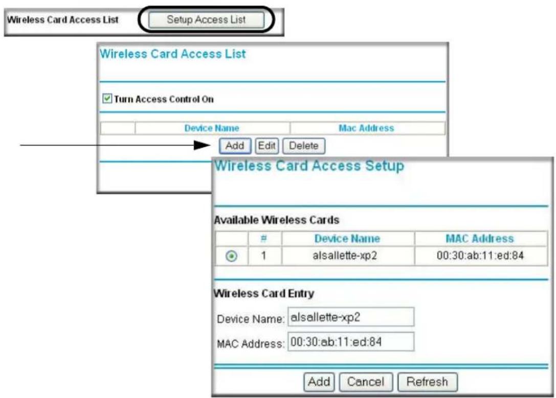
text_image
Wireless Card Access List Setup Access List Wireless Card Access List ✓ Turn Access Control On Device Name Mac Address Add Edit Delete Wireless Card Access Setup Available Wireless CardsDevice Name MAC Address
1 alsallette-xp2 00:30:ab:11:ed:84 Wireless Card Entry Device Name: alsallette-xp2 MAC Address: 00:30:ab:11:ed:84 Add Cancel RefreshFigure 5-6: Wireless Card Access List Setup
5-12 Wireless Configuration and Security
- Then, either select from the list of available wireless cards the WGB102 has found in your area, or enter the MAC address and device name for a device you plan to use. You can usually find the MAC address printed on the wireless adapter.
Note: You can copy and paste the MAC addresses from the Attached Devices menu into the MAC Address box of this menu. To do this, configure each wireless computer to obtain a wireless link to the WGX102. The computer should then appear in the Attached Devices menu.
- Click Add to add this wireless device to the Wireless Card Access List. The screen changes back to the list screen. Repeat these steps for each additional device you wish to add to the list.
- Select the Turn Access Control On check box.
- Be sure to click Apply to save your wireless access control list settings.
Now, only devices on this list will be allowed to wirelessly connect to the WGX102.
Chapter 6
Maintenance
This chapter describes how to use the maintenance features of your 54 Mbps Wall-Plugged Wireless Range Extender Kit WGBX102.
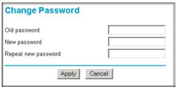
Changing the Administrator Password

Note: Before changing the WGX102 password, use the backup feature to save your configuration settings. If after changing the password, you forget the new password you assigned, you will have to reset the WGX102 back to the factory defaults to be able to log in using the default password of password. This means you will have to restore all the wireless range extender configuration settings. If you ever have to reset the WGX102 back to the factory defaults, you can restore your settings from the backup.
The default password for the WGX102 Web browser interface is password. Change this password to a more secure password.
From the main menu of the browser interface, under the Maintenance heading, select Set Password to bring up the menu shown below.
text_image
Change Password Old password New password Repeat new password Apply CancelFigure 6-1: Set Password menu
To change the password, first enter the old password, then enter the new password twice. Click Apply.
Viewing Access Point Status Information
Note: You must be in Access Point Mode to view the Access Point Status screen. If you are in Router Mode, see “Viewing Router Status Information” on page 6-5 for status information instead.
The Access Point Status menu provides status and usage information. From the Maintenance section of the main menu of the browser interface, select Access Point Status to view the status screen, shown below.

text_image
Access Point Status Device Name WGX102 Firmware Version V1.0_22 LAN MAC Address 00:C0:02:FF:98:5E IP Address 192.168.0.101 DHCP Client No IP Subnet Mask 255.255.255.0 Wireless Name (SSID) Downstairs Region United States Channel 11 Mode g and b Broadcast Name On Show StatisticsFigure 6-2: Access Point Status screen
This screen shows the following parameters:
Table 6-1. Access Point Status fields
| Field | Description |
| Device Name The Host Name assigned to the WGB102. | |
| Firmware Version The wireless range extender's firmware version. | |
| LAN Port These parameters apply to the local powerline port of the WGB102.MAC Address The Media Access Control address used by the LAN port of the WGB102.IP Address The IP address used by the local port of the WGB102. The default is 192.168.0.101IP Subnet Mask The IP Subnet Mask used by the local port of the WGB102. The default is 255.255.255.0DHCP Identifies if the wireless range extender's built-in DHCP server is active for the powerline attached devices. | |
| Wireless Port These parameters apply to the Wireless port of the WGB102.Name (SSID) The wireless network name (SSID) used by the wireless port of the WGB102. The default is NETGEAR.Region The geographic region where the wireless range extender is being used. It may be illegal to use the wireless features of the WGB102 in some parts of the world.Channel Identifies the wireless channel being used. See “Wireless Channels” on page C-7 for the frequencies used on each channel. | |
| Mode | g and b, b only, or g only |
| Broadcast Name | Shows whether the wireless range extender is broadcasting its name. |
Click the Show Statistics button to display access point usage statistics, as shown below.

text_image
NETGEAR Access Point Statistics - Microsoft Internet Explorer System Up Time 00:31:51 Port Status TxPkts RxPkts Collisions Tx B/s Rx B/s Up Time LAN 14M 993 843 0 784 354 00:31:51 WLAN 54M 358 192 0 55 14 00:31:51 Poll Interval: 5 (secs) Set Interval Stop Done InternetFigure 6-3: Access Point Statistics screen
The Access Point Statistics screen fields are described in the table below:
Table 6-3: Access Point Statistics Items
| Item Description | |
| Port The statistics for the LAN (local powerline) and WLAN (wireless) ports. For each port,the screen displays:Status The maximum link speed of the port.TxPkts The number of packets transmitted on this port since reset or manual clear.RxPkts The number of packets received on this port since reset or manual clear.Collisions The number of collisions on this port since reset or manual clear.Tx B/s The current transmission (outbound) bandwidth used on the WLAN and LAN ports.Rx B/s The current reception (inbound) bandwidth used on the WLAN and LAN ports.Up Time The time elapsed since this port acquired the link. | |
| Poll Interval Specifies the intervals at which the statistics are updated in this window. Click Stop tofreeze the display. | |
| Set Interval Enter a time and click the button to set the polling frequency. | |
| Stop | Click the Stop button to freeze the polling information. |
6-4 Maintenance
Viewing Router Status Information
Note: You must be in Router Mode to view the Router Status Mode. If you are in Access Point Mode, see “Viewing Access Point Status Information” on page 6-2 for status information instead.
The Router Status screen provides status and usage information. From the Maintenance section of the main menu of the browser interface, select Router Status to view the status screen, shown below.
| Router Status | |
| Account Name | WGX102 |
| Firmware Version | V1.0_22 |
| Internet | |
| MAC Address | 00:0F:B5:1A:4C:3D |
| IP Address | 192.168.1.2 |
| DHCP | DHCP Client |
| IP Subnet Mask | 255.255.255.0 |
| Domain Name Server | 192.168.1.1 |
| LAN | |
| MAC Address | 00:0F:B5:1A:4C:3C |
| IP Address | 192.168.0.101 |
| DHCP | On |
| IP Subnet Mask | 255.255.255.0 |
| Wireless | |
| Name (SSID) | NETGEAR-PY |
| Region | United States |
| Channel | 4 |
| Mode | g and b |
| Broadcast Name | On |
| Show Statistics | Connection Status |
Figure 6-4: Router Status screen
This screen shows the following parameters:
Table 6-1. Router Status Fields
| Field | Description |
| Account Name The Host Name assigned to the WGB102. | |
| Firmware Version The wireless range extender firmware version. | |
| Internet Port These parameters apply to the Internet (WAN) port of the WGB102.MAC Address The Media Access Control (MAC) address used by the Internet (WAN) port of the WGB102.IP Address The IP address used by the Internet (WAN) port of the WGB102. If no address is shown, the wireless range extender cannot connect to the Internet.DHCP If set to None, the WGB102 is configured to use a fixed IP address on the WAN. If set to a client, such as PPPOE, the WGB102 is configured to obtain an IP address dynamically from the ISP.IP Subnet Mask The IP Subnet Mask used by the Internet (WAN) port of the WGB102.Domain Name Server The Domain Name Servers (DNS) mapping descriptive names of network resources to IP addresses. | |
| LAN Port These parameters apply to the local powerline port of the WGB102.MAC Address The Media Access Control address used by the local port of the WGB102.IP Address The IP address used by the local port of the WGB102. The default is 192.168.0.101DHCP Identifies if the wireless range extender's built-in DHCP server is active for the LAN attached devices.IP Subnet Mask The IP Subnet Mask used by the local port of the WGB102. The default is 255.255.255.0 | |
| Wireless Port These parameters apply to the wireless port of the WGB102.Name (SSID)The wireless network name (SSID) used by the wireless port of the WGB102. The default is NETGEAR.RegionThe geographic region where the WGB102 is being used.ChannelThe channel the wireless port is using. See “Wireless Channels” on page C-7 for the frequencies used on each channel.ModeThe current mode — g and b, g only, or b only.Broadcast NameIndicates whether the WGB102 is broadcasting its SSID. | |
From the Router Status screen, click the Connection Status button to display the connection status, as shown below.

text_image
Connection Status IP Address 192.168.1.2 Subnet Mask 255.255.255.0 Default Gateway 192.168.1.1 DHCP Server 192.168.1.1 DNS Server 192.168.1.1 Lease Obtained 7 days,0 hrs,0 minutes Lease Expires 6 days,23 hrs,44 minutes Release Renew Close Window Done InternetFigure 6-5: Connection Status screen
This screen shows the following fields:.
Table 6-1. Connection Status Fields
| Field Description | |
| IP Address The WAN | (Internet) IP Address assigned to the wireless range extender. |
| Subnet Mask The WAN | (Internet) Subnet Mask assigned to the WGB102. |
| Default Gateway The WAN | (Internet) default gateway the WGB102 communicates with. |
| DHCP Server The WAN | (Internet) DHCP server IP address. |
| DNS Server The WAN | (Internet) DNS server IP addresses on the network. |
| Lease Obtained | The length of time the wireless range extender has been connected to your Internet service provider's network. |
| Lease Expires The length of time before the lease expires. | |
Click the Renew button to renew the DHCP lease. Click the Release button to disconnect from the WAN.
Viewing a List of Attached Devices
The Attached Devices menu contains a table of all IP devices that the wireless range extender has discovered on the local network. From the main menu of the browser interface, under the Maintenance heading, select Attached Devices to view the table, shown below.

text_image
Attached Devices # IP Address Device Name MAC Address 1 192.168.0.4 UNKNOWN NAME 00:09:5B:00:22:04 Refresh Attached HomePlug Devices # MAC Address Data Rate (Mbps) 1 00:09:5B:81:FC:90 -- Scan Powerline NetworkFigure 6-6: Attached Devices menu
For each device attached to the WGB102, the first table shows the IP address, NetBIOS Device Name (if available), and Ethernet MAC address. Note that if the router is rebooted, the table data is lost until the WGB102 rediscovers the devices. To force the wireless range extender to look for attached devices, click the Refresh button.
The second table shows the MAC (Media Access Control) Address and Data Rate for each HomePlug PC or device on the HomePlug network detected by the WGX102. You cannot change any of the values shown here. To update this list and to show the current attached devices, click the Scan Powerline Network button.
Configuration File Management
The configuration settings of the Wireless Range Extender Kit are stored within the wireless range extender in a configuration file. This file can be saved (backed up) to a PC, retrieved (restored) from the PC, or cleared to factory default settings.
From the main menu of the browser interface, under the Maintenance heading, select Backup Settings to bring up the menu shown below.

text_image
Backup Settings Save a Copy of Current Settings Backup Restore Saved Settings from a File Browse... Restore Revert to Factory Default Settings EraseFigure 6-7: Backup Settings menu
Backing Up the Configuration
To save your settings, click the Backup button. Your browser extracts the configuration file from the router and prompts you for a location on your PC to store the file. You can give the file a meaningful name at this time, such as pacbell.cfg.
Restoring the Configuration
To restore your settings from a saved configuration file, enter the full path to the file on your PC or click the Browse button to browse to the file. When you have located it, click the Restore button to send the file to the wireless range extender. The WGB102 then reboots automatically.
Warning: Do not interrupt the reboot process.
Erasing the Configuration
It is sometimes desirable to restore the wireless range extender to the original default settings. The Erase function restores all factory settings. After an erase, the wireless range extender's password is password and the LAN IP address is 192.168.0.101.
To erase the configuration, click and hold the reset button for at least 15 seconds.
Warning: Do not turn off the power to the WGB102 until the power LED has turned solid green.
To restore the factory default configuration settings without knowing the login password or IP address, you must use the default reset button on the bottom panel of the WGB102. See “Restoring the Default WGB102 Configuration and Password” on page 8-7.
Upgrading the Wireless Range Extender Software
| Note: Before upgrading the WGB102 software, use the Backup Settings menu to save your configuration settings. Any wireless range extender upgrade reverts the WGB102 settings back to the factory defaults. After completing the upgrade, you can restore your settings from the backup. |
The software of the Wireless Range Extender Kit is stored in FLASH memory, and can be upgraded as new software is released by NETGEAR. Upgrade files can be downloaded from the NETGEAR Web site. If the upgrade file is compressed (.ZIP file), you must first extract the file before sending it to the wireless range extender. The upgrade file can be sent to the router using your browser.
Note: The Web browser used to upload new firmware into the Wireless Range Extender Kit must support HTTP uploads. NETGEAR recommends using Microsoft Internet Explorer or Netscape Navigator 3.0 or above.
From the main menu of the browser interface, under the Maintenance heading, select Upgrade Firmware to display the menu shown below.
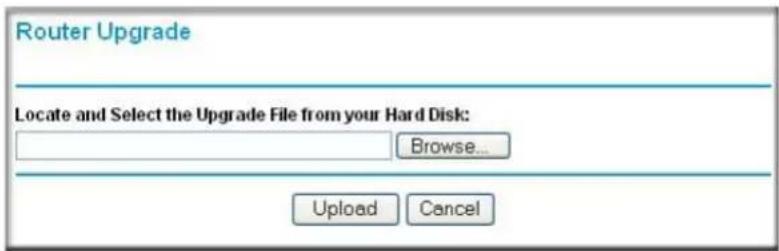
text_image
Router Upgrade Locate and Select the Upgrade File from your Hard Disk: Browse... Upload CancelFigure 6-8: Router Upgrade menu
To upload new firmware:
- Download and unzip the new software file from NETGEAR.
- In the Router Upgrade menu, click the Browse button and locate the upgrade file.
- Click Upload.
Note: When uploading software to the Wireless Range Extender Kit, it is important not to interrupt the Web browser by closing the window, clicking a link, or loading a new page. If the browser is interrupted, it may corrupt the software. When the upload is complete, your router automatically restarts. The upgrade process typically takes about one minute.
In some cases, you may need to reconfigure the router after upgrading.
Chapter 7
Advanced Configuration of the WGX102
This chapter describes how to configure the advanced features of your 54 Mbps Wall-Plugged Wireless Range Extender Kit WGBX102 in Router Mode. These features can be found under the Advanced heading in the main menu of the browser interface.

Note: If you are unfamiliar with networking and routing, refer to Appendix B, "Network, Routing, Firewall, and Basics", to become more familiar with the terms and procedures used in this chapter.
- If you are using the Wireless Range Extender Kit in Access Point Mode, the only Advanced menu option is LAN IP Setup and the configuration options are different than the Router Mode options. See “Configuring the LAN IP Setup Options in Access Point Mode” on page 3-16 for more information.
- If you are using the Wireless Range Extender Kit in Router Mode, you will see additional Advanced features such as Port Forwarding and Triggering, WAN Setup, Dynamic DNS, Static Routes, Remote Management, and UPnP. These features are described in the following sections.
Wireless Range Extender Kit WGX102 Operating Modes
The WGX102 can be immediately used without configuration in Access Point Mode, or can perform more functions in Router Mode. With Router Mode installation, the WGX102 functions as the only router in the network.
Default: Access Point Mode
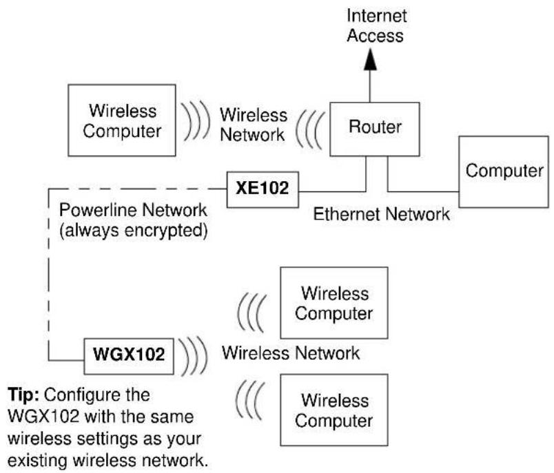
flowchart
graph TD
    A["Computer"] --> B["XE102"]
    B --> C["Router"]
    C --> D["Wireless Computer"]
    C --> E["Wireless Network"]
    F["Wireless Computer"] --> G["WGX102"]
    G --> H["Powerline Network (always encrypted)"]
    H --> I["Wireless Network"]
    I --> J["Internet Access"]
    style A fill:#f9f,stroke:#333
    style F fill:#f9f,stroke:#333
    style G fill:#ccf,stroke:#333
    style H fill:#cfc,stroke:#333
    style I fill:#fcc,stroke:#333
    style J fill:#cff,stroke:#333
Figure 7-1: Access Point mode
In Access Point Mode, the WGX102 acts as an Access Point for your wireless devices. To use the WGX102 in Access Point Mode, you will need to have another device such as a router with DHCP enabled and a working Internet connection in order to access the Internet through the WGX102.
Advanced Custom Setup: Router Mode

flowchart
graph LR
    A["Powerline Network (always encrypted)"] --> B["XE102"]
    C["WGX102"] --> D["Wireless Computer"]
    C --> E["Wireless Network"]
    F["Cable/DSL Modem"] --> G["Internet Access"]
    H["Wireless Computer"] --> I["Wireless Network"]
Figure 7-2: Router mode
In Router Mode, the WGX102 provides all the functions of Access Point Mode, plus the following services:
- Shared Internet Access — the wall plug port becomes the WAN port, and if a broadband modem is connected to it through an XE102, the WGX102 can provide Internet access to your entire wireless LAN.
- DHCP Server — the WGX102 can act as DHCP (Dynamic Host Configuration Protocol) server, which provides the IP address and other TCP/IP configuration for the all the computers that are connected to the wireless range extender through the wireless network. In Router Mode, using this feature is recommended, and it is enabled by default.
Router Mode WGX102 Internet Connection Setup
This section describes how to set up the WGBX102 as the only router on your local area network (LAN) and connect to the Internet. If you already have another router on your LAN, you do not need to configure the WGBX102 in Router Mode and do not need to read this section. The figure below illustrates the 54 Mbps Wall-Plugged Wireless Range Extender Kit WGBX102 in Router Mode:

flowchart
graph TD
    A["Internet"] --> B["Cable/DSL Modem"]
    B --> C["XE102"]
    C --> D["Ethernet"]
    D --> E["Electrical"]
    E --> F["WGX 102 Router Mode"]
    style A fill:#f9f,stroke:#333
    style B fill:#ccf,stroke:#333
    style C fill:#cfc,stroke:#333
    style D fill:#fcc,stroke:#333
    style E fill:#cff,stroke:#333
    style F fill:#ffc,stroke:#333
Figure 7-3: WGB102 in Router Mode
Warning: In router mode, you can only use one XE102 bridge. You cannot have any other XE102 bridges on the same network.
Follow these instructions to set up your wireless range extender in router mode.
1. CONNECT TO THE WIRELESS RANGE EXTENDER KIT
a. Disconnect any existing powerline devices.
b. Plug in the WGXB102 near a wireless computer.

text_image
WGX102 Wireless Notebook PCFigure 7-4: WGX102 plugged in near a wireless computer
c. Turn on your wireless computer.
d. View your computer's Network Connections and right-click on your LAN connection.
e. Go to the Properties screen and select TCP/IP Properties.
f. Configure the wireless computer to use the fixed IP address 192.168.0.210. See Appendix C, "Preparing Your Network" for more information on TCP/IP configuration.
2. CONFIGURE YOUR COMPUTER'S WIRELESS ADAPTER SETTINGS
a. Start your computer's wireless utility program.
b. NETGEAR, Inc. wireless adapters display a list of available wireless networks, and, when wireless security is disabled, you simply choose yours from the list on the Networks tab and click Connect. On the Settings tab page, NETGEAR is the default Network Name (SSID) and security is initially disabled by default, as shown below.

text_image
Profiles Save Profile Delete Profile Network Name(SSID) NETGEAR Advanced Settings Security Disabled WPA-PSK (8-63 characters) WEP Create with Passphrase: Passphrase: 64 bits Enter Key Manually: Key 1: 64 bits Network Type Access Point (Infrastructure) Computer-to-computer (Ad Hgc) Initiate Ad Hoc NETGEAR (00-09-5B-8S-61-62) Internet Connected Ch: 11 48Mbps SignalFigure 7-5: NETGEAR Adapter screen, Settings page
c. For a non-NETGEAR wireless adapter, configure it to match your settings exactly. If you changed the default Network Name (SSID), be sure to use the correct Network Name (SSID) you set in the wireless range extender.
| WIRELESS FEATURE DEFAULT SETTING | |
| Network Name (SSID) NETGEAR | |
| WEP Security Disabled |
Warning: The Network Name (SSID) is case sensitive. Typing nETgear will not work.
Note: Wireless security is disabled by default on the WGXB102. For information about configuring the WGXB102 to use security settings, see Chapter 5, “Wireless Configuration and Security”.
3. LOG IN TO THE WGB102 AND CHANGE TO ROUTER MODE
a. From your wireless computer, open a browser such as Internet Explorer or Netscape® Navigator. Connect to the wireless range extender by typing http://192.168.0.101 in the address field of your browser, then click Enter.
For security reasons, the wireless range extender has its own user name and password. When prompted, enter admin for the user name and password for the password, both in lower case letters. To change the password, see “Changing the Administrator Password” on page 6-7.
Note: The wireless range extender's user name and password are not the same as any user name or password you may use to log in to your Internet connection.
b. From the main menu, select AP/Router Mode to change from Access Point Mode to Router Mode, as shown in the figure “WGB102 in Router Mode” on page 7-4. Select Router Mode and click Apply.
c. You will need to reconnect to continue the configuration after performing the next step.
4. CONNECT THE WIRELESS WALL-PLUGGED BRIDGE AND THE MODEM
a. Look at the bottom of the XE102 bridge to locate the LAN port. Securely insert the Ethernet cable from your modem into the Ethernet port of the XE102 as shown in the diagram below.
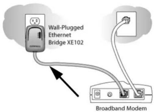
text_image
Wall-Plugged Ethernet Bridge XE102 Broadband ModemFigure 7-6: Connect the bridge to the modem
b. Make sure the WGX102 is plugged in securely to a power outlet.
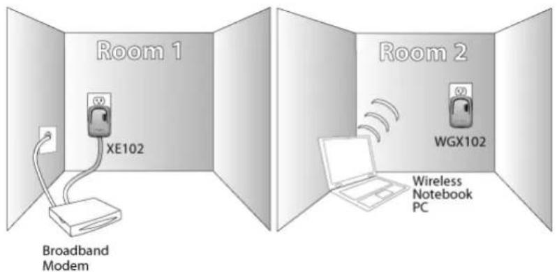
text_image
Room 1 XE102 Broadband Modem Room 2 WGX102 Wireless Notebook PCFigure 7-7: XE102 and WGXB102 directly connected to power outlets
Your network cables are connected and you are ready to restart your network.
5. USE THE SMART WIZARD TO CONFIGURE THE WIRELESS RANGE EXTENDER
a. From a wireless computer, open a browser such as Internet Explorer or Netscape® Navigator. Connect to the wireless range extender by typing http://192.168.0.101 in the address field of your browser, then click Enter.
For security reasons, the wireless range extender has its own user name and password. When prompted, enter admin for the user name and password for the password, both in lower case letters. To change the password, see “Changing the Administrator Password” on page 6-7.
Note: The wireless range extender's user name and password are not the same as any user name or password you may use to log in to your Internet connection.
b. The wireless range extender automatically displays the NETGEAR Setup Wizard configuration assistant the first time you connect in Router Mode, as shown below:
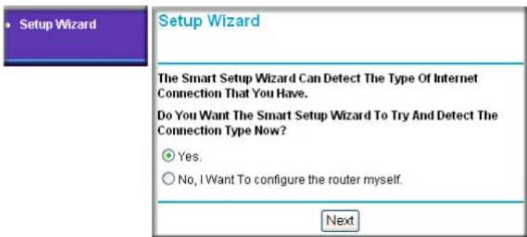
text_image
Setup Wizard The Smart Setup Wizard Can Detect The Type Of Internet Connection That You Have. Do You Want The Smart Setup Wizard To Try And Detect The Connection Type Now? Yes. No, I Want To configure the router myself. NextFigure 7-8: NETGEAR Smart Wizard configuration assistant
Note: If you do not see this page, click Setup Wizard in the main menu on the left.
If you cannot connect to the wireless range extender, verify your computer networking setup. Your wireless computer should be set to obtain both IP and DNS server addresses automatically, which is usually so. For help with this, see Appendix C, "Preparing Your Network" or the animated tutorials on the CD.
c. Click OK. Follow the prompts to proceed with the Smart Wizard configuration assistant to connect to the Internet.
You are now connected to the Internet and the wireless feature of the wireless range extender is enabled!
Note: If you have trouble connecting to the Internet, see “Basic Installation Troubleshooting Tips” on page 3-9 to correct basic problems. You can also manually configure your Internet settings, as described in “Router Mode Manual Internet Connection Configuration” on page 7-10.
6. CONFIGURE YOUR WIRELESS COMPUTERS TO OBTAIN IP ADDRESSES DYNAMICALLY
a. View your computer's Network Connections and right-click on your LAN connection.
b. Go to the Properties screen and select TCP/IP.
c. Click the Properties button.
d. Select “Obtain an IP address automatically” and “Obtain DNS server address automatically. Click OK.
e. Click OK again to save your settings.
Note: See Appendix C, "Preparing Your Network" for more information on TCP/IP configuration.
Router Mode Manual Internet Connection Configuration
You can manually configure your wireless range extender by selecting Basic Settings from the main menu of the browser interface. The screen will change according to which Internet connection type you select, as shown below:
ISP Does Not Require Login
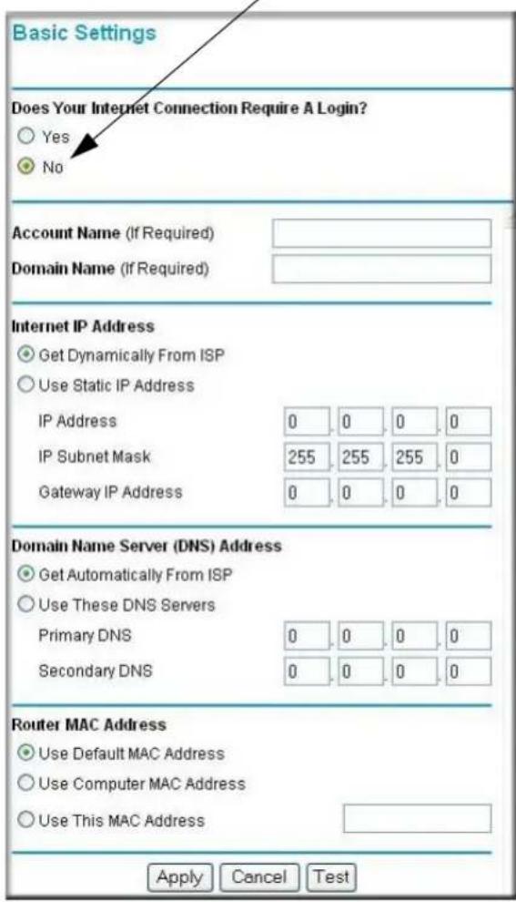
text_image
Basic Settings Does Your Internet Connection Require A Login? Yes No Account Name (If Required) Domain Name (If Required) Internet IP Address Get Dynamically From ISP Use Static IP Address IP Address 0 0 0 0 IP Subnet Mask 255 255 255 0 Gateway IP Address 0 0 0 0 Domain Name Server (DNS) Address Get Automatically From ISP Use These DNS Servers Primary DNS 0 0 0 0 Secondary DNS 0 0 0 0 Router MAC Address Use Default MAC Address Use Computer MAC Address Use This MAC Address Apply Cancel TestISP Does Require Login

text_image
Basic Settings Does Your Internet Connection Require A Login? Yes No Internet Service Provider Login Password Service Name (If Required) Idle Timeout (In Minutes) 5 Domain Name Server (DNS) Address Got Automatically From ISP Use These DNS Servers Primary DNS Secondary DNS Apply Cancel TestFigure 7-9: Browser-based configuration Basic Settings menus
You can manually configure the WGB102 using the Basic Settings menu shown in Figure 7-9 using these steps:
- Connect to the wireless range extender by typing http://192.168.0.101 in the address field of your browser, then click Enter.
- For security reasons, the wireless range extender has its own user name and password. When prompted, enter admin for the user name and password for the password, both in lower case letters.
- Click Basic Settings on the Setup menu.
-
If your Internet connection does not require a login, click No at the top of the Basic Settings menu and fill in the settings according to the instructions below. If your Internet connection does require a login, click Yes, and skip to step 5.
a. Enter your Account Name (may also be called Host Name) and Domain Name. These parameters may be necessary to access your ISP's services such as mail or news servers.
b. Internet IP Address:
If your ISP has assigned you a permanent, fixed (static) IP address for your computer, select “Use Static IP address”. Enter the IP address that your ISP assigned. Also enter the IP Subnet Mask and the Gateway IP address. The Gateway is the ISP’s router to which your wireless range extender will connect. For the Internet IP address, “Get Dynamically From ISP” is selected by default.
c. Domain Name Server (DNS) Address:
If you know that your ISP does not automatically transmit DNS addresses to the wireless range extender during login, select “Use these DNS servers” and enter the IP address of your ISP’s Primary DNS Server. If a Secondary DNS Server address is available, enter it also.
Note: If you enter an address here, restart the computers on your network so that these settings take effect.
d. Router's MAC Address:
This section determines the Ethernet MAC address that will be used by the wireless range extender on the Internet port. Some ISPs register the Ethernet MAC address of the network interface card in your computer when your account is first opened. They will then only accept traffic from the MAC address of that computer. This feature allows your wireless range extender to masquerade as that computer by “cloning” its MAC address.
To change the MAC address, select “Use this Computer’s MAC address”. The wireless range extender then captures and uses the MAC address of the computer that you are now using. You must be using the one computer that is allowed by the ISP. Or, select “Use this MAC address” and type it in here.
e. Click Apply to save your settings. -
If your Internet connection does require a login, fill in the settings according to the instructions below.
a. Select your Internet service provider from the drop-down list. Your choices are:
- PPPoE — if you have installed PPP software such as WinPoET (from Earthlink) or Enternet (from Pacbell), then you are using PPPoE. For more information, see “Manual PPPoE Configuration” on page 7-12.
- PPTP — this protocol is used in Austria and other European countries. For more information, see “Manual PPTP Configuration” on page 7-13.
b. The screen changes according to the ISP settings requirements of the ISP you select.
c. Fill in the parameters for your Internet service provider.
d. Click Apply to save your settings. Click the Test button to verify you have Internet access.
Manual PPPoE Configuration
If your ISP uses PPPoE, select PPPoE for the Internet Service Provider.
- Enter the Account Name, Domain Name, Login, and Password as provided by your ISP. These fields are case sensitive. The wireless range extender tries to discover the domain automatically if you leave the Domain Name blank. Otherwise, you may need to enter it manually.
- To change the login timeout, enter a new value in minutes. This determines how long the wireless range extender keeps the Internet connection active after there is no Internet activity from the LAN. Entering a timeout value of zero means never log out.
Note: You no longer need to run the ISP's login program on your PC in order to access the Internet. When you start an Internet application, your wireless range extender automatically logs you in.
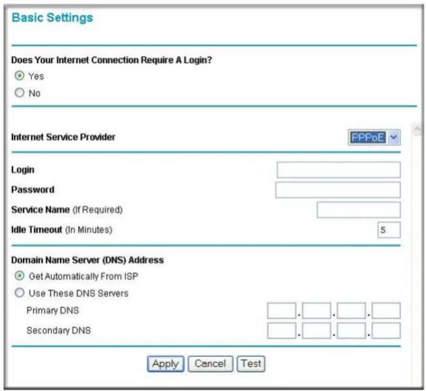
text_image
Basic Settings Does Your Internet Connection Require A Login? Yes No Internet Service Provider FPPoE Login Password Service Name (If Required) Idle Timeout (In Minutes) 5 Domain Name Server (DNS) Address Get Automatically From ISP Use These DNS Servers Primary DNS Secondary DNS Apply Cancel TestFigure 7-10: PPPoE menu
- If you know that your ISP does not automatically transmit DNS addresses to the wireless range extender during login, select “Use these DNS servers” and enter the IP address of your ISP’s Primary DNS Server. If a Secondary DNS Server address is available, enter it also. Note: If you enter DNS addresses, restart your computers so that these settings take effect.
- Click Apply to save your settings. - Click Test to verify that your Internet connection works. If the NETGEAR Web site does not appear within one minute, refer to Chapter 8, “Troubleshooting”.
Manual PPTP Configuration
If your ISP uses PPTP, select PPTP for the Internet Service Provider and you will see the following menu:
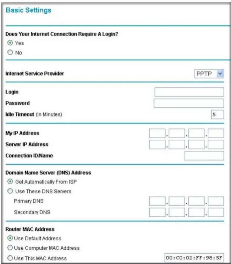
text_image
Basic Settings Does Your Internet Connection Require A Login? Yes No Internet Service Provider PPTP Login Password Idle Timeout (In Minutes) 5 My IP Address Server IP Address Connection ID/Name Domain Name Server (DNS) Address Get Automatically From ISP Use These DNS Servers Primary DNS Secondary DNS Router MAC Address Use Default Address Use Computer MAC Address Use This MAC Address 00:C0:02:FF:98:5FFigure 7-11: PPTP menu
- Enter your Login and Password. These fields are case sensitive.
- To change the login timeout, enter a new value in minutes. This determines how long the wireless range extender keeps the Internet connection active after there is no Internet activity from the LAN. Entering a timeout value of zero means never log out.
Note: You no longer need to run the ISP's login program on your PC in order to access the Internet. When you start an Internet application, your wireless range extender automatically logs you in. The Domain Name Server (DNS) Address parameters may be necessary to access your ISP's services such as mail or news servers.
- Enter your IP address if your ISP provided a fixed IP address, such as 10.0.1.20. Otherwise, leave the IP address set to 0.0.0.0 and you will be automatically assigned an IP address when you connect.
- Enter a Server IP Address is your ISP provided one, such as 10.0.0.138. Otherwise, leave the IP address set to 0.0.0.0 and the Server IP Address will be automatically supplied when you connect.
- Normally the Connection ID/Name should be left blank. If your ISP provided one, then enter it here.
- If you know that your ISP does not automatically transmit DNS addresses to the wireless range extender during login, select “Use these DNS servers” and enter the IP address of your ISP’s Primary DNS Server. If a Secondary DNS Server address is available, enter it also.
Note: If you enter DNS addresses, restart your computers so that these settings take effect. - The Router MAC Address section determines the Ethernet MAC address that will be used by the wireless range extender on the Internet port. Some ISPs register the Ethernet MAC address of the network interface card in your PC when your account is first opened. They will then only accept traffic from the MAC address of that PC. This feature allows your wireless range extender to masquerade as that PC.
To change the MAC address, select “Use this Computer’s MAC address.” The wireless range extender then captures and uses the MAC address of the PC that you are now using. You must be using the one PC that is allowed by the ISP. Or, select “Use this MAC address” and enter it. - Click Apply to save your settings.
- Click Test to test your Internet connection. If the NETGEAR Web site does not appear within one minute, refer to Chapter 8, “Troubleshooting”.
Configuring the WGX102 in Router Mode
The figure below shows the menu choices available when the WGX102 is in Router Mode.

text_image
Setup Wizard Setup AP/Router Mode Basic Settings Wall Plug Settings Wireless Settings Content Filtering Logs Block Sites Block Services Schedule E-mail Maintenance Router Status Attached Devices Backup Settings Set Password Router Upgrade Advanced Port Forwarding Port Triggering WAN Setup LAN IP Setup Dynamic DNS Static Routes Remote Management UPnP Web Support Knowledge Base Documentation LogoutFigure 7-12: Router Mode menu
Router Mode Port Triggering
Port Triggering is an advanced feature that can be used to easily enable gaming and other internet applications. Port Forwarding is typically used to enable similar functionality, but it is static and has some limitations.
Note: If you use applications such as multi-player gaming, peer-to-peer connections, real time communications such as instant messaging, or remote assistance (a feature in Windows XP), you should also enable UPnP according to the instructions at “Router Mode Universal Plug and Play (UPnP)” on page 7-33.
Port Triggering opens an incoming port temporarily and does not require the server on the Internet to track your IP address if it is changed by DHCP, for example. Port Triggering monitors outbound traffic. When the wireless range extender detects traffic on the specified outbound port, it remembers the IP address of the computer that sent the data and triggers the incoming port. Incoming traffic on the triggered port is then forwarded to the triggering computer.
Using the Port Triggering page, you can make local computers or servers available to the Internet for different services (for example, FTP or HTTP), to play Internet games (like Quake III), or to use Internet applications (like CUseeMe).
Port Forwarding is designed for FTP, Web Server or other server based services. Once port forwarding is set up, requests from the Internet are forwarded to the proper server. On the contrary, port triggering only allows request from Internet after a designated port is 'triggered'. Port triggering applies to chat and Internet games.
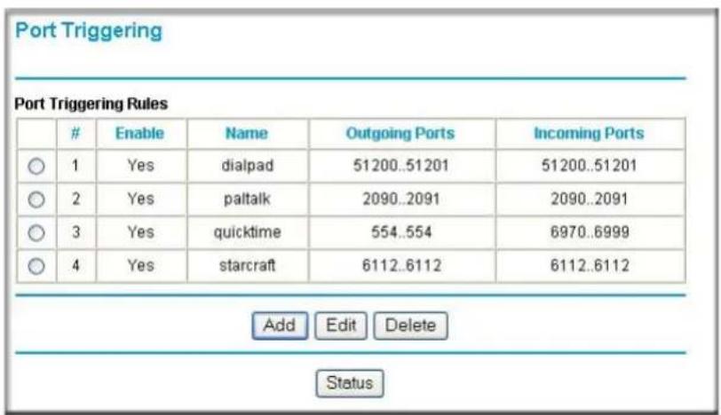
text_image
Port Triggering Port Triggering RulesEnable Name Outgoing Ports Incoming Ports
○ 1 Yes dialpad 51200..51201 51200..51201 ○ 2 Yes paltalk 2090..2091 2090..2091 ○ 3 Yes quicktime 554..554 6970..6999 ○ 4 Yes starcraft 6112..6112 6112..6112 Add Edit Delete StatusFigure 7-13: Port Triggering menu
This table lists the current rules:
- Enable — indicates if the rule is enabled or disabled. Generally, there is no need to disable a rule unless it interferes with some other function, such as Port Forwarding.
- Name — the name for this rule.
- Outgoing Ports — the port or port range for outgoing traffic. An outgoing connection using one of these ports “Triggers” this rule.
- Incoming Ports — the port or port range used by the remote system when it responds to the outgoing request. A response using one of these ports is forwarded to the PC that triggered this rule.
To see which rules are currently being used, click the Status button. The following data is displayed:
- Rule — the name of the Rule.
- LAN IP Address — the IP address of the PC currently using this rule.
- Open Ports — the Incoming ports which are associated the this rule. Incoming traffic using one of these ports is sent to the IP address above.
- Time Remaining — the time remaining before this rule is released, and thus available for other PCs. This timer is restarted whenever incoming or outgoing traffic is received.
Before starting to configure an Internet Game or Application, you need to know which service, application or game you will be configuring. Also, you need to have the outbound port (triggering port) address for this game or application.
Follow these steps to set up a computer to play Internet games or use Internet applications:
- Click Add.
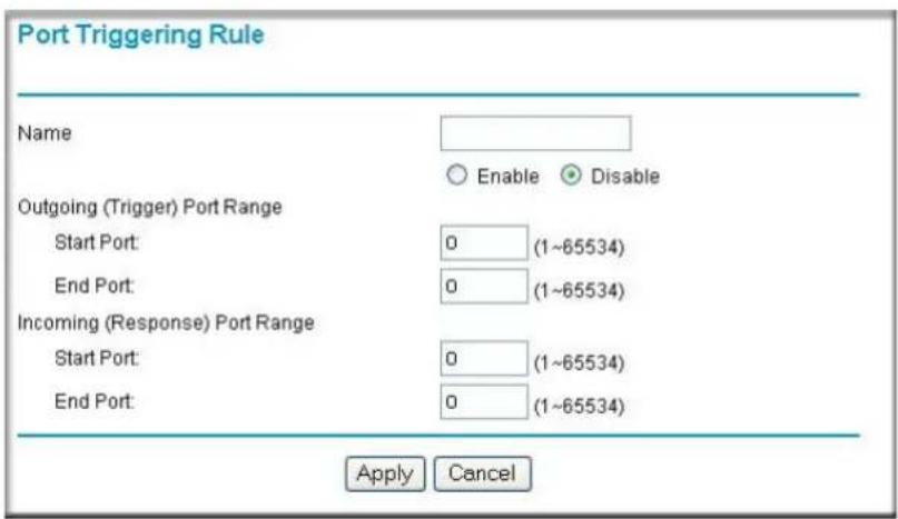
text_image
Port Triggering Rule Name Enable Disable Outgoing (Trigger) Port Range Start Port: 0 (1~65534) End Port: 0 (1~65534) Incoming (Response) Port Range Start Port: 0 (1~65534) End Port: 0 (1~65534) Apply CancelFigure 7-14: Add Port Triggering Rule menu
- For the Name, enter a suitable name for this rule (the name of the application).
- Enable the rule.
- For the Outgoing (Trigger) Port Range, enter the range of port numbers used by the application when it generates an outgoing request.
- For the Incoming (Response) Port Range, enter the range of port numbers used by the remote system when it responds to the PC's request.
- Click Apply to save your changes.
Router Mode Port Forwarding to Local Servers
Although the wireless range extender causes your entire local network to appear as a single machine to the Internet, you can make a local server (for example, a Web server or game server) visible and available to the Internet. This is done using the Port Forwarding menu. From the main
menu of the browser interface, under Advanced, click Port Forwarding to view the port forwarding menu, shown below.

text_image
Port Forwarding Service Name Server IP Address FTP 192 168 0 Add #Service Name Start Port End Port Server IP Address Edit Service Delete Service Add Custom ServiceFigure 7-15: Port Forwarding menu
Use the Port Forwarding menu to configure the wireless range extender to forward incoming protocols to computers on your local network. In addition to servers for specific applications, you can also specify a Default DMZ Server to which all other incoming protocols are forwarded. The DMZ Server is configured in the WAN Setup menu as discussed in “Router Mode WAN Setup Options” on page 7-23.
Before starting, you need to determine which type of service, application or game you will provide and the IP address of the computer that will provide each service. Be sure the computer's IP address never changes. To configure port forwarding to a local server:

Note: To assure that the same computer always has the same IP address, use the reserved IP address feature of your Wireless Range Extender Kit. See “Using Address Reservation in Router Mode” on page 7-28 for instructions on how to use reserved IP addresses.
- From the Service & Game box, select the service or game to host on your network.
If the service does not appear in the list, refer to the following section, "Adding a Custom Service". - Enter the IP address of the local server in the corresponding Server IP Address box.
- Click the Add button.
Adding a Custom Service
To define a service, game or application that does not appear in the Services & Games list, you must determine what port numbers are used by the service. For this information, you may need to contact the manufacturer of the program that you wish to use. When you have the port number information, follow these steps:
- Click the Add Custom Service button.

text_image
Ports - Custom Services Service Name Starting Port (1~65534) Ending Port (1~65534) Server IP Address 192 168 0 Apply CancelFigure 7-16: Ports - Custom Services menu
- Type the service name in the Service Name box.
-
Type the beginning port number in the Starting Port box.
-
If the application uses only a single port; type the same port number in the Ending Port box.
-
If the application uses a range of ports; type the ending port number of the range in the Ending Port box.
-
Type the IP address of the computer in the Server IP Address box.
-
Click Apply to save your changes.
Local Web and FTP Server Example
If a local computer with a private IP address of 192.168.0.33 acts as a Web and FTP server, configure the Ports menu to forward HTTP (port 80) and FTP (port 21) to local address 192.168.0.33.
In order for a remote user to access this server from the Internet, the remote user must know the IP address that has been assigned by your ISP. If this address is 172.16.1.23, for example, an Internet user can access your Web server by directing the browser to http://172.16.1.23. The assigned IP address can be found in the Router Status menu, where it is shown as the WAN IP Address.
Some considerations for this application are:
- If your account's IP address is assigned dynamically by your ISP, the IP address may change periodically as the DHCP lease expires.
- If the IP address of the local computer is assigned by DHCP, it may change when the computer is rebooted. To avoid this, you can manually configure the computer to use a fixed address.
- Local computers must access the local server using the computers' local LAN address (192.168.0.33 in this example). Attempts by local computers to access the server using the external IP address (172.16.1.23 in this example) will fail.
Multiple Computers for Half Life, KALI or Quake III Example
To set up an additional computer to play Half Life, KALI or Quake III:
- Click the button of an unused port in the table.
- Select the game again from the Services/Games list.
-
Change the beginning port number in the Start Port box.
For these games, use the supplied number in the default listing and add +1 for each additional computer. For example, if you've already configured one computer to play Hexen II (using port 26900), the second computer's port number would be 26901, and the third computer would be 26902. -
Type the same port number in the End Port box that you typed in the Start Port box.
-
Type the IP address of the additional computer in the Server IP Address box.
-
Click Apply.
Some online games and videoconferencing applications are incompatible with NAT. The Wireless Range Extender Kit is programmed to recognize some of these applications and to work properly with them, but there are other applications that may not function well. In some cases, one local computer can run the application properly if that computer's IP address is entered as the default in the Ports menu. If one local computer acts as a game or videoconferencing host, enter its IP address as the default.
Router Mode WAN Setup Options
The WAN Setup options let you configure a DMZ server, change the MTU size and enable the wireless range extender to respond to a Ping on the WAN port. These options are discussed below.

text_image
WAN Setup Connect Automatically, as Required Disable SPI Firewall Default DMZ Server 192 . 168 . 1 . 0 Respond to Ping on Internet Port MTU Size (in bytes) 1500 Apply CancelFigure 7-17: WAN Setup menu.
Connect Automatically, as Required. Normally, this option should be selected. An Internet connection will be made automatically after each timeout, whenever Internet-bound traffic is detected. This provides connection on demand and is potentially cost-saving in places in Europe for example where Internet services charge by the minute.
If disabled, you must connect manually, using the Connection Status button on the Router Status screen. This manual connection stays up all the time without timeouts.
Disable SPI Firewall. The Stateful Packet Inspection (SPI) Firewall protects your LAN against Denial of Service attacks. This should only be disabled in special circumstances.
Default DMZ Server. The default DMZ server feature is helpful when using some online games and videoconferencing applications that are incompatible with NAT. The WGX102 is programmed to recognize some of these applications and to work properly with them, but there are other applications that may not function well. In some cases, one local computer can run the application properly if that computer's IP address is entered as the default DMZ server.

Note: DMZ servers pose a security risk. A computer designated as the default DMZ server loses much of the protection of the firewall, and is exposed to exploits from the Internet. If compromised, the DMZ server can be used to attack your network.
Incoming traffic from the Internet is normally discarded by the WGX102 unless the traffic is a response to one of your local computers or a service that you have configured in the Ports menu. Instead of discarding this traffic, you can have it forwarded to one computer on your network. This computer is called the Default DMZ Server.
To assign a computer or server to be a Default DMZ server, follow these steps:
- Click WAN Setup link on the Advanced section of the main menu.
- Type the IP address for that server. To remove the default DMZ server, replace the IP address numbers with all zeros.
- Click Apply.
Respond to Ping on Internet WAN Port. If you want the WGX102 to respond to a 'ping' from the Internet, select the Respond to Ping on Internet WAN Port check box. This should only be used as a diagnostic tool, since it allows your wireless range extender to be discovered. Do not select this check box unless you have a specific reason to do so.
MTU Size. The normal MTU (Maximum Transmit Unit) value for most Ethernet networks is 1500 Bytes, 1492 Bytes for PPPoE connections, or 1436 for PPTP connections. For some ISPs you may need to reduce the MTU. But this is rarely required, and should not be done unless you are sure it is necessary for your ISP connection.
Any packets sent through the wireless range extender that are larger than the configured MTU size are repackaged into smaller packets to meet the MTU requirement. To change the MTU size:
- Under MTU Size, enter a new size between 64 and 1500.
- Click Apply to save the new configuration.
Router Mode LAN IP Setup Options
LAN IP Setup is under the Advanced heading on both the Access Point Mode and Router Mode menus. If you are using the WGX102 in Access Point Mode, see “Configuring the LAN IP Setup Options in Access Point Mode” on page 3-16 for configuration information.
This menu allows configuration of LAN IP services such as DHCP and RIP in Router Mode. From the main menu of the browser interface, under Advanced, click LAN IP Setup to view the LAN IP Setup menu, shown below.
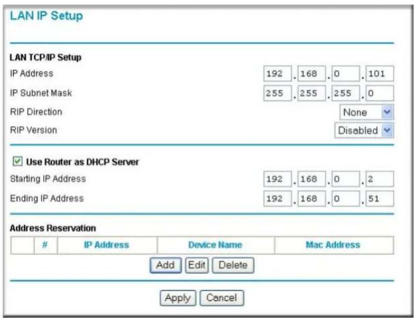
text_image
LAN IP Setup LAN TCP/IP Setup IP Address 192 . 168 . 0 . 101 IP Subnet Mask 255 . 255 . 255 . 0 RIP Direction None RIP Version Disabled ✓ Use Router as DHCP Server Starting IP Address 192 . 168 . 0 . 2 Ending IP Address 192 . 168 . 0 . 51 Address ReservationIP Address Device Name Mac Address
Add Edit Delete Apply CancelFigure 7-18: LAN IP Setup menu in Router Mode
The wireless range extender's default LAN IP configuration is:
• LAN IP addresses—192.168.0.101
- Subnet mask—255.255.255.0
These addresses are part of the IETF-designated private address range for use in private networks, and should be suitable in most applications. If your network has a requirement to use a different IP addressing scheme, you can make those changes in this menu.
The LAN IP parameters are:
- IP Address
This is the LAN IP address of the wireless range extender.
- IP Subnet Mask
This is the LAN Subnet Mask of the wireless range extender. Combined with the IP address, the IP Subnet Mask allows a device to know which other addresses are local to it, and which must be reached through a gateway or router.
- RIP Direction
RIP (Router Information Protocol) allows a router to exchange routing information with other routers. The RIP Direction selection controls how the WGB102 sends and receives RIP packets. Both is the default.
— When set to Both or Out Only, the WGX102 broadcasts its routing table periodically.
— When set to Both or In Only, it incorporates the RIP information that it receives.
— When set to None, it does not send any RIP packets and ignores any RIP packets received.
- RIP Version
This controls the format and the broadcasting method of the RIP packets that the WGX102 sends. (It recognizes both formats when receiving.) By default, this is set for RIP-1.
— RIP-1 is universally supported. RIP-1 is probably adequate for most networks, unless you have an unusual network setup.
— RIP-2 carries more information. Both RIP-2B and RIP-2M send the routing data in RIP-2 format.
- RIP-2B uses subnet broadcasting.
- RIP-2M uses multicasting. Multicasting can reduce the load on non-router machines because they do not listen to the RIP multicast address and do not receive the RIP packets. However, if one router uses multicasting, then all routers on your network must use multicasting.

Note: If you change the LAN IP address of the WGX102 while connected through the browser, you will be disconnected. You must then open a new connection to the new IP address and log in again.
Using the WGX102 in Router Mode as a DHCP server
By default, the WGX102 functions as a DHCP (Dynamic Host Configuration Protocol) server, allowing it to assign IP, DNS server, and default gateway addresses to all computers connected to the wireless range extender's LAN. The assigned default gateway address is the LAN address of the WGX102 IP addresses are assigned to the attached computers from a pool of addresses specified in this menu. Each pool address is tested before it is assigned to avoid duplicate addresses on the LAN.
For most applications, the default DHCP and TCP/IP settings of the wireless range extender are satisfactory. See “IP Configuration by DHCP” on page B-10 for an explanation of DHCP and information about how to assign IP addresses for your network.
If another device on your network is the DHCP server, or if you manually configure the network settings of all of your computers, clear the ‘Use router as DHCP server’ check box. Otherwise, leave it selected.
To specify the pool of IP addresses to be assigned, set the Starting IP Address and Ending IP Address. These addresses should be part of the same IP address subnet as the wireless range extender's LAN IP address. Using the default addressing scheme, you should define a range between 192.168.0.2 and 192.168.0.253, although you may want to save part of the range for devices with fixed addresses.
The WGB102 delivers the following parameters to any LAN device that requests DHCP:
- An IP Address from the range you have defined
- Subnet Mask
- Gateway IP Address (the wireless range extender's LAN IP address)
- Primary DNS Server (if you entered a Primary DNS address in the Basic Settings menu; otherwise, the wireless range extender's LAN IP address)
- Secondary DNS Server (if you entered a Secondary DNS address in the Basic Settings menu)
Using Address Reservation in Router Mode
When you specify a reserved IP address for a computer on the LAN, that computer always receives the same IP address each time it accesses the wireless range extender's DHCP server. Reserved IP addresses should be assigned to servers that require permanent IP settings.
To reserve an IP address:
- Click the Add button.
- In the IP Address box, type the IP address to assign to the computer or server (choose an IP address from the wireless range extender's LAN subnet, such as 192.168.0.x).
- Type the MAC Address of the computer or server. (Tip: If the computer is already present on your network, you can copy its MAC address from the Attached Devices menu and paste it here.)
- Type a Device Name of your choosing.
- Click Apply to enter the reserved address into the table.
Note: The reserved address is not assigned until the next time the computer contacts the wireless range extender's DHCP server. Reboot the computer or access its IP configuration and force a DHCP release and renew.
To edit or delete a reserved address entry:
- Click the button next to the reserved address you want to edit or delete.
- Click Edit or Delete.
Router Mode Dynamic DNS
If your network has a permanently assigned IP address, you can register a domain name and have that name linked with your IP address by public Domain Name Servers (DNS). However, if your Internet account uses a dynamically assigned IP address, you will not know in advance what your IP address will be, and the address can change frequently. In this case, you can use a commercial dynamic DNS service, which allows you to register your domain to their IP address, and forward traffic directed at your domain to your frequently-changing IP address.

Note: If your ISP assigns a private WAN IP address (such as 192.168.x.x or 10.x.x.x), the dynamic DNS service will not work because private addresses will not be routed on the Internet.
The WGX102 contains a client that can connect to many popular dynamic DNS services. You can select one of these services and obtain an account with them. Then, whenever your ISP-assigned IP address changes, your wireless range extender automatically contacts your dynamic DNS service provider, log in to your account, and register your new IP address.
To configure Dynamic DNS:
- From the main menu of the browser interface, under Advanced, click Dynamic DNS.
- Register for an account with one of the dynamic DNS service providers whose names appear in the 'Select Service Provider' box. For example, for dyndns.org, go to http://www.dyndns.org.
- Select the Use a dynamic DNS service check box.
- Select the name of your dynamic DNS Service Provider.
- Type the Host Name (or domain name) that your dynamic DNS service provider gave you.
- Type the User Name for your dynamic DNS account.
- Type the Password (or key) for your dynamic DNS account.
- If your dynamic DNS provider allows the use of wildcards in resolving your URL, you may select the Use wildcards check box to activate this feature.
For example, the wildcard feature causes *.yourhost.dyndns.org to be aliased to the same IP address as yourhost.dyndns.org - Click Apply to save your configuration.
Router Mode Static Routes
Static Routes provide additional routing information to your wireless range extender. Under normal circumstances, the WGX102 has adequate routing information after it has been configured for Internet access, and you do not need to configure additional static routes. You must configure static routes only for unusual cases such as multiple routers or multiple IP subnets located on your network.
From the main menu of the browser interface, under Advanced, click Static Routes to view the Static Routes menu, shown below.
| # | Name | Destination | Gateway |
| 1 | isdn_rtr | 134.177.0.0 | 192.168.0.100 |
| 2 | - | ... | ... |
| 3 | - | ... | ... |
| 4 | - | ... | ... |
| 5 | - | ... | ... |
| 6 | - | ... | ... |
| 7 | - | ... | ... |
| 8 | - | ... | ... |
Figure 7-19. Static Route Summary Table
To add a Static Route:
- Click the Add button to open the Add/Edit menu, shown below:.
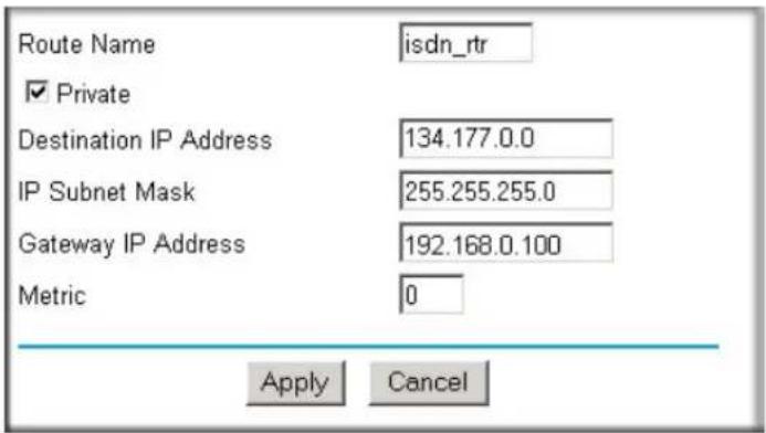
text_image
Route Name isdn_rtr ✓ Private Destination IP Address 134.177.0.0 IP Subnet Mask 255.255.255.0 Gateway IP Address 192.168.0.100 Metric 0 Apply CancelFigure 7-20. Static Route Add/Edit menu
- Type a route name for this static route in the Route Name box under the table. (This is for identification purposes only.)
7-30 Advanced Configuration of the WGX102
- Select Private if you want to limit access to the LAN only. The static route will not be reported in RIP.
- Select Active to make this route effective.
- Type the Destination IP Address of the final destination.
- Type the IP Subnet Mask for this destination. If the destination is a single host, type 255.255.255.255.
- Type the Gateway IP Address, which must be a router on the same LAN segment as the WGX102.
- Type a number between 1 and 15 as the Metric value. This represents the number of routers between your network and the destination. Usually, a setting of 2 or 3 works, but if this is a direct connection, set it to 1.
- Click Apply to have the static route entered into the table.
As an example of when a static route is needed, consider the following case:
- Your primary Internet access is through a cable modem to an ISP.
- You have an ISDN router on your home network for connecting to the company where you are employed. This router's address on your LAN is 192.168.0.100.
- Your company's network is 134.177.0.0.
When you first configured your WGX102, two implicit static routes were created. A default route was created with your ISP as the gateway, and a second static route was created to your local network for all 192.168.0.x addresses. With this configuration, if you attempt to access a device on the 134.177.0.0 network, your wireless range extender forwards your request to the ISP. The ISP forwards your request to the company where you are employed, and the request will likely be denied by the company's firewall.
In this case you must define a static route, telling your wireless range extender that 134.177.0.0 should be accessed through the ISDN router at 192.168.0.100. The static route would look like Figure 7-20.
In this example:
- The Destination IP Address and IP Subnet Mask fields specify that this static route applies to all 134.177.x.x addresses.
- The Gateway IP Address fields specifies that all traffic for these addresses should be forwarded to the ISDN router at 192.168.0.100.
- A Metric value of 1 will work since the ISDN router is on the LAN.
- Private is selected only as a precautionary security measure in case RIP is activated.
Router Mode Remote Management Access
Using the Remote Management page, you can allow a user or users on the Internet to configure, upgrade and check the status of your Wireless Range Extender Kit.

Note: Be sure to change the wireless range extender's default configuration password to a very secure password. The ideal password should contain no dictionary words from any language, and should be a mixture of letters (both upper and lower case), numbers, and symbols. Your password can be up to 30 characters.
To configure your wireless range extender for Remote Management:
- Select the Turn Remote Management On check box.
- Specify what external addresses are allowed to access the wireless range extender's remote management.
Note: For enhanced security, restrict access to as few external IP addresses as practical.
a. To allow access from any IP address on the Internet, select Everyone.
b. To allow access from a range of IP addresses on the Internet, select IP address range. Enter a beginning and ending IP address to define the allowed range.
c. To allow access from a single IP address on the Internet, select Only this computer. Enter the IP address that is allowed access.
- Specify the Port Number to use for accessing the management interface.
Web browser access normally uses the standard HTTP service port 80. For greater security, change the remote management Web interface to a custom port by entering that number in the box provided. Choose a number between 1024 and 65535, but do not use the number of any common service port. The default is 8080, which is a common alternate for HTTP.
- Click Apply to have your changes take effect.
Note: When accessing your WGX102 from the Internet, type your wireless range extender's WAN IP address into your browser's Address (in IE) or Location (in Netscape) box, followed by a colon (:) and the custom port number. For example, if your external address is 134.177.0.123 and you use port number 8080, you must enter http://134.177.0.123:8080 in your browser.
Router Mode Universal Plug and Play (UPnP)
Universal Plug and Play (UPnP) helps devices, such as Internet appliances and computers, access the network and connect to other devices as needed. UPnP devices can automatically discover the services from other registered UPnP devices on the network.
From the main menu of the browser interface, under Advanced, click UPnP. Set up UPnP according to the guidelines below.

text_image
UPnP ✓ Turn UPnP On Advertisement Period (in minutes) 30 Advertisement Time To Live (in hops) 0 UPnP Portmap Table Active Protocol Int. Port Ext. Port IP Address Yes TCP 9198 11913 192.168.0.2 Yes UDP 5339 7102 192.168.0.2 Apply Cancel RefreshFigure 7-21. UPnP menu
Turn UPnP On: UPnP can be enabled or disabled for automatic device configuration. The default setting for UPnP is disabled. If disabled, the wireless range extender does not allow any device to automatically control the resources, such as port forwarding (mapping), of the wireless range extender.
Note: If you use applications such as multi-player gaming, peer-to-peer connections, real time communications such as instant messaging, or remote assistance (a feature in Windows XP), you should enable UPnP.
Advertisement Period: The Advertisement Period is how often the WGX102 broadcasts its UPnP information. This value can range from 1 to 1440 minutes. The default period is 30 minutes. Shorter durations ensure that control points have current device status at the expense of additional network traffic. Longer durations may compromise the freshness of the device status but can significantly reduce network traffic.
Advertisement Time To Live: The time to live for the advertisement is measured in hops (steps) for each UPnP packet sent. The time to live hop count is the number of steps a broadcast packet is allowed to propagate for each UPnP advertisement before it disappears. The number of hops can range from 1 to 255. The default value for the advertisement time to live is 4 hops, which should be fine for most home networks. If you notice that some devices are not being updated or reached correctly, then it may be necessary to increase this value a little.
UPnP Portmap Table: The UPnP Portmap Table displays the IP address of each UPnP device that is currently accessing the WGX102 and which ports (Internal and External) that device has opened. The UPnP Portmap Table also displays what type of port is opened and if that port is still active for each IP address.
Router Mode Content Filtering Overview
The 54 Mbps Wall-Plugged Wireless Range Extender Kit WGBX102 provides you with Web content filtering options, plus browsing activity reporting and instant alerts via e-mail. Parents and network administrators can establish restricted access policies based on time of day, Web addresses and Web address keywords. You can also block Internet access by applications and services, such as chat or games.
To configure these features of your wireless range extender, click on the subheadings under the Content Filtering heading in the main menu of the browser interface. The subheadings are described below:
Router Mode Blocking Access to Internet Sites
The Wireless Range Extender Kit allows you to restrict access based on Web addresses and Web address keywords. Up to 255 entries are supported in the Keyword list.
Keyword application examples:
- If the keyword “XXX” is specified, the URL http://www.badstuff.com/xxx.html is blocked.
- If the keyword “.com” is specified, only Web sites with other domain suffixes (such as .edu or .gov) can be viewed.
- If you want to block all Internet browsing access during a scheduled period, enter the keyword “.” and set the schedule in the Schedule menu.
The Block Sites menu is shown in the figure below:

text_image
Block Sites Keyword Blocking Never Per Schedule Always Type keyword or domain name here. Add Keyword Block sites containing these keywords or domain names: discodanny Delete Keyword Clear List Allow Trusted IP Address To Visit Blocked Sites Trusted IP Address 0 0 0 0 Apply CancelFigure 7-22: Block Sites menu
- To enable keyword blocking, select either "Per Schedule" or "Always", then click Apply. If you want to block by schedule, be sure that a time period is specified in the Schedule menu.
- To add a keyword or domain, type it in the Keyword box, click Add Keyword, then click Apply.
• To delete a keyword or domain, select it from the list, click Delete Keyword, then click Apply. - To specify a Trusted User, enter that PC's IP address in the Trusted User box and click Apply. You may specify one Trusted User, which is a PC that is exempt from blocking and logging. Since the Trusted User is identified by an IP address, you should configure that PC with a fixed IP address.
Router Mode Blocking Access to Internet Services
The Wireless Range Extender Kit allows you to block the use of certain Internet services by PCs on your network. This is called services blocking or port filtering. The Block Services menu is shown below:

text_image
Block Services ○ Of ○ Per Schedule ● AlwaysService Type Port IP
○ 1 HTTP 80~80 Every IP Apply Add Edit DeleteFigure 7-23: Block Services menu
Services are functions performed by server computers at the request of client computers. For example, Web servers serve Web pages, time servers serve time and date information, and game hosts serve data about other players' moves. When a computer on your network sends a request for service to a server computer on the Internet, the requested service is identified by a service or port number. This number appears as the destination port number in the transmitted IP packets. For example, a packet that is sent with destination port number 80 is an HTTP (Web server) request.
To enable service blocking, select either Per Schedule or Always, then click Apply. If you want to block by schedule, be sure that a time period is specified in the Schedule menu.
To specify a service for blocking, click Add. The Add Services menu appears, as shown below:
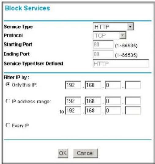
text_image
Block Services Service Type HTTP Protocol TCP Starting Port 80 (1~65535) Ending Port 80 (1~65535) Service Type/User Defined HTTP Filter IP by : ● Only this IP: 192 .168 .0 . ○ IP address range: 192 .168 .0 . to 192 .168 .0 . ○ Every IP OK CancelFigure 7-24: Add Services menu
From the Service Type list, select the application or service to be allowed or blocked. The list already displays several common services, but you are not limited to these choices. To add any additional services or applications that do not already appear, select User Defined.
Configuring a User Defined Service
To define a service, first you must determine which port number or range of numbers is used by the application. The service numbers for many common protocols are defined by the Internet Engineering Task Force (IETF) and published in RFC1700, “Assigned Numbers.” Service numbers for other applications are typically chosen from the range 1024 to 65535 by the authors of the application. This information can usually be determined by contacting the publisher of the application or from user groups of newsgroups.
Enter the Starting Port and Ending Port numbers. If the application uses a single port number, enter that number in both boxes.
If you know that the application uses either TCP or UDP, select the appropriate protocol. If you are not sure, select Both.
Configuring Services Blocking by IP Address Range
Under “Filter Services For”, you can block the specified service for a single computer, a range of computers (having consecutive IP addresses), or all computers on your network.
Router Mode Scheduling When Blocking is Enforced
The Wireless Range Extender Kit allows you to specify when blocking is enforced. The Schedule menu is shown below:

text_image
Schedule Days To Block: ✓ Every day ✓ Sunday ✓ Monday ✓ Tuesday ✓ Wednesday ✓ Thursday ✓ Friday ✓ Saturday Time Of Day To Block: (use 24-hour clock) ✓ All Day Start Blocking: 0 Hour 0 Min End Blocking: 0 Hour 0 Min Apply CancelFigure 7-25: Schedule menu
- Use this schedule for blocking content. Select this check box if you want to enable a schedule for Content Filtering. Click Apply.
- Days to Block. Select days to block by selecting the appropriate check boxes. Select Everyday to select the check boxes for all days. Click Apply.
- Time of Day to Block. Select a start and end time in 23:59 format. Select All day for 24 hour blocking. Click Apply.
Note: Be sure to select your Time Zone in the E-mail menu.
Router Mode Logs of Web Access or Attempted Web Access
The log is a detailed record of what Web sites you have accessed or attempted to access. Up to 128 entries are stored in the log. Log entries only appear when keyword blocking is enabled, and no log entries are made for the Trusted User. An example is shown below:

text_image
Logs 0|Fri, 15 Feb 2002 16:38:14 Source:192.168.0.2 BLOCK:www.yahoo.com 1|Fri, 15 Feb 2002 16:34:07 Source:192.168.0.2 ALLOW:ar.atwola.com 2|Fri, 15 Feb 2002 16:34:06 Source:192.168.0.2 ALLOW:www.cnn.com 3|Fri, 15 Feb 2002 16:34:05 Source:192.168.0.2 ALLOW:toolbar.netscape.com 4|Fri, 15 Feb 2002 16:34:03 Source:192.168.0.2 ALLOW:i.cnn.net 5|Fri, 15 Feb 2002 16:34:02 Source:192.168.0.2 ALLOW:www.cnn.com 6|Fri, 15 Feb 2002 16:33:03 Source:192.168.0.2 ALLOW:i.cnn.net Refresh Clear Log Send LogFigure 7-26: Logs menu
Log entries are described in Table 7-1
Table 7-1. Log entry descriptions
| Field Description | |
| Number The index number of the content filter log entries. Up to 128 entries are available, numbered from 0 to 127. The log keeps a record of the latest 128 entries. | |
| Date and Time The date and time the log entry was recorded. | |
| Source IP The IP address of the initiating device for this log entry. | |
| Action This field displays whether the access was blocked or allowed. | |
| Web site The name or IP address of the Web site or newsgroup visited or attempted to access. | |
Log action buttons are described in Table 7-2
Table 7-2. Log action buttons
| Button Description | |
| Refresh Refresh | the log screen. |
| Clear Log Clear | the log entries. |
| Send Log E-mail | the log immediately. |
Router Mode E-Mail Alert and Web Access Log Notifications
In order to receive logs and alerts by e-mail, you must provide your e-mail information in the E-mail menu, shown below:
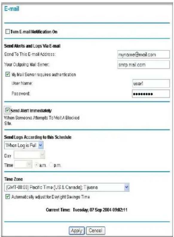
text_image
E-mail Turn E-mail Notification On Send Alerts and Logs Via E-mail Send To This E-mail Address: myname@mail.com Your Outgoing Mail Server: smtp.mail.com My Mail Server requires authentication User Name: user1 Password: ********** Send Alert Immediately When Someone Attempts To Visit A Blocked Site. Send Logs According to this Schedule When Log is Full Day Time a.m. p.m. Time Zone (GMT-08:00) Pacific Time (US & Canada): Tijuene Automatically adjust for Daylight Savings Time Current Time: Tuesday, 07 Sep 2004 09:02:11 Apply CancelFigure 7-27: E-mail menu
- Turn e-mail notification on
Select this check box if you wish to receive e-mail logs and alerts from the WGB102.
- Your outgoing mail server
Enter the name of your ISP's outgoing (SMTP) mail server (such as mail.myISP.com). You may be able to find this information in the configuration menu of your e-mail program. If you leave this box blank, log and alert messages are not sent via e-mail.
- Send to this e-mail address
Enter the e-mail address to which logs and alerts are sent. This e-mail address is also used as the From address. If you leave this box blank, log and alert messages are not sent via e-mail.
You can specify that logs are automatically sent to the specified e-mail address with these options:
- Send alert immediately
Select this check box if you would like immediate notification of attempted access to a blocked site.
- Send logs according to this schedule
Specifies how often to send the logs: Hourly, Daily, Weekly, or When Full.
– Day for sending log
Specifies which day of the week to send the log. Relevant when the log is sent weekly or daily.
– Time for sending log
Specifies the time of day to send the log. Relevant when the log is sent daily or weekly.
If the Weekly, Daily or Hourly option is selected and the log fills up before the specified period, the log is automatically e-mailed to the specified e-mail address. After the log is sent, the log is cleared from the router's memory. If the router cannot e-mail the log file, the log buffer may fill up. In this case, the WGB102 overwrites the log and discards its contents.
The Wireless Range Extender Kit uses the Network Time Protocol (NTP) to obtain the current time and date from one of several Network Time Servers on the Internet. In order to localize the time for your log entries, you must specify your Time Zone:
• Time Zone
Select your local time zone. This setting is used for the blocking schedule and for time-stamping log entries.
• Daylight Savings Time
Select this check box if your time zone is currently under daylight savings time.
Chapter 8
Troubleshooting
This chapter gives information about troubleshooting your 54 Mbps Wall-Plugged Wireless Range Extender Kit WGBX102. After each problem description, instructions are provided to help you diagnose and solve the problem.
NETGEAR Product Registration, Support, and Documentation
Register your product at http://www.netgear.com/register. Registration is required before you can use our telephone support service.
Product updates and Web support are always available by going to: http://kbserver.netgear.com/products/WGXB102.asp.
When the wireless range extender is connected to the Internet, click the Knowledge Base or the Documentation link under the Web Support menu to view support information or the documentation for the wireless range extender.
Basic Functioning
After you turn on power to the WGB102 devices, the following sequence of events should occur:
- When power is first applied, verify that the Power light is on.
- After approximately 10 seconds, verify that:
a. The power light is solid green.
b. The HomePlug port (called the Internet port in Router Mode) light is lit.
c. The Wireless port on the WGX102 or Ethernet port on the XE102 light is lit.
If any of these conditions does not occur, refer to the appropriate following section.
Power Light Not On
If the Power and other lights are off when your wireless range extender is turned on, make sure that the WGX102 and XE102 are properly connected to a functioning power outlet.
If the error persists, you have a hardware problem and should contact technical support.
HomePlug/Internet or Wireless Port Lights Not On
If either the HomePlug/Internet or the Wireless light are not lit, check the following:
- Make sure that the Ethernet cable connection is secure at the XE102 and the router it connects to.
- Be sure you are using the correct cable on the router that the XE102 is connected to. When connecting the router's Internet port to a cable or DSL modem, use the cable that was supplied with the cable or DSL modem. This cable could be a standard straight-through Ethernet cable or an Ethernet crossover cable.
Troubleshooting the Web Configuration Interface
If you are unable to access the wireless range extender's Web Configuration interface from a computer on your local network, check the following:
- Check the Ethernet connection between the computer and the wireless range extender as described in the previous section.
- Make sure your computer's IP address is on the same subnet as the WGX102. If you are using the recommended addressing scheme, your computer's address should be in the range of 192.168.0.2 to 192.168.0.254. Refer to “Verifying TCP/IP Properties” on page C-9 or “Verifying TCP/IP Properties for Macintosh Computers” on page C-20 to find your computer's IP address. Follow the instructions in Appendix C to configure your computer.
Note: If your computer's IP address is shown as 169.254.x.x: Recent versions of Windows and MacOS generate and assign IP addresses if the computer cannot reach a DHCP server. These auto-generated addresses are in the range of 169.254.x.x. If your IP address is in this range, check the connection from the computer to the WGX102 and reboot your computer.
- If the WGX102 IP address has been changed and you do not know the current IP address, clear the wireless range extender's configuration to factory defaults. This sets the wireless range extender's IP address to 192.168.0.101. This procedure is explained in “Restoring the Default WGX102 Configuration and Password” on page 8-7.
- Make sure your browser has Java, JavaScript, or ActiveX enabled. If you are using Internet Explorer, click Refresh to be sure the Java applet is loaded.
- Try quitting the browser and launching it again.
- Make sure you are using the correct login information. The factory default login name is admin and the password is password. Make sure that Caps Lock is off when entering this information.
If the WGX102 does not save changes you have made in the Web browser interface, check the following:
- When entering configuration settings, be sure to click the Apply button before moving to another menu or tab, or your changes will be lost.
- Click the Refresh or Reload button in the Web browser. The configuration changes may have occurred, but the Web browser may be caching the old configuration.
Troubleshooting the Router Mode Only ISP Connection
If your WGX102 is unable to access the Internet, you should first determine whether the WGX102 is able to obtain a WAN IP address from the ISP. Unless you have been assigned a static IP address, your wireless range extender must request an IP address from the ISP. You can determine whether the request was successful using the Web Configuration Manager.
To check the WAN IP address of your NETGEAR wireless range extender:
- Launch your browser and select an external site such as http://www.netgear.com.
- Access the main menu of the wireless range extender's configuration at http://192.168.0.101.
- Under the Maintenance heading, select Router Status.
- Check that an IP address is shown for the WAN Port If 0.0.0.0 is shown, your WGXB102 has not obtained an IP address from your ISP.
If your WGB102 is unable to obtain an IP address from the ISP, you may need to force your cable or DSL modem to recognize your new router by performing the following procedure:
- Turn off power to the cable or DSL modem.
- Unplug the WGXB102.
-
Wait five minutes and reapply power to the cable or DSL modem.
-
When the modem's lights indicate that it has reacquired sync with the ISP, reapply power to your WGB102.
- Then restart your computer.
If your wireless range extender is still unable to obtain an IP address from the ISP, the problem may be one of the following:
- Your ISP may require a login program.
Ask your ISP whether they require PPP over Ethernet (PPPoE) or some other type of login.
- If your ISP requires a login, you may have incorrectly set the login name and password.
- Your ISP may check for your computer's host name.
Assign the computer Host Name of your ISP account as the Account Name in the Basic Settings menu.
- Your ISP only allows one Ethernet MAC address to connect to Internet, and may check for your computer's MAC address. In this case:
Inform your ISP that you have bought a new network device, and ask them to use the wireless range extender's MAC address.
OR
Configure your WGB102 to spoof your computer's MAC address. This can be done in the Basic Settings menu.
If your WGX102 can obtain an IP address, but your computer is unable to load any Web pages from the Internet:
- Your computer may not recognize any DNS server addresses.
A DNS server is a host on the Internet that translates Internet names (such as www addresses) to numeric IP addresses. Typically your ISP provides the addresses of one or two DNS servers for your use. If you entered a DNS address during the wireless range extender's configuration, reboot your computer and verify the DNS address as described in “Install or Verify Windows Networking Components” on page C-10. Alternatively, you may configure your computer manually with DNS addresses, as explained in your operating system documentation.
- Your computer may not have the wireless range extender configured as its TCP/IP gateway.
If your computer obtains its information from the WGXB102 by DHCP, reboot the computer and verify the gateway address as described in “Install or Verify Windows Networking Components” on page C-10.
Troubleshooting Router Mode on a TCP/IP Network Using a Ping Utility
Most TCP/IP terminal devices and routers contain a ping utility that sends an echo request packet to the designated device. The device then responds with an echo reply. Troubleshooting a TCP/IP network is made very easy by using the ping utility in your computer or workstation.
Testing the LAN Path to the WGX102
You can ping the wireless range extender from your computer to verify that the LAN path to your wireless range extender is set up correctly.
To ping the wireless range extender from a PC running Windows 95 or later:
- From the Windows toolbar, click the Start button and select Run.
- In the field provided, type Ping followed by the IP address of the WGX102, as in this example:
ping 192.168.0.101
- Click OK.
You should see a message like this one:
Pinging
If the path is working, you see this message:
Reply from < IP address>: bytes=32 time=NN ms TTL=xxx
If the path is not working, you see this message:
Request timed out
If the path is not functioning correctly, you could have one of the following problems:
- Wrong physical connections
— Make sure the Wireless port LED is lit.
— Check that the Link LEDs are on for your network interface card.
— Using the Wireless configuration utility provided with your wireless client card, make sure the SSID of your client card is the same as the WGX102. The default is NETGEAR.
— Make sure the security settings of your client card are the same as the WGX102. The default is to have WEP and WPA-PSK disabled.
— Verify that the wireless client can detect the WGX102 using the Networks tab, Scan feature available on NETGEAR card's Wireless Assistant interface.
- Wrong network configuration
— Verify that the Ethernet card driver software and TCP/IP software are both installed and configured on your computer or workstation.
— Verify that the IP address for your WGX102 and your workstation are correct and that the addresses are on the same subnet.
Testing the Path from Your Computer to a Remote Device
After verifying that the LAN path works correctly, test the path from your computer to a remote device. From the Windows run menu, type:
PING -n 10
where
If the path is functioning correctly, replies as in the previous section are displayed. If you do not receive replies:
— Check that your computer has the IP address of your WGX102 listed as the default gateway. If the IP configuration of your computer is assigned by DHCP, this information is not visible in your computer's Network Control Panel. Verify that the IP address of the WGX102 is listed as the default gateway as described in “Install or Verify Windows Networking Components” on page C-10.
— Check to see that the network address of your computer (the portion of the IP address specified by the netmask) is different from the network address of the remote device.
— Check that your cable or DSL modem is connected and functioning.
— If your ISP assigned a host name to your computer, enter that host name as the Account Name in the Basic Settings menu.
- Your ISP could be rejecting the Ethernet MAC addresses of all but one of your computers. Many broadband ISPs restrict access by only allowing traffic from the MAC address of your broadband modem, but some ISPs additionally restrict access to the MAC address of a single computer connected to that modem. If this is the case, you must configure your WGX102 to “clone” or “spoof” the MAC address from the authorized computer.
Restoring the Default WGX102 Configuration and Password
This section explains how to restore the factory default configuration settings, changing the wireless range extender's administration password to password and the IP address to 192.168.0.101. You can erase the current configuration and restore factory defaults in two ways:
- Use the Erase function of the wireless range extender (see “Erasing the Configuration” on page 6-10).
- Use the default reset button on the bottom of the WGB102. Use this method for cases when the administration password or IP address is not known.
To restore the factory default configuration settings without knowing the administration password or IP address, you must use the default reset button on the bottom panel of the WGB102.
- Plug in the WGX102 upside down, so the bottom is facing up.
- A small hole (reset) is visible on the bottom of the device.
- Use a paper clip to press and hold the reset for at least 15 seconds.
- Release the reset button.
If the wireless range extender fails to restart or the power light continues to blink, the unit may be defective. If the error persists, you might have a hardware problem and should contact technical support.
Problems with Router Mode Only Date and Time
The E-Mail menu in the Content Filtering section displays the current date and time of day. The Wireless Range Extender Kit uses the Network Time Protocol (NTP) to obtain the current time from one of several Network Time Servers on the Internet. Each entry in the log is stamped with the date and time of day. Problems with the date and time function can include:
- Date shown is January 1, 2000. Cause: The wireless range extender has not yet successfully reached a Network Time Server. Check that your Internet access settings are configured correctly. If you have just completed configuring the WGX102, wait at least five minutes and check the date and time again.
- Time is off by one hour. Cause: The WGX102 does not automatically sense Daylight Savings Time. In the E-mail menu, select or clear the Adjust for Daylight Savings Time check box.
Appendix A
Technical Specifications
This appendix provides technical specifications for the 54 Mbps Wall-Plugged Wireless Range Extender Kit WGBX102.
WGX102 Network Protocol and Standards Compatibility
Data and Routing Protocols: TCP/IP, RIP-1, RIP-2, DHCP
PPP over Ethernet (PPPoE)
Power Requirements
North America: 120V, 60 Hz, input
United Kingdom, Australia: 240V, 50 Hz, input
Europe: 230V, 50 Hz, input
Physical Specifications
Dimensions: 28 x 175 x 119 mm (1.1 x 6.89 x 4.68 in.)
Weight: 0.3 kg (0.66 lb)
Environmental Specifications
Operating temperature: 0^ to 40^ C ( 32^ to 104^ F)
Operating humidity: 90% maximum relative humidity, noncondensing
Electromagnetic Emissions
Meets requirements of: FCC Part 15 Class B
EN 55 022 (CISPR 22), Class B
Interface Specifications
| WLAN | IEEE 802.11b/g |
| WAN/LAN | HomePlug 1.0 |
Wireless
| Radio Data Rates | 1, 2, 5.5, 6, 9, 12, 18, 24, 36, 48, and 54 MbpsAuto Rate Sensing |
| Frequency | 2.4-2.5Ghz |
| Data Encoding: 802.11b: Direct Sequence Spread Spectrum (DSSS) | |
| 802.11g: Orthogonal Frequency Division Multiplexing (OFDM) | |
| Maximum Computers Per Wireless Network: | Limited by the amount of wireless network traffic generated by each node. Typically 20 nodes. |
| Operating Frequency Ranges: 2.412~2.462 GHz (US) 2.457~2.462 GHz (Spain) | |
| 2.457~2.472 GHz (France) 2.412~2.472 GHz (Europe ETSI) | |
| 802.11 Security 40-bit (also called 64-bit) and 128-bit WEP and WPA-PSK | |
HomePlug
Frequency 4.3-20.9 Mhz
Data Encoding HomePlug 1.0: Orthogonal Frequency Division Multiplexing (OFDM), DQPSK, DBPSK, ROBO
HomePlug Security DES (56-bit)
This section provides technical specifications for the XE102.
XE102 Network Protocol and Standards Compatibility
Data and Routing Protocols: TCP/IP, RIP-1, RIP-2, DHCP
PPP over Ethernet (PPPoE)
Power Requirements
North America: 120V, 60 Hz, input
United Kingdom, Australia: 240V, 50 Hz, input
Europe: 230V, 50 Hz, input
Physical Specifications
Dimensions: 28 x 175 x 119 mm (1.1 x 6.89 x 4.68 in.)
Weight: 0.3 kg (0.66 lb)
Environmental Specifications
Operating temperature:
0^ to 40^ C ( 32^ to 104^ F)
Operating humidity: 90% maximum relative humidity, noncondensing
Electromagnetic Emissions
Meets requirements of: FCC Part 15 Class B
EN 55 022 (CISPR 22), Class B
Interface Specifications
WAN/LAN
HomePlug 1.0
HomePlug
Frequency 4.3-20.9 Mhz
Data Encoding
HomePlug 1.0: Orthogonal Frequency Division Multiplexing (OFDM), DQPSK, DBPSK, ROBO
HomePlug Security
DES (56-bit)
Appendix B
Network, Routing, Firewall, and Basics
This chapter provides an overview of IP networks, routing, and networking.
Related Publications
As you read this document, you may be directed to various Request For Comment (RFC) documents for further information. An RFC is a document published by the Internet Engineering Task Force (IETF), an open organization that defines the architecture and operation of the Internet. The RFC documents outline and define the standard protocols and procedures for the Internet. The documents are listed on the World Wide Web at http://www.ietf.org and are mirrored and indexed at many other sites worldwide.
Basic Router Concepts
Large amounts of bandwidth can be provided easily and relatively inexpensively in a local area network (LAN). However, providing high bandwidth between a local network and the Internet can be very expensive. Because of this expense, Internet access is usually provided by a slower-speed wide-area network (WAN) link such as a cable or DSL modem. In order to make the best use of the slower WAN link, a mechanism must be in place for selecting and transmitting only the data traffic meant for the Internet. The function of selecting and forwarding this data is performed by a router.
What is a Router?
A router is a device that forwards traffic between networks based on network layer information in the data and on routing tables maintained by the router. In these routing tables, a router builds up a logical picture of the overall network by gathering and exchanging information with other routers in the network. Using this information, the router chooses the best path for forwarding network traffic.
Routers vary in performance and scale, number of routing protocols supported, and types of physical WAN connection they support. The 54 Mbps Wall-Plugged Wireless Range Extender Kit WGBX102 is a small office router that routes the IP protocol over a single-user broadband connection.
Routing Information Protocol
One of the protocols used by a router to build and maintain a picture of the network is the Routing Information Protocol (RIP). Using RIP, routers periodically update one another and check for changes to add to the routing table.
The Wireless Range Extender Kit supports both the older RIP-1 and the newer RIP-2 protocols. Among other improvements, RIP-2 supports subnet and multicast protocols. RIP is not required for most home applications.
IP Addresses and the Internet
Because TCP/IP networks are interconnected across the world, every machine on the Internet must have a unique address to make sure that transmitted data reaches the correct destination. Blocks of addresses are assigned to organizations by the Internet Assigned Numbers Authority (IANA). Individual users and small organizations may obtain their addresses either from the IANA or from an Internet service provider (ISP). You can contact IANA at http://www.iana.org.
The Internet Protocol (IP) uses a 32-bit address structure. The address is usually written in dot notation (also called dotted-decimal notation), in which each group of eight bits is written in decimal form, separated by decimal points.
For example, the following binary address:
11000011 00100010 00001100 00000111
is normally written as:
195.34.12.7
The latter version is easier to remember and easier to enter into your computer.
In addition, the 32 bits of the address are subdivided into two parts. The first part of the address identifies the network, and the second part identifies the host node or station on the network. The dividing point may vary depending on the address range and the application.
There are five standard classes of IP addresses. These address classes have different ways of determining the network and host sections of the address, allowing for different numbers of hosts on a network. Each address type begins with a unique bit pattern, which is used by the TCP/IP software to identify the address class. After the address class has been determined, the software can correctly identify the host section of the address. The following figure shows the three main address classes, including network and host sections of the address for each address type.
Class A
Network Node
Class B
Network Node
Class C
Network Node

Figure B-1: Three Main Address Classes
The five address classes are:
- Class A
Class A addresses can have up to 16,777,214 hosts on a single network. They use an eight-bit network number and a 24-bit node number. Class A addresses are in this range:
1.x.x.x to 126.x.x.x.
- Class B
Class B addresses can have up to 65,354 hosts on a network. A Class B address uses a 16-bit network number and a 16-bit node number. Class B addresses are in this range:
128.1.x.x to 191.254.x.x.
- Class C
Class C addresses can have 254 hosts on a network. Class C addresses use 24 bits for the network address and eight bits for the node. They are in this range:
192.0.1.x to 223.255.254.x.
- Class D
Class D addresses are used for multicasts (messages sent to many hosts). Class D addresses are in this range:
224.0.0.0 to 239.255.255.255.
- Class E
Class E addresses are for experimental use.
This addressing structure allows IP addresses to uniquely identify each physical network and each node on each physical network.
For each unique value of the network portion of the address, the base address of the range (host address of all zeros) is known as the network address and is not usually assigned to a host. Also, the top address of the range (host address of all ones) is not assigned, but is used as the broadcast address for simultaneously sending a packet to all hosts with the same network address.
Netmask
In each of the address classes previously described, the size of the two parts (network address and host address) is implied by the class. This partitioning scheme can also be expressed by a netmask associated with the IP address. A netmask is a 32-bit quantity that, when logically combined (using an AND operator) with an IP address, yields the network address. For instance, the netmasks for Class A, B, and C addresses are 255.0.0.0, 255.255.0.0, and 255.255.255.0, respectively.
For example, the address 192.168.170.237 is a Class C IP address whose network portion is the upper 24 bits. When combined (using an AND operator) with the Class C netmask, as shown here, only the network portion of the address remains:
11000000 10101000 10101010 11101101 (192.168.170.237)
combined with:
1111111 1111111 1111111 0000000 (255.255.255.0)
Equals:
11000000 10101000 10101010 00000000 (192.168.170.0)
As a shorter alternative to dotted-decimal notation, the netmask may also be expressed in terms of the number of ones from the left. This number is appended to the IP address, following a backward slash (/), as “/n.” In the example, the address could be written as 192.168.170.237/24, indicating that the netmask is 24 ones followed by 8 zeros.
Subnet Addressing
By looking at the addressing structures, you can see that even with a Class C address, there are a large number of hosts per network. Such a structure is an inefficient use of addresses if each end of a routed link requires a different network number. It is unlikely that the smaller office LANs would have that many devices. You can resolve this problem by using a technique known as subnet addressing.
Subnet addressing allows you to split one IP network address into smaller multiple physical networks known as subnetworks. Some of the node numbers are used as a subnet number instead. A Class B address gives us 16 bits of node numbers translating to 64,000 nodes. Most organizations do not use 64,000 nodes, so there are free bits that can be reassigned. Subnet addressing makes use of those bits that are free, as shown below.
Class B
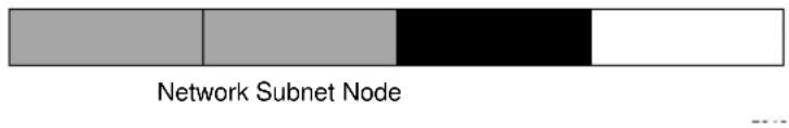
text_image
Network Subnet NodeFigure B-2: Example of Subnetting a Class B Address
A Class B address can be effectively translated into multiple Class C addresses. For example, the IP address of 172.16.0.0 is assigned, but node addresses are limited to 255 maximum, allowing eight extra bits to use as a subnet address. The IP address of 172.16.97.235 would be interpreted as IP network address 172.16, subnet number 97, and node number 235. In addition to extending the number of addresses available, subnet addressing provides other benefits. Subnet addressing allows a network manager to construct an address scheme for the network by using different subnets for other geographical locations in the network or for other departments in the organization.
Although the preceding example uses the entire third octet for a subnet address, note that you are not restricted to octet boundaries in subnetting. To create more network numbers, you need only shift some bits from the host address to the network address. For instance, to partition a Class C network number (192.68.135.0) into two, you shift one bit from the host address to the network address. The new netmask (or subnet mask) is 255.255.255.128. The first subnet has network number 192.68.135.0 with hosts 192.68.135.1 to 129.68.135.126, and the second subnet has network number 192.68.135.128 with hosts 192.68.135.129 to 192.68.135.254.

Note: The number 192.68.135.127 is not assigned because it is the broadcast address of the first subnet. The number 192.68.135.128 is not assigned because it is the network address of the second subnet.
The following table lists the additional subnet mask bits in dotted-decimal notation. To use the table, write down the original class netmask and replace the 0 value octets with the dotted-decimal value of the additional subnet bits. For example, to partition your Class C network with subnet mask 255.255.255.0 into 16 subnets (4 bits), the new subnet mask becomes 255.255.255.240.
Table B-1. Netmask Notation Translation Table for One Octet
| Number of Bits Dotted-Decimal Value |
| 1 128 |
| 2 192 |
| 3 224 |
| 4 240 |
| 5 248 |
| 6 252 |
| 7 254 |
| 8 255 |
The following table displays several common netmask values in both the dotted-decimal and the masklength formats.
Table B-2. Netmask Formats
| Dotted-Decimal Masklength |
| 255.0.0.0 /8 |
| 255.255.0.0 /16 |
| 255.255.255.0 /24 |
| 255.255.255.128 /25 |
| 255.255.255.192 /26 |
| 255.255.255.224 /27 |
| 255.255.255.240 /28 |
| 255.255.255.248 /29 |
Table B-2. Netmask Formats
| 255.255.255.252 /30 |
| 255.255.255.254 /31 |
| 255.255.255.255 /32 |
Configure all hosts on a LAN segment to use the same netmask for the following reasons:
- So that hosts recognize local IP broadcast packets
When a device broadcasts to its segment neighbors, it uses a destination address of the local network address with all ones for the host address. In order for this scheme to work, all devices on the segment must agree on which bits comprise the host address.
• So that a local router or bridge recognizes which addresses are local and which are remote
Private IP Addresses
If your local network is isolated from the Internet (for example, when using NAT), you can assign any IP addresses to the hosts without problems. However, the IANA has reserved the following three blocks of IP addresses specifically for private networks:
10.0.0.0 - 10.255.255.255
172.16.0.0 - 172.31.255.255
192.168.0.0 - 192.168.255.255
Choose your private network number from this range. The DHCP server of the Wireless Range Extender Kit is preconfigured to automatically assign private addresses.
Regardless of your particular situation, do not create an arbitrary IP address; always follow the guidelines explained here. For more information about address assignment, refer to RFC 1597, Address Allocation for Private Internets, and RFC 1466, Guidelines for Management of IP Address Space. The Internet Engineering Task Force (IETF) publishes RFCs on its Web site at http://www.ietf.org.
Single IP Address Operation Using NAT
In the past, if multiple computers on a LAN needed to access the Internet simultaneously, you had to obtain a range of IP addresses from the ISP. This type of Internet account is more costly than a single-address account typically used by a single user with a modem, rather than a router. The Wireless Range Extender Kit employs an address-sharing method called Network Address Translation (NAT). This method allows several networked computers to share an Internet account using only a single IP address, which may be statically or dynamically assigned by your ISP.
The router accomplishes this address sharing by translating the internal LAN IP addresses to a single address that is globally unique on the Internet. The internal LAN IP addresses can be either private addresses or registered addresses. For more information about IP address translation, refer to RFC 1631, The IP Network Address Translator (NAT).
The following figure illustrates a single IP address operation.

flowchart
graph TD
    A["192.168.0.2"] --> B["192.168.0.1 172.21.15.105"]
    C["192.168.0.3"] --> B
    D["192.168.0.4"] --> B
    E["192.168.0.5"] --> B
    B --> F["Internet"]
    G["Private IP addresses assigned by user"] --> A
    H["IP addresses assigned by ISP"] --> B
Figure B-3: Single IP Address Operation Using NAT
This scheme offers the additional benefit of firewall-like protection because the internal LAN addresses are not available to the Internet through the translated connection. All incoming inquiries are filtered out by the router. This filtering can prevent intruders from probing your system. However, using port forwarding, you can allow one computer (for example, a Web server) on your local network to be accessible to outside users.
MAC Addresses and Address Resolution Protocol
An IP address alone cannot be used to deliver data from one LAN device to another. To send data between LAN devices, you must convert the IP address of the destination device to its media access control (MAC) address. Each device on an Ethernet network has a unique MAC address, which is a 48-bit number assigned to each device by the manufacturer. The technique that associates the IP address with a MAC address is known as address resolution. Internet Protocol uses the Address Resolution Protocol (ARP) to resolve MAC addresses.
If a device sends data to another station on the network and the destination MAC address is not yet recorded, ARP is used. An ARP request is broadcast onto the network. All stations on the network receive and read the request. The destination IP address for the chosen station is included as part of the message so that only the station with this IP address responds to the ARP request. All other stations discard the request.
Related Documents
The station with the correct IP address responds with its own MAC address directly to the sending device. The receiving station provides the transmitting station with the required destination MAC address. The IP address data and MAC address data for each station are held in an ARP table. The next time data is sent, the address can be obtained from the address information in the table.
For more information about address assignment, refer to the IETF documents RFC 1597, Address Allocation for Private Internets, and RFC 1466, Guidelines for Management of IP Address Space.
For more information about IP address translation, refer to RFC 1631, The IP Network Address Translator (NAT).
Domain Name Server
Many of the resources on the Internet can be addressed by simple descriptive names such as http://www.NETGEAR.com. This addressing is very helpful at the application level, but the descriptive name must be translated to an IP address in order for a user to actually contact the resource. Just as a telephone directory maps names to phone numbers, or as an ARP table maps IP addresses to MAC addresses, a domain name system (DNS) server maps descriptive names of network resources to IP addresses.
When a computer accesses a resource by its descriptive name, it first contacts a DNS server to obtain the IP address of the resource. The computer sends the desired message using the IP address. Many large organizations, such as ISPs, maintain their own DNS servers and allow their customers to use the servers to look up addresses.
IP Configuration by DHCP
When an IP-based local area network is installed, each computer must be configured with an IP address. If the computers need to access the Internet, they should also be configured with a gateway address and one or more DNS server addresses. As an alternative to manual configuration, there is a method by which each computer on the network can automatically obtain this configuration information. A device on the network may act as a Dynamic Host Configuration Protocol (DHCP) server. The DHCP server stores a list or pool of IP addresses, along with other information (such as gateway and DNS addresses) that it may assign to the other devices on the network. The Wireless Range Extender Kit has the capacity to act as a DHCP server.
The Wireless Range Extender Kit also functions as a DHCP client when connecting to the ISP. The router can automatically obtain an IP address, subnet mask, DNS server addresses, and a gateway address if the ISP provides this information by DHCP.
Internet Security and Firewalls
When your LAN connects to the Internet through a router, an opportunity is created for outsiders to access or disrupt your network. A NAT router provides some protection because by the very nature of the process, the network behind the router is shielded from access by outsiders on the Internet. However, there are methods by which a determined hacker can possibly obtain information about your network or at the least can disrupt your Internet access. A greater degree of protection is provided by a firewall router.
What is a Firewall?
A firewall is a device that protects one network from another, while allowing communication between the two. A firewall incorporates the functions of the NAT router, while adding features for dealing with a hacker intrusion or attack. Several known types of intrusion or attack can be recognized when they occur. When an incident is detected, the firewall can log details of the attempt, and can optionally send E-mail to an administrator notifying them of the incident. Using information from the log, the administrator can take action with the ISP of the hacker. In some types of intrusions, the firewall can fend off the hacker by discarding all further packets from the hacker's IP address for a period of time.
Stateful Packet Inspection
Unlike simple Internet sharing routers, a firewall uses a process called stateful packet inspection to ensure secure firewall filtering to protect your network from attacks and intrusions. Since user-level applications such as FTP and Web browsers can create complex patterns of network traffic, it is necessary for the firewall to analyze groups of network connection states. Using Stateful Packet Inspection, an incoming packet is intercepted at the network layer and then analyzed for state-related information associated with all network connections. A central cache within the firewall keeps track of the state information associated with all network connections. All traffic passing through the firewall is analyzed against the state of these connections in order to determine whether or not it will be allowed to pass through or rejected.
Denial of Service Attack
A hacker may be able to prevent your network from operating or communicating by launching a Denial of Service (DoS) attack. The method used for such an attack can be as simple as merely flooding your site with more requests than it can handle. A more sophisticated attack may attempt to exploit some weakness in the operating system used by your router or gateway. Some operating systems can be disrupted by simply sending a packet with incorrect length information.
Ethernet Cabling
Although Ethernet networks originally used thick or thin coaxial cable, most installations currently use unshielded twisted pair (UTP) cabling. The UTP cable contains eight conductors, arranged in four twisted pairs, and terminated with an RJ45 type connector. A normal straight-through UTP Ethernet cable follows the EIA568B standard wiring as described below in Table 3.
Table B-3. UTP Ethernet cable wiring, straight-through
| Pin Wire Color Signal | ||
| 1 Orange/White Transmit (Tx) + | ||
| 2 Orange Transmit (Tx) - | ||
| 3 Green/White Receive (Rx) + | ||
| 4 | B I u e | |
| 5 Blue/White | ||
| 6 Green Receive (Rx) - | ||
| 7 Brown/White | ||
| 8 | B r o w n | |
Category 5 Cable Quality
Category 5 distributed cable that meets ANSI/EIA/TIA-568-A building wiring standards can be a maximum of 328 feet (ft.) or 100 meters (m) in length, divided as follows:
20 ft. (6 m) between the hub and the patch panel (if used)
295 ft. (90 m) from the wiring closet to the wall outlet
10 ft. (3 m) from the wall outlet to the desktop device
The patch panel and other connecting hardware must meet the requirements for 100 Mbps operation (Category 5). Only 0.5 inch (1.5 cm) of untwist in the wire pair is allowed at any termination point.
A twisted pair Ethernet network operating at 10 Mbits/second (10BASE-T) will often tolerate low quality cables, but at 100 Mbits/second (10BASE-Tx) the cable must be rated as Category 5, or Cat 5, by the Electronic Industry Association (EIA). This rating will be printed on the cable jacket. A Category 5 cable will meet specified requirements regarding loss and crosstalk. In addition, there are restrictions on maximum cable length for both 10 and 100 Mbits/second networks.
Inside Twisted Pair Cables
For two devices to communicate, the transmitter of each device must be connected to the receiver of the other device. The crossover function is usually implemented internally as part of the circuitry in the device. Computers and workstation adapter cards are usually media-dependent interface ports, called MDI or uplink ports. Most repeaters and switch ports are configured as media-dependent interfaces with built-in crossover ports, called MDI-X or normal ports. Auto Uplink technology automatically senses which connection, MDI or MDI-X, is needed and makes the right connection.
Figure B-4 illustrates straight-through twisted pair cable.
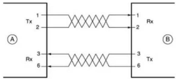
text_image
Tx 1 2 Rx 3 6 1 Rx 2 3 Tx 6 A BKey:
A = UPLINK OR MDI PORT (as on a PC)
B = Normal or MDI-X port (as on a hub or switch)
1, 2, 3, 6 = Pin numbers
Figure B-4: Straight-Through Twisted-Pair Cable
Figure B-5 illustrates crossover twisted pair cable.
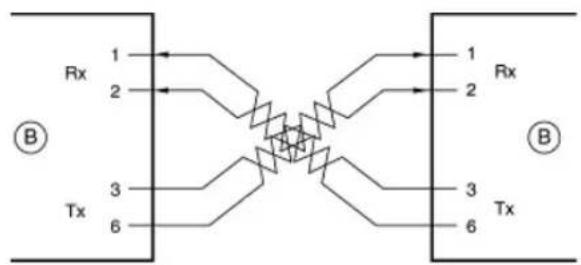
flowchart
graph TD
    A["Terminal 1"] --> B["Switch"]
    C["Terminal 2"] --> B
    D["Terminal 3"] --> E["Switch"]
    F["Terminal 4"] --> E
    G["Terminal 5"] --> E
    H["Terminal 6"] --> E
    I["Rx 1"] --> J["Switch"]
    K["Tx 2"] --> J
    L["Tx 3"] --> M["Switch"]
    N["Tx 4"] --> M
    O["Tx 5"] --> M
    P["Tx 6"] --> M
    Q["B"] --> R["Terminal 1"]
    S["B"] --> T["Terminal 2"]
    U["B"] --> V["Terminal 3"]
    W["B"] --> X["Terminal 4"]
    Y["B"] --> Z["Terminal 5"]
Key:
B = Normal or MDI-X port (as on a hub or switch)
1, 2, 3, 6 = Pin numbers
Figure B-5: Crossover Twisted-Pair Cable

text_image
1 = RJ-45 plug 2 = Category 5 UTP patch cableFigure B-6: Category 5 UTP Cable with Male RJ-45 Plug at Each End
Note: Flat “silver satin” telephone cable may have the same RJ-45 plug. However, using telephone cable results in excessive collisions, causing the attached port to be partitioned or disconnected from the network.
Uplink Switches, Crossover Cables, and MDI/MDIX Switching
In the wiring table above, the concept of transmit and receive are from the perspective of the computer, which is wired as Media Dependant Interface (MDI). In this wiring, the computer transmits on pins 1 and 2. At the hub, the perspective is reversed, and the hub receives on pins 1 and 2. This wiring is referred to as Media Dependant Interface - Crossover (MDI-X).
When connecting a computer to a computer, or a hub port to another hub port, the transmit pair must be exchanged with the receive pair. This exchange is done by one of two mechanisms. Most hubs provide an Uplink switch which will exchange the pairs on one port, allowing that port to be connected to another hub using a normal Ethernet cable. The second method is to use a crossover cable, which is a special cable in which the transmit and receive pairs are exchanged at one of the two cable connectors. Crossover cables are often unmarked as such, and must be identified by comparing the two connectors. Since the cable connectors are clear plastic, it is easy to place them side by side and view the order of the wire colors on each. On a straight-through cable, the color order will be the same on both connectors. On a crossover cable, the orange and green pairs will be exchanged from one connector to the other.
Most routers incorporates Auto Uplink ^™ technology (also called MDI/MDIX). Each LOCAL Ethernet port will automatically sense whether the Ethernet cable plugged into the port should have a normal connection (e.g. connecting to a computer) or an uplink connection (e.g. connecting to a router, switch, or hub). That port will then configure itself to the correct configuration. This feature also eliminates the need to worry about crossover cables, as Auto Uplink ^™ will accommodate either type of cable to make the right connection.
Appendix C
Wireless Networking Basics
This chapter provides an overview of Wireless networking.
Wireless Networking Overview
The Wireless Range Extender Kit conforms to the Institute of Electrical and Electronics Engineers (IEEE) 802.11 standard for wireless LANs (WLANs) and a product update will bring the WGB102 into conformance to the 802.11g standard when it is ratified. On an 802.11b or g wireless link, data is encoded using direct-sequence spread-spectrum (DSSS) technology and is transmitted in the unlicensed radio spectrum at 2.5GHz. The maximum data rate for the wireless link is 11 Mbps, but it will automatically back down from 11 Mbps to 5.5, 2, and 1 Mbps when the radio signal is weak or when interference is detected. The 802.11g auto rate sensing rates are 1, 2, 5.5, 6, 9, 12, 18, 24, 36, 48, and 54 Mbps.
The 802.11 standard is also called Wireless Ethernet or Wi-Fi by the Wireless Ethernet Compatibility Alliance (WECA, see http://www.wi-fi.net), an industry standard group promoting interoperability among 802.11 devices. The 802.11 standard offers two methods for configuring a wireless network — ad hoc and infrastructure.
Infrastructure Mode
With a wireless Access Point, you can operate the wireless LAN in the infrastructure mode. This mode provides wireless connectivity to multiple wireless network devices within a fixed range or area of coverage, interacting with wireless nodes via an antenna.
In the infrastructure mode, the wireless access point converts airwave data into wired Ethernet data, acting as a bridge between the wired LAN and wireless clients. Connecting multiple Access Points via a wired Ethernet backbone can further extend the wireless network coverage. As a mobile computing device moves out of the range of one access point, it moves into the range of another. As a result, wireless clients can freely roam from one Access Point domain to another and still maintain seamless network connection.
Ad Hoc Mode (Peer-to-Peer Workgroup)
In an ad hoc network, computers are brought together as needed; thus, there is no structure or fixed points to the network — each node can generally communicate with any other node. There is no Access Point involved in this configuration. This mode enables you to quickly set up a small wireless workgroup and allows workgroup members to exchange data or share printers as supported by Microsoft networking in the various Windows operating systems. Some vendors also refer to ad hoc networking as peer-to-peer group networking.
In this configuration, network packets are directly sent and received by the intended transmitting and receiving stations. As long as the stations are within range of one another, this is the easiest and least expensive way to set up a wireless network.
Network Name: Extended Service Set Identification (ESSID)
The Extended Service Set Identification (ESSID) is one of two types of Service Set Identification (SSID). In an ad hoc wireless network with no access points, the Basic Service Set Identification (BSSID) is used. In an infrastructure wireless network that includes an access point, the ESSID is used, but may still be referred to as SSID.
An SSID is a thirty-two character (maximum) alphanumeric key identifying the name of the wireless local area network. Some vendors refer to the SSID as network name. For the wireless devices in a network to communicate with each other, all devices must be configured with the same SSID.
Authentication and WEP
The absence of a physical connection between nodes makes the wireless links vulnerable to eavesdropping and information theft. To provide a certain level of security, the IEEE 802.11 standard has defined two types of authentication methods, Open System and Shared Key. With Open System authentication, a wireless PC can join any network and receive any messages that are not encrypted. With Shared Key authentication, only those PCs that possess the correct authentication key can join the network. By default, IEEE 802.11 wireless devices operate in an Open System network.
Wired Equivalent Privacy (WEP) data encryption is used when the wireless devices are configured to operate in Shared Key authentication mode. There are two shared key methods implemented in most commercially available products, 64-bit and 128-bit WEP data encryption.
802.11 Authentication
The 802.11 standard defines several services that govern how two 802.11 devices communicate. The following events must occur before an 802.11 Station can communicate with an Ethernet network through an access point such as the one built in to the WGB102:
- Turn on the wireless station.
- The station listens for messages from any access points that are in range.
- The station finds a message from an access point that has a matching SSID.
- The station sends an authentication request to the access point.
- The access point authenticates the station.
- The station sends an association request to the access point.
- The access point associates with the station.
- The station can now communicate with the Ethernet network through the access point.
An access point must authenticate a station before the station can associate with the access point or communicate with the network. The IEEE 802.11 standard defines two types of authentication: Open System and Shared Key.
- Open System Authentication allows any device to join the network, assuming that the device SSID matches the access point SSID. Alternatively, the device can use the “ANY” SSID option to associate with any available Access Point within range, regardless of its SSID.
- Shared Key Authentication requires that the station and the access point have the same WEP Key to authenticate. These two authentication procedures are described below.
Open System Authentication
The following steps occur when two devices use Open System Authentication:
- The station sends an authentication request to the access point.
- The access point authenticates the station.
- The station associates with the access point and joins the network.
This process is illustrated in below.
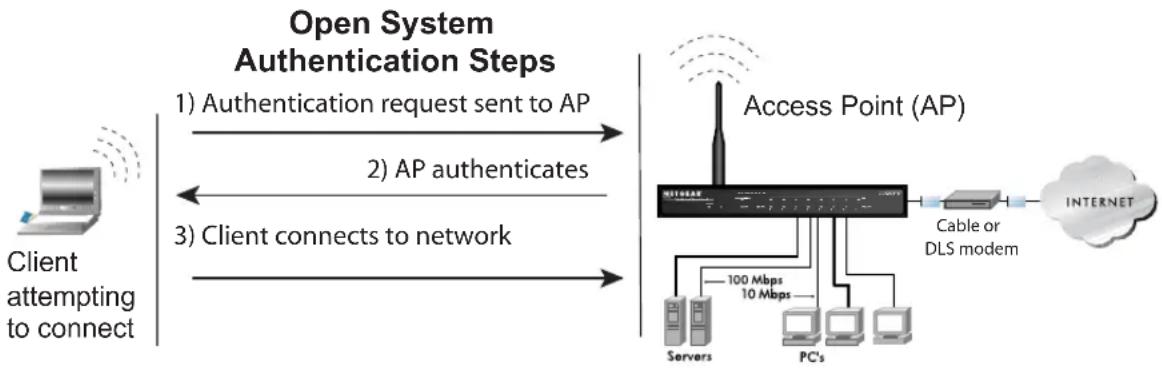
flowchart
graph LR
    A["Client attempting to connect"] -->|1) Authentication request sent to AP| B["Access Point (AP)"]
    B -->|2) AP authenticates| C["Cable or DLS modem"]
    B -->|3) Client connects to network| D["Internet"]
    B --> E["5Gbps 100 Mbps"]
    B --> F["5Gbps 10 Mbps"]
    E --> G["Servers"]
    E --> H["PC's"]
Figure 8-4: Open system authentication
Shared Key Authentication
The following steps occur when two devices use Shared Key Authentication:
- The station sends an authentication request to the access point.
- The access point sends challenge text to the station.
- The station uses its configured 64-bit or 128-bit default key to encrypt the challenge text, and sends the encrypted text to the access point.
- The access point decrypts the encrypted text using its configured WEP Key that corresponds to the station's default key. The access point compares the decrypted text with the original challenge text. If the decrypted text matches the original challenge text, then the access point and the station share the same WEP Key and the access point authenticates the station.
5. The station connects to the network.
If the decrypted text does not match the original challenge text (i.e., the access point and station do not share the same WEP Key), then the access point will refuse to authenticate the station and the station will be unable to communicate with either the 802.11 network or Ethernet network.
This process is illustrated in below.
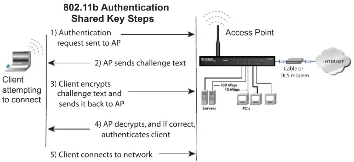
flowchart
graph LR
    A["Client attempting to connect"] --> B["1) Authentication request sent to AP"]
    B --> C["2) AP sends challenge text"]
    C --> D["3) Client encrypts challenge text and sends it back to AP"]
    D --> E["4) AP decrypts, and if correct, authenticates client"]
    E --> F["5) Client connects to network"]
    F --> G["Access Point"]
    G --> H["Cable or DLS modem"]
    H --> I["INTERNET"]
    G --> J["Servers"]
    G --> K["PC's"]
    G --> L["100 Mbps 10 Mbps"]
Figure 8-5: Shared key authentication
Overview of WEP Parameters
Before enabling WEP on an 802.11 network, you must first consider what type of encryption you require and the key size you want to use. Typically, there are three WEP Encryption options available for 802.11 products:
- Do Not Use WEP: The 802.11 network does not encrypt data. For authentication purposes, the network uses Open System Authentication.
-
Use WEP for Encryption: A transmitting 802.11 device encrypts the data portion of every packet it sends using a configured WEP Key. The receiving device decrypts the data using the same WEP Key. For authentication purposes, the wireless network uses Open System Authentication.
-
Use WEP for Authentication and Encryption: A transmitting 802.11 device encrypts the data portion of every packet it sends using a configured WEP Key. The receiving 802.11 device decrypts the data using the same WEP Key. For authentication purposes, the 802.11 network uses Shared Key Authentication.
Note: Some 802.11 access points also support Use WEP for Authentication Only (Shared Key Authentication without data encryption).
Key Size
The IEEE 802.11 standard supports two types of WEP encryption: 40-bit and 128-bit.
The 64-bit WEP data encryption method, allows for a five-character (40-bit) input. Additionally, 24 factory-set bits are added to the forty-bit input to generate a 64-bit encryption key. (The 24 factory-set bits are not user-configurable). This encryption key will be used to encrypt/decrypt all data transmitted via the wireless interface. Some vendors refer to the 64-bit WEP data encryption as 40-bit WEP data encryption since the user-configurable portion of the encryption key is 40 bits wide.
The 128-bit WEP data encryption method consists of 104 user-configurable bits. Similar to the forty-bit WEP data encryption method, the remaining 24 bits are factory set and not user configurable. Some vendors allow passphrases to be entered instead of the cryptic hexadecimal characters to ease encryption key entry.
128-bit encryption is stronger than 40-bit encryption, but 128-bit encryption may not be available outside of the United States due to U.S. export regulations.
When configured for 40-bit encryption, 802.11 products typically support up to four WEP Keys. Each 40-bit WEP Key is expressed as 5 sets of two hexadecimal digits (0-9 and A-F). For example, “12 34 56 78 90” is a 40-bit WEP Key.
When configured for 128-bit encryption, wireless products typically support four WEP Keys but some manufacturers support only one 128-bit key. The 128-bit WEP Key is expressed as 13 sets of two hexadecimal digits (0-9 and A-F). For example, “12 34 56 78 90 AB CD EF 12 34 56 78 90” is a 128-bit WEP Key.
Note: Typically, 802.11 access points can store up to four 128-bit WEP Keys but some 802.11 client adapters can only store one. Therefore, make sure that your 802.11 access and client adapters configurations match.
WEP Configuration Options
The WEP settings must match on all 802.11 devices that are within the same wireless network as identified by the SSID. In general, if your mobile clients will roam between access points, then all of the 802.11 access points and all of the 802.11 client adapters on the network must have the same WEP settings.
Note: Whatever keys you enter for an AP, you must also enter the same keys for the client adapter in the same order. In other words, WEP key 1 on the AP must match WEP key 1 on the client adapter, WEP key 2 on the AP must match WEP key 2 on the client adapter, etc.
Note: The AP and the client adapters can have different default WEP Keys as long as the keys are in the same order. In other words, the AP can use WEP key 2 as its default key to transmit while a client adapter can use WEP key 3 as its default key to transmit. The two devices will communicate as long as the AP's WEP key 2 is the same as the client's WEP key 2 and the AP's WEP key 3 is the same as the client's WEP key 3.
Wireless Channels
IEEE 802.11 wireless nodes communicate with each other using radio frequency signals in the ISM (Industrial, Scientific, and Medical) band between 2.4 GHz and 2.5 GHz. Neighboring channels are 5 MHz apart. However, due to spread spectrum effect of the signals, a node sending signals using a particular channel will utilize frequency spectrum 12.5 MHz above and below the center channel frequency. As a result, two separate wireless networks using neighboring channels (for example, channel 1 and channel 2) in the same general vicinity will interfere with each other. Applying two channels that allow the maximum channel separation will decrease the amount of channel crosstalk, and provide a noticeable performance increase over networks with minimal channel separation.
The radio frequency channels used are listed in Table 8-1:
Table 8-1. 802.11 Radio Frequency Channels
| Channel Center Frequency Frequency Spread | |
| 1 2412 MHz 2 | 399.5 MHz - 2424.5 MHz |
| 2 2417 MHz 2 | 404.5 MHz - 2429.5 MHz |
| 3 2422 MHz 2 | 409.5 MHz - 2434.5 MHz |
| 4 2427 MHz 2 | 414.5 MHz - 2439.5 MHz |
| 5 2432 MHz 2 | 419.5 MHz - 2444.5 MHz |
| 6 2437 MHz 2 | 424.5 MHz - 2449.5 MHz |
| 7 2442 MHz 2 | 429.5 MHz - 2454.5 MHz |
| 8 2447 MHz 2 | 434.5 MHz - 2459.5 MHz |
| 9 2452 MHz 2 | 439.5 MHz - 2464.5 MHz |
| 10 2457 MHz | 2444.5 MHz - 2469.5 MHz |
| 11 2462 MHz | 2449.5 MHz - 2474.5 MHz |
| 12 2467 MHz | 2454.5 MHz - 2479.5 MHz |
| 13 2472 MHz | 2459.5 MHz - 2484.5 MHz |
Note: The available channels supported by the wireless products in various countries are different.
The preferred channel separation between the channels in neighboring wireless networks is 25 MHz (5 channels). This means that you can apply up to three different channels within your wireless network. There are only 11 usable wireless channels in the United States. It is recommended that you start using channel 1 and grow to use channel 6, and 11 when necessary, as these three channels do not overlap.
WPA Wireless Security
Wi-Fi Protected Access (WPA) is a specification of standards-based, interoperable security enhancements that increase the level of data protection and access control for existing and future wireless LAN systems.
The IEEE introduced the WEP as an optional security measure to secure 802.11b (Wi-Fi) WLANs, but inherent weaknesses in the standard soon became obvious. In response to this situation, the Wi-Fi Alliance announced a new security architecture in October 2002 that remedies the shortcomings of WEP. This standard, formerly known as Safe Secure Network (SSN), is designed to work with existing 802.11 products and offers forward compatibility with 802.11i, the new wireless security architecture being defined in the IEEE.
WPA offers the following benefits:
• Enhanced data privacy
- Robust key management
• Data origin authentication
• Data integrity protection
How Does WPA Compare to WEP?
WEP is a data encryption method and is not intended as a user authentication mechanism. WPA user authentication is implemented using 802.1x and the Extensible Authentication Protocol (EAP). Support for 802.1x authentication is required in WPA. In the 802.11 standard, 802.1x authentication was optional. For details on EAP specifically, refer to IETF's RFC 2284.
With 802.11 WEP, all access points and client wireless adapters on a particular wireless LAN must use the same encryption key. A major problem with the 802.11 standard is that the keys are cumbersome to change. If you do not update the WEP keys often, an unauthorized person with a sniffing tool can monitor your network for less than a day and decode the encrypted messages. Products based on the 802.11 standard alone offer system administrators no effective method to update the keys.
For 802.11, WEP encryption is optional. For WPA, encryption using Temporal Key Integrity Protocol (TKIP) is required. TKIP replaces WEP with a new encryption algorithm that is stronger than the WEP algorithm, but that uses the calculation facilities present on existing wireless devices to perform encryption operations. TKIP provides important data encryption enhancements including a per-packet key mixing function, a message integrity check (MIC) named Michael, an extended initialization vector (IV) with sequencing rules, and a re-keying mechanism. Through these enhancements, TKIP addresses all of known WEP vulnerabilities.
How Does WPA Compare to IEEE 802.11i?
WPA will be forward compatible with the IEEE 802.11i security specification currently under development. WPA is a subset of the current 802.11i draft and uses certain pieces of the 802.11i draft that are ready to bring to market today, such as 802.1x and TKIP. The main pieces of the 802.11i draft that are not included in WPA are secure IBSS (Ad-Hoc mode), secure fast handoff (for specialized 802.11 VoIP phones), as well as enhanced encryption protocols, such as AES-CCMP. These features are either not yet ready for market or will require hardware upgrades to implement.
What are the Key Features of WPA Security?
The following security features are included in the WPA standard:
- WPA Authentication
• WPA Encryption Key Management
– Temporal Key Integrity Protocol (TKIP)
– Michael message integrity code (MIC)
– AES Support (to be phased in)
- Support for a Mixture of WPA and WEP Wireless Clients, but mixing WEP and WPA is discouraged
These features are discussed below.
WPA addresses most of the known WEP vulnerabilities and is primarily intended for wireless infrastructure networks as found in the enterprise. This infrastructure includes stations, access points, and authentication servers (typically RADIUS servers). The RADIUS server holds (or has access to) user credentials (for example, user names and passwords) and authenticates wireless users before they gain access to the network.
The strength of WPA comes from an integrated sequence of operations that encompass 802.1X/EAP authentication and sophisticated key management and encryption techniques. Its major operations include:
- Network security capability determination. This occurs at the 802.11 level and is communicated through WPA information elements in Beacon, Probe Response, and (Re) Association Requests. Information in these elements includes the authentication method (802.1X or Pre-shared key) and the preferred cipher suite (WEP, TKIP, or AES).
The primary information conveyed in the Beacon frames is the authentication method and the cipher suite. Possible authentication methods include 802.1X and Pre-shared key. Pre-shared key is an authentication method that uses a statically configured pass phrase on both the stations and the access point. This obviates the need for an authentication server, which in many home and small office environments will not be available nor desirable. Possible cipher suites include: WEP, TKIP, and AES (Advanced Encryption Standard). We talk more about TKIP and AES when addressing data privacy below.
- Authentication. EAP over 802.1X is used for authentication. Mutual authentication is gained by choosing an EAP type supporting this feature and is required by WPA. 802.1X port access control prevents full access to the network until authentication completes. 802.1X EAPOL-Key packets are used by WPA to distribute per-session keys to those stations successfully authenticated.
The supplicant in the station uses the authentication and cipher suite information contained in the information elements to decide which authentication method and cipher suite to use. For example, if the access point is using the pre-shared key method then the supplicant need not authenticate using full-blown 802.1X. Rather, the supplicant must simply prove to the access point that it is in possession of the pre-shared key. If the supplicant detects that the service set does not contain a WPA information element then it knows it must use pre-WPA 802.1X authentication and key management in order to access the network.
- Key management. WPA features a robust key generation/management system that integrates the authentication and data privacy functions. Keys are generated after successful authentication and through a subsequent 4-way handshake between the station and Access Point (AP).
- Data Privacy (Encryption). Temporal Key Integrity Protocol (TKIP) is used to wrap WEP in sophisticated cryptographic and security techniques to overcome most of its weaknesses.
- Data integrity. TKIP includes a message integrity code (MIC) at the end of each plaintext message to ensure messages are not being spoofed.
WPA Authentication: Enterprise-level User Authentication via 802.1x/EAP and RADIUS
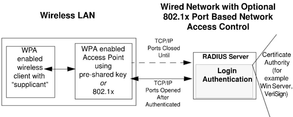
flowchart
graph LR
    A["WPA enabled wireless client with "supplicant""] --> B["WPA enabled Access Point using pre-shared key or 802.1x"]
    B --> C["RADIUS Server Login Authentication"]
    D["TCP/IP Ports Closed Until"] -.-> C
    E["TCP/IP Ports Opened After Authenticated"] --> C
    F["Certificate Authority (for example Win Server, VeriSign)"] --> C
Figure C-1: WPA Overview
IEEE 802.1x offers an effective framework for authenticating and controlling user traffic to a protected network, as well as providing a vehicle for dynamically varying data encryption keys via EAP from a RADIUS server, for example. This framework enables using a central authentication server, which employs mutual authentication so that a rogue wireless user does not join the network.
It is important to note that 802.1x does not provide the actual authentication mechanisms. When using 802.1x, the EAP type, such as Transport Layer Security (EAP-TLS), or EAP Tunneled Transport Layer Security (EAP-TTLS), defines how the authentication takes place.
Note: For environments with a Remote Authentication Dial-In User Service (RADIUS) infrastructure, WPA supports Extensible Authentication Protocol (EAP). For environments without a RADIUS infrastructure, WPA supports the use of a pre-shared key.
Together, these technologies provide a framework for strong user authentication.
Windows XP implements 802.1x natively, and several NETGEAR switch and wireless access point products support 802.1x.
Client with a WPA-enabled wireless adapter and supplicant (Win XP, Funk, Meetinghouse)
For example, a WPA-enabled AP
For example, a RADIUS server
flowchart
graph TD
    A["Supplicant"] -->|1| B["Authenticator"]
    B -->|2 Challenge| C["Antenna Server"]
    C -->|3 Request Credentials| B
    B -->|4 Request Credentials| C
    C -->|5 Authentication Key| D["Controlled Port"]
    D -->|6 Authentication Key| C
    C -->|7 LAN Resources| E["Controlled Port"]
    style A fill:#f9f,stroke:#333
    style B fill:#ccf,stroke:#333
    style C fill:#cfc,stroke:#333
    style D fill:#fcc,stroke:#333
    style E fill:#cff,stroke:#333
Figure C-2: 802.1x Authentication Sequence
The AP sends Beacon Frames with WPA information element to the stations in the service set. Information elements include the required authentication method (802.1x or Pre-shared key) and the preferred cipher suite (WEP, TKIP, or AES). Probe Responses (AP to station) and Association Requests (station to AP) also contain WPA information elements.
- Initial 802.1x communications begin with an unauthenticated supplicant (client device) attempting to connect with an authenticator (802.11 access point). The client sends an EAP-start message. This begins a series of message exchanges to authenticate the client.
-
The access point replies with an EAP-request identity message.
-
The client sends an EAP-response packet containing the identity to the authentication server. The access point responds by enabling a port for passing only EAP packets from the client to an authentication server located on the wired side of the access point. The access point blocks all other traffic, such as HTTP, DHCP, and POP3 packets, until the access point can verify the client's identity using an authentication server (for example, RADIUS).
- The authentication server uses a specific authentication algorithm to verify the client's identity. This could be through the use of digital certificates or some other EAP authentication type.
- The authentication server will either send an accept or reject message to the access point.
- The access point sends an EAP-success packet (or reject packet) to the client.
- If the authentication server accepts the client, then the access point will transition the client's port to an authorized state and forward additional traffic.
The important part to know at this point is that the software supporting the specific EAP type resides on the authentication server and within the operating system or application “supplicant” software on the client devices. The access point acts as a “pass through” for 802.1x messages, which means that you can specify any EAP type without needing to upgrade an 802.1x-compliant access point. As a result, you can update the EAP authentication type to such devices as token cards (Smart Cards), Kerberos, one-time passwords, certificates, and public key authentication, or as newer types become available and your requirements for security change.
WPA Data Encryption Key Management
With 802.1x, the rekeying of unicast encryption keys is optional. Additionally, 802.11 and 802.1x provide no mechanism to change the global encryption key used for multicast and broadcast traffic. With WPA, rekeying of both unicast and global encryption keys is required.
For the unicast encryption key, the Temporal Key Integrity Protocol (TKIP) changes the key for every frame, and the change is synchronized between the wireless client and the wireless access point (AP). For the global encryption key, WPA includes a facility (the Information Element) for the wireless AP to advertise the changed key to the connected wireless clients.
If configured to implement dynamic key exchange, the 802.1x authentication server can return session keys to the access point along with the accept message. The access point uses the session keys to build, sign and encrypt an EAP key message that is sent to the client immediately after sending the success message. The client can then use contents of the key message to define applicable encryption keys. In typical 802.1x implementations, the client can automatically change encryption keys as often as necessary to minimize the possibility of eavesdroppers having enough time to crack the key in current use.
Temporal Key Integrity Protocol (TKIP)
WPA uses TKIP to provide important data encryption enhancements including a per-packet key mixing function, a message integrity check (MIC) named Michael, an extended initialization vector (IV) with sequencing rules, and a re-keying mechanism. TKIP also provides for the following:
- The verification of the security configuration after the encryption keys are determined.
- The synchronized changing of the unicast encryption key for each frame.
- The determination of a unique starting unicast encryption key for each preshared key authentication.
Michael
With 802.11 and WEP, data integrity is provided by a 32-bit integrity check value (ICV) that is appended to the 802.11 payload and encrypted with WEP. Although the ICV is encrypted, you can use cryptanalysis to change bits in the encrypted payload and update the encrypted ICV without being detected by the receiver.
With WPA, a method known as Michael specifies a new algorithm that calculates an 8-byte message integrity check (MIC) using the calculation facilities available on existing wireless devices. The MIC is placed between the data portion of the IEEE 802.11 frame and the 4-byte ICV. The MIC field is encrypted together with the frame data and the ICV.
Michael also provides replay protection. A new frame counter in the IEEE 802.11 frame is used to prevent replay attacks.
Optional AES Support to be Phased In
One of the encryption methods supported by WPA, besides TKIP, is the advanced encryption standard (AES), although AES support will not be required initially for Wi-Fi certification. This is viewed as the optimal choice for security conscience organizations, but the problem with AES is that it requires a fundamental redesign of the NIC's hardware in both the station and the access point. TKIP is a pragmatic compromise that allows organizations to deploy better security while AES capable equipment is being designed, manufactured, and incrementally deployed.
Is WPA Perfect?
WPA is not without its vulnerabilities. Specifically, it is susceptible to denial of service (DoS) attacks. If the access point receives two data packets that fail the message integrity code (MIC) within 60 seconds of each other, then the network is under an active attack, and as a result, the access point employs counter measures, which include disassociating each station using the access point. This prevents an attacker from gleaning information about the encryption key and alerts administrators, but it also causes users to lose network connectivity for 60 seconds. More than anything else, this may just prove that no single security tactic is completely invulnerable. WPA is a definite step forward in WLAN security over WEP and has to be thought of as a single part of an end-to-end network security strategy.
Product Support for WPA
Starting in August, 2003, NETGEAR, Inc. wireless Wi-Fi certified products will support the WPA standard. NETGEAR, Inc. wireless products that had their Wi-Fi certification approved before August, 2003 will have one year to add WPA so as to maintain their Wi-Fi certification.
WPA requires software changes to the following:
- Wireless access points
- Wireless network adapters
- Wireless client programs
Supporting a Mixture of WPA and WEP Wireless Clients is Discouraged
To support the gradual transition of WEP-based wireless networks to WPA, a wireless AP can support both WEP and WPA clients at the same time. During the association, the wireless AP determines which clients use WEP and which clients use WPA. The disadvantage to supporting a mixture of WEP and WPA clients is that the global encryption key is not dynamic. This is because WEP-based clients cannot support it. All other benefits to the WPA clients, such as integrity, are maintained.
However, a mixed mode supporting WPA and non-WPA clients would offer network security that is no better than that obtained with a non-WPA network, and thus this mode of operation is discouraged.
Changes to Wireless Access Points
Wireless access points must have their firmware updated to support the following:
• The new WPA information element
To advertise their support of WPA, wireless APs send the beacon frame with a new 802.11 WPA information element that contains the wireless AP's security configuration (encryption algorithms and wireless security configuration information).
• The WPA two-phase authentication
Open system, then 802.1x (EAP with RADIUS or preshared key).
• TKIP
• Michael
- AES (optional)
To upgrade your wireless access points to support WPA, obtain a WPA firmware update from your wireless AP vendor and upload it to your wireless AP.
Changes to Wireless Network Adapters
Wireless networking software in the adapter, and possibly in the OS or client application, must be updated to support the following:
• The new WPA information element
Wireless clients must be able to process the WPA information element and respond with a specific security configuration.
• The WPA two-phase authentication
Open system, then 802.1x supplicant (EAP or preshared key).
• TKIP
• Michael
- AES (optional)
To upgrade your wireless network adapters to support WPA, obtain a WPA update from your wireless network adapter vendor and update the wireless network adapter driver.
For Windows wireless clients, you must obtain an updated network adapter driver that supports WPA. For wireless network adapter drivers that are compatible with Windows XP (Service Pack 1) and Windows Server 2003, the updated network adapter driver must be able to pass the adapter's WPA capabilities and security configuration to the Wireless Zero Configuration service.
Microsoft has worked with many wireless vendors to embed the WPA firmware update in the wireless adapter driver. So, to update your Microsoft Windows wireless client, all you have to do is obtain the new WPA-compatible driver and install the driver. The firmware is automatically updated when the wireless network adapter driver is loaded in Windows.
Changes to Wireless Client Programs
Wireless client programs must be updated to permit the configuration of WPA authentication (and preshared key) and the new WPA encryption algorithms (TKIP and the optional AES component).
To obtain the Microsoft WPA client program, visit the Microsoft Web site.
Use the list below to find definitions for technical terms used in this manual.
List of Glossary Terms
10BASE-T
IEEE 802.3 specification for 10 Mbps Ethernet over twisted pair wiring.
100BASE-Tx
IEEE 802.3 specification for 100 Mbps Ethernet over twisted pair wiring.
802.1x
802.1x defines port-based, network access control used to provide authenticated network access and automated data encryption key management.
The IEEE 802.1x draft standard offers an effective framework for authenticating and controlling user traffic to a protected network, as well as dynamically varying encryption keys. 802.1x uses a protocol called EAP (Extensible Authentication Protocol) and supports multiple authentication methods, such as token cards, Kerberos, one-time passwords, certificates, and public key authentication. For details on EAP specifically, refer to IETF's RFC 2284.
802.11a
IEEE specification for wireless networking at 54 Mbps operating in unlicensed radio bands over 5GHz.
802.11b
IEEE specification for wireless networking at 11 Mbps using direct-sequence spread-spectrum (DSSS) technology and operating in the unlicensed radio spectrum at 2.5GHz.
802.11g
A soon to be ratified IEEE specification for wireless networking at 54 Mbps using direct-sequence spread-spectrum (DSSS) technology and operating in the unlicensed radio spectrum at 2.5GHz. 802.11g is backwards compatible with 802.11b.
ADSL
Short for asymmetric digital subscriber line, a technology that allows data to be sent over existing copper telephone lines at data rates of from 1.5 to 9 Mbps when receiving data (known as the downstream rate) and from 16 to 640 Kbps when sending data (known as the upstream rate).
ADSL requires a special ADSL modem. ADSL is growing in popularity as more areas around the world gain access.
AES
Advanced Encryption Standard, a symmetric 128-bit block data encryption technique.
It is an iterated block cipher with a variable block length and a variable key length. The block length and the key length can be independently specified to 128, 192 or 256 bits. The U.S government adopted the algorithm as its encryption technique in October 2000, replacing the DES encryption it used. AES works at multiple network layers simultaneously.
ARP
Address Resolution Protocol, a TCP/IP protocol used to convert an IP address into a physical address (called a DLC address), such as an Ethernet address.
A host wishing to obtain a physical address broadcasts an ARP request onto the TCP/IP network. The host on the network that has the IP address in the request then replies with its physical hardware address. There is also Reverse ARP (RARP) which can be used by a host to discover its IP address. In this case, the host broadcasts its physical address and a RARP server replies with the host's IP address.
Auto Uplink
Auto Uplink ^™ technology (also called MDI/MDIX) eliminates the need to worry about crossover vs. straight-through Ethernet cables. Auto Uplink ^™ will accommodate either type of cable to make the right connection.
Cat 5
Category 5 unshielded twisted pair (UTP) cabling. An Ethernet network operating at 10 Mbits/second (10BASE-T) will often tolerate low quality cables, but at 100 Mbits/second (10BASE-Tx) the cable must be rated as Category 5, or Cat 5 or Cat V, by the Electronic Industry Association (EIA).
This rating will be printed on the cable jacket. Cat 5 cable contains eight conductors, arranged in four twisted pairs, and terminated with an RJ45 type connector. In addition, there are restrictions on maximum cable length for both 10 and 100 Mbits/second networks.
Denial of Service attack
DoS. A hacker attack designed to prevent your computer or network from operating or communicating.
DHCP
An Ethernet protocol specifying how a centralized DHCP server can assign network configuration information to multiple DHCP clients. The assigned information includes IP addresses, DNS addresses, and gateway (router) addresses.
DMZ
A Demilitarized Zone is used by a company that wants to host its own Internet services without sacrificing unauthorized access to its private network.
The DMZ sits between the Internet and an internal network's line of defense, usually some combination of firewalls and bastion hosts. Typically, the DMZ contains devices accessible to Internet traffic, such as Web (HTTP) servers, FTP servers, SMTP (e-mail) servers and DNS servers.
DNS
Short for Domain Name System (or Service), an Internet service that translates domain names into IP addresses.
Because domain names are alphabetic, they're easier to remember. The Internet however, is really based on IP addresses. Every time you use a domain name, therefore, a DNS service must translate the name into the corresponding IP address. For example, the domain name www.example.com might translate to 198.105.232.4. The DNS system is, in fact, its own network. If one DNS server doesn't know how to translate a particular domain name, it asks another one, and so on, until the correct IP address is returned.
Domain Name
A descriptive name for an address or group of addresses on the Internet. Domain names are of the form of a registered entity name plus one of a number of predefined top level suffixes such as .com, .edu, .uk, etc. For example, in the address mail.NETGEAR.com, mail is a server name and NETGEAR.com is the domain.
DoS
Short for Denial of Service. A hacker attack designed to prevent your computer or network from operating or communicating.
DSL
Short for digital subscriber line, but is commonly used in reference to the asymmetric version of this technology (ADSL) that allows data to be sent over existing copper telephone lines at data rates of from 1.5 to 9 Mbps when receiving data (known as the downstream rate) and from 16 to 640 Kbps when sending data (known as the upstream rate).
ADSL requires a special ADSL modem. ADSL is growing in popularity as more areas around the world gain access.
DSLAM
DSL Access Multiplexor. The piece of equipment at the telephone company central office that provides the ADSL signal.
Dynamic Host Configuration Protocol
DHCP. An Ethernet protocol specifying how a centralized DHCP server can assign network configuration information to multiple DHCP clients. The assigned information includes IP addresses, DNS addresses, and gateway (router) addresses.
EAP
Extensible Authentication Protocol is a general protocol for authentication that supports multiple authentication methods.
EAP, an extension to PPP, supports such authentication methods as token cards, Kerberos, one-time passwords, certificates, public key authentication and smart cards. In wireless communications using EAP, a
user requests connection to a WLAN through an AP, which then requests the identity of the user and transmits that identity to an authentication server such as RADIUS. The server asks the AP for proof of identity, which the AP gets from the user and then sends back to the server to complete the authentication. EAP is defined by RFC 2284.
ESP
Encapsulating Security Payload.
ESSID
The Extended Service Set Identification (ESSID) is a thirty-two character (maximum) alphanumeric key identifying the wireless local area network.
Gateway
A local device, usually a router, that connects hosts on a local network to other networks.
IETF
Internet Engineering Task Force. Working groups of the IETF propose standard protocols and procedures for the Internet, which are published as RFCs (Request for Comment) at http://www.ietf.org.
An open international community of network designers, operators, vendors, and researchers concerned with the evolution of the Internet architecture and the smooth operation of the Internet.
IP
Internet Protocol is the main internetworking protocol used in the Internet. Used in conjunction with the Transfer Control Protocol (TCP) to form TCP/IP.
IP Address
A four-byte number uniquely defining each host on the Internet, usually written in dotted-decimal notation with periods separating the bytes (for example, 134.177.244.57).
Ranges of addresses are assigned by Internic, an organization formed for this purpose.
IPX
Short for Internetwork Packet Exchange, a networking protocol used by the Novell NetWare operating systems.
Like UDP/IP, IPX is a datagram protocol used for connectionless communications. Higher-level protocols, such as SPX and NCP, are used for additional error recovery services.
ISP
Internet service provider.
Internet Protocol
The main internetworking protocol used in the Internet. Used in conjunction with the Transfer Control Protocol (TCP) to form TCP/IP.
LAN
A communications network serving users within a limited area, such as one floor of a building.
LDAP
A set of protocols for accessing information directories.
Lightweight Directory Access Protocol
LDAP. A set of protocols for accessing information directories.
LDAP is based on the standards contained within the X.500 standard, but is significantly simpler. And unlike X.500, LDAP supports TCP/IP, which is necessary for any type of Internet access. Because it's a simpler version of X.500, LDAP is sometimes called X.500-lite.
local area network
LAN. A communications network serving users within a limited area, such as one floor of a building. A LAN typically connects multiple personal computers and shared network devices such as storage and printers. Although many technologies exist to implement a LAN, Ethernet is the most common for connecting personal computers.
MAC address
The Media Access Control address is a unique 48-bit hardware address assigned to every network interface card. Usually written in the form 01:23:45:67:89:ab.
Mbps
In cable wiring, the concept of transmit and receive are from the perspective of the computer, which is wired as a Media Dependant Interface (MDI). In MDI wiring, a computer transmits on pins 1 and 2. At the hub, switch, router, or access point, the perspective is reversed, and the hub receives on pins 1 and 2. This wiring is referred to as Media Dependant Interface - Crossover (MDI-X). See also AES.
Maximum Receive Unit
MRU. The size in bytes of the largest packet that can be sent or received.
Maximum Transmit Unit
MTU. The size in bytes of the largest packet that can be sent or received.
Most Significant Bit or Most Significant Byte
MSB. The portion of a number, address, or field that is farthest left when written as a single number in conventional hexadecimal ordinary notation. The part of the number having the most value.
MRU
Maximum Receive Unit. The size in bytes of the largest packet that can be sent or received.
MSB
Most Significant Bit or Byte. The portion of a number, address, or field that is farthest left when written as a single number in conventional hexadecimal ordinary notation. The part of the number having the most value.
MTU
Maximum Transmit Unit. The size in bytes of the largest packet that can be sent or received.
NAT
A technique by which several hosts share a single IP address for access to the Internet.
NetBIOS
The Network Basic Input Output System is an application programming interface (API) for sharing services and information on local-area networks (LANs).
Provides for communication between stations of a network where each station is given a name. These names are alphanumeric names, up to 16 characters in length.
Network Address Translation
NAT. A technique by which several hosts share a single IP address for access to the Internet.
NIC
Network Interface Card. An adapter in a computer which provides connectivity to a network.
NID
Network Interface Device. The point of demarcation, where the telephone line comes into the house.
packet
A block of information sent over a network. A packet typically contains a source and destination network address, some protocol and length information, a block of data, and a checksum.
Perfect Forward Secrecy
Perfect Forward Secrecy (PFS) provides additional security by means of a Diffie-Hellman shared secret value. With PFS, if one key is compromised, previous and subsequent keys are secure because they are not derived from previous keys.
PKIX
PKIX. The most widely used standard for defining digital certificates.
Point-to-Point Protocol
PPP. A protocol allowing a computer using TCP/IP to connect directly to the Internet.
PPP
Point-to-Point Protocol. A protocol allowing a computer using TCP/IP to connect directly to the Internet.
PPPoA
PPP over ATM is a protocol for connecting remote hosts to the Internet over an always-on connection by simulating a dial-up connection.
PPPoE
PPP over Ethernet is a protocol for connecting remote hosts to the Internet over an always-on connection by simulating a dial-up connection.
PPP over ATM
PPPoA. PPP over ATM is a protocol for connecting remote hosts to the Internet over an always-on connection by simulating a dial-up connection.
PPP over Ethernet
PPPoE. PPP over Ethernet is a protocol for connecting remote hosts to the Internet over an always-on connection by simulating a dial-up connection.
PPTP
Point-to-Point Tunneling Protocol. A method for establishing a virtual private network (VPN) by embedding Microsoft's network protocol into Internet packets.
PSTN
Public Switched Telephone Network.
RADIUS
Short for Remote Authentication Dial-In User Service, RADIUS is an authentication system. Using RADIUS, you must enter your user name and password before gaining access to a network. This information is passed to a RADIUS server, which checks that the information is correct, and then authorizes access. Though not an official standard, the RADIUS specification is maintained by a working group of the IETF.
RFC
Request For Comment. Refers to documents published by the Internet Engineering Task Force (IETF) proposing standard protocols and procedures for the Internet. RFCs can be found at http://www.ietf.org.
RIP
A protocol in which routers periodically exchange information with one another so that they can determine minimum distance paths between sources and destinations.
router
A device that forwards data between networks. An IP router forwards data based on IP source and destination addresses.
Routing Information Protocol
RIP. A protocol in which routers periodically exchange information with one another so that they can determine minimum distance paths between sources and destinations.
SSID
A Service Set Identification is a thirty-two character (maximum) alphanumeric key identifying a wireless local area network. For the wireless devices in a network to communicate with each other, all devices must be configured with the same SSID.
This is typically the configuration parameter for a wireless PC card. It corresponds to the ESSID in the wireless Access Point and to the wireless network name. See also Wireless Network Name and ESSID.
Subnet Mask
A mask used to determine what subnet an IP address belongs to. Subnetting enables a network administrator to further divide an IP address into two or more subnets.
An IP address has two components, the network address and the host address. For example, consider the IP address 150.215.017.009. Assuming this is part of a Class B network, the first two numbers (150.215) represent the Class B network address, and the second two numbers (017.009) identify a particular host on this network.
Submitting enables the network administrator to further divide the host part of the address into two or more subnets. In this case, a part of the host address is reserved to identify the particular subnet. This is easier to see if we show the IP address in binary format. The full address is: 10010110.11010111.00010001.00001001 The Class B network part is: 10010110.11010111
and the host address is 00010001.00001001
If this network is divided into 14 subnets, however, then the first 4 bits of the host address (0001) are reserved for identifying the subnet.
The subnet mask is the network address plus the bits reserved for identifying the subnetwork. (By convention, the bits for the network address are all set to 1, though it would also work if the bits were set exactly as in the network address.) In this case, therefore, the subnet mask would be
1111111.1111111.11110000.00000000. It's called a mask because it can be used to identify the subnet to which an IP address belongs by performing a bitwise AND operation on the mask and the IP address. The result is the subnetwork address: Subnet Mask 255.255.240.000 11111111.11111111.11110000.00000000 IP Address 150.215.017.009 10010110.11010111.00010001.00001001
Subnet Address 150.215.016.000 10010110.11010111.00010000.00000000
The subnet address, therefore, is 150.215.016.000.
TCP/IP
The main internetworking protocols used in the Internet. The Internet Protocol (IP) used in conjunction with the Transfer Control Protocol (TCP) form TCP/IP.
TLS
Short for Transport Layer Security, TLS is a protocol that guarantees privacy and data integrity between client/server applications communicating over the Internet.
The TLS protocol is made up of two layers. The TLS Record Protocol ensures that a connection is private by using symmetric data encryption and ensures that the connection is reliable. The second TLS layer is the TLS Handshake Protocol, which allows authentication between the server and client and the negotiation of an encryption algorithm and cryptographic keys before data is transmitted or received. Based on Netscape's SSL 3.0, TLS supercedes and is an extension of SSL. TLS and SSL are not interoperable.
Universal Plug and Play
UPnP. A networking architecture that provides compatibility among networking technology. UPnP compliant routers provide broadband users at home and small businesses with a seamless way to participate in online games, videoconferencing and other peer-to-peer services.
UTP
Unshielded twisted pair is the cable used by 10BASE-T and 100BASE-Tx Ethernet networks.
WAN
Wide Area Network. A long distance link used to extend or connect remotely located local area networks. The Internet is a large WAN.
WEB Proxy Server
A Web proxy server is a specialized HTTP server that allows clients access to the Internet from behind a firewall.
The proxy server listens for requests from clients within the firewall and forwards these requests to remote Internet servers outside the firewall. The proxy server reads responses from the external servers and then sends them to internal client clients.
WEP
Wired Equivalent Privacy is a data encryption protocol for 802.11b wireless networks.
All wireless nodes and access points on the network are configured with a 64-bit or 128-bit Shared Key for data encryption.
wide area network
WAN. A long distance link used to extend or connect remotely located local area networks. The Internet is a large WAN.
Wi-Fi
A trade name for the 802.11b wireless networking standard, given by the Wireless Ethernet Compatibility Alliance (WECA, see http://www.wi-fi.net), an industry standards group promoting interoperability among 802.11b devices.
Windows Internet Naming Service
WINS. Windows Internet Naming Service is a server process for resolving Windows-based computer names to IP addresses.
If a remote network contains a WINS server, your Windows PCs can gather information from that WINS server about its local hosts. This allows your PCs to browse that remote network using the Windows Network Neighborhood feature.
WINS
Windows Internet Naming Service is a server process for resolving Windows-based computer names to IP addresses.
Wireless Network Name (SSID)
Wireless Network Name (SSID) is the name assigned to a wireless network. This is the same as the SSID or ESSID configuration parameter.
WPA
Wi-Fi Protected Access (WPA) is a specification of standards-based, interoperable security enhancements that increase the level of data protection and access control for existing and future wireless LAN systems.
Index
Numerics
802.11b C-1
A
Account Name 6-6, 7-11
Address Resolution Protocol B-9
ad-hoc mode C-2
Auto MDI/MDI-X B-15, G-2
Auto Uplink B-15, G-2
B
backup configuration 6-9
Basic Wireless Connectivity 5-7
Basic Wireless Settings 5-11
bottom panel 2-5
BSSID C-2
C
Cabling B-11
Cat5 cable B-12, G-2
configuration
backup 6-9
erasing 6-10
content filtering 7-34
conventions
typography 1-1
crossover cable 8-2, B-14, B-15, G-2
D
date and time 8-7
Daylight Savings Time 8-7
daylight savings time 7-41
denial of service attack B-11
DHCP B-10
DMZ 7-20
DMZ Server 7-23
DNS, dynamic 7-28
Domain Name 7-11
domain name server (DNS) B-10
DoS attack B-11
Dynamic DNS 7-28
E
erase configuration 6-10
ESSID 5-8, C-2
Ethernet cable B-11
F
factory settings, restoring 6-10
Flash memory, for firmware upgrade 2-1
front panel 2-4, 2-5, 2-6
fully qualified domain name (FQDN) 5-4
H
Half Life 7-22
host name 7-11
|
IANA
contacting B-2
IETF B-1
Web site address B-7
infrastructure mode C-2
installation 2-2
IP addresses
and NAT B-8
and the Internet B-2
assigning B-2, B-9
auto-generated 8-2
private B-7
translating B-9
IP configuration by DHCP B-10
K
KALI 7-22
L
LAN IP Setup Menu 3-9, 3-16, 7-25
LEDs
troubleshooting 8-2
log
sending 7-40
log entries 7-39
Login 7-14
Logout 3-11, 3-16
M
MAC address 8-6, B-9
spoofing 7-11, 7-15, 8-4
MDI/MDI-X B-15, G-2
MDI/MDI-X wiring B-14, G-5
metric 7-31
N
netmask
translation table B-6
Network Address Translation B-8
Network Time Protocol 7-41, 8-7
NTP 7-41, 8-7
2 Index
0
Open System authentication C-3
P
Passphrase 5-4, 5-5, 5-10, 5-11
passphrase 2-2
Password 7-14
password
restoring 8-7
ping 7-24
placement 5-1
port filtering 7-36
Port Forwarding 7-19
port forwarding behind NAT B-9
Port Forwarding Menu 7-2, 7-17, 7-19, 7-20, 7-21
port numbers 7-36
Primary DNS Server 7-11, 7-13, 7-15
protocols
Address Resolution B-9
DHCP B-10
Routing Information B-2
support 2-1
publications, related B-1
Q
Quake 7-22
R
range 5-1
reserved IP adresses 7-28
restore factory settings 6-10
RFC
1466 B-7, B-9
1597 B-7, B-9
1631 B-8, B-9
finding B-7
RIP (Router Information Protocol) 7-26
router concepts B-1
Router Status 6-2, 6-5
Routing Information Protocol B-2
WPA-PSK 5-4
WPA-PSK Password Phrase 5-4
s
Scope of Document 1-1
Secondary DNS Server 7-11, 7-13, 7-15
service numbers 7-37
Shared Key authentication C-3
SMTP 7-41
spoof MAC address 8-4
SSID 5-3, 5-8, C-2
stateful packet inspection B-11
Status Light 2-4, 2-6
subnet addressing B-5
subnet mask B-5
T
TCP/IP
network, troubleshooting 8-5
time of day 8-7
time zone 7-41
time-stamping 7-41
troubleshooting 8-1
Trusted Host 7-35
U
Uplink switch B-14
W
WAN 7-23
WEP C-3
WGX102 default login IP address 3-8
Wi-Fi C-1
Wired Equivalent Privacy. See WEP
Wireless Ethernet C-1
Wireless Performance 5-1
Wireless Range Guidelines 5-1
Wireless Security 5-2
Index 3