SH-16200A5-5L(MM) - Dictaphone Provision-ISR - Free user manual and instructions
Find the device manual for free SH-16200A5-5L(MM) Provision-ISR in PDF.


User questions about SH-16200A5-5L(MM) Provision-ISR
0 question about this device. Answer the ones you know or ask your own.
Ask a new question about this device
Download the instructions for your Dictaphone in PDF format for free! Find your manual SH-16200A5-5L(MM) - Provision-ISR and take your electronic device back in hand. On this page are published all the documents necessary for the use of your device. SH-16200A5-5L(MM) by Provision-ISR.
USER MANUAL SH-16200A5-5L(MM) Provision-ISR
(For all devices and models)
Notes
- Please read this user manual carefully to ensure that you use the device correctly and safely.
- There may be incorrect info or printing errors in this manual. Updates and corrections will be made into the future versions of this manual. The content of this manual is subject to change without notice.
- The device should be operated using only the type of power source indicated on the marking label. The power voltage must be verified before use.
- Do not install this device near any heat sources such as radiators, heat registers, stoves or other devices that produce heat.
- Do not install this device near water.
- Clean only with a dry cloth.
- Do not block any ventilation openings and ensure proper ventilation around the device.
● Perform a safe power off before disconnecting from power.
- This device is for indoor use only. Do not expose it to rainy or moist environments. In case any solid or liquid get inside the device's case, turn off the device immediately and get it checked by a qualified technician.
- Do not try to repair the device by yourself without technical aid or approval.
- When this device is in use, the relevant contents of Microsoft, Apple and Google may be shown. The ownerships of trademarks, logos and other intellectual properties related to Microsoft, Apple and Google shall belong to the above-mentioned companies.
- This manual is suitable for all NVR/DVR models running Ossia OS. Clear markings will be made if some models do not support any of the features. All examples and pictures used in the manual are from one of the models for reference purpose.
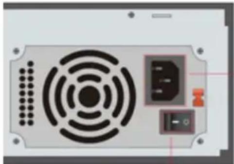
- For devices with internal power supply, please make sure that the AC 220/110V input selector is set correctly
natural_image
Top-down view of a computer drive chassis showing fan, buttons, and ports (no text or symbols visible)Contents
Contents 2
1 Introduction......6
1.1 Summary....6
1.2 Features....6
1.3 Front Panel Descriptions 9
1.4 Rear Panel Descriptions .... 10
1.5 Connections.... 12
2 Basic Operations Guide .... 14
2.1 Startup & Shutdown.... 14
2.1.1 Startup....14
2.1.2 Shutdown 14
2.2 Remote Controller....15
2.3 Mouse Control....16
2.4 Text-input Instruction....16
2.5 Other Button Operations 16
3 Wizard & Main Interface....17
3.1 Startup Wizard.... 17
3.2 Main Interface 23
3.2.1 Main Interface Introduction....23
3.2.2 Setup Panel....25
3.2.3 Main Functions....26
4 Camera Management....27
4.1 Camera Signal (Applicable only for DVRs)....27
4.1.1 Dynamic Hybrid (Supporting devices only)....27
4.2 Add/Edit Camera....28
4.2.1 Add Camera (Applicable only for NVRs and Hybrid DVR models)......28
4.2.2 Edit Camera's General Parameters 31
4.3 "In-Channel Sequence" (Only Applicable for NVRs)....33
4.3.1 Add "In-Channel Sequence" 33
4.3.2 Edit In-Channel Sequence 33
4.4 IPC Networking (Applicable only for NVRs and Hybrid DVR models) 33
4.4.1 IP Camera management....34
4.4.2 Device Management....34
5 Live-view Introduction: 35
5.1 Live-View Interfaces: 35
5.2 Fish-Eye Display: 36
5.3 Live View Digital Zoom: 37
5.4 Live-View Modes: 37
5.4.1 Customized Display Mode 37
5.4.2 Sequence 38
5.4.3 In Channel Sequence (Applicable for NVRs only)....40
5.4.4 Face Recognition (Applicable for Face Recognition NVRs only)......41
5.5 Emergency Live-View: 42
5.6 Image Configuration ....43
5.6.1 OSD Settings 43
5.6.2 Image Settings (Setting Interface) 43
5.6.3 Mask Settings 44
5.6.4 Water Mark Settings (Applicable for DVRs only)....44
5.6.5 Fish-Eye (Applicable for Supporting NVRs only) 45
5.6.6 Image Adjustment (Live-View Interface) 46
6 PTZ....48
6.1 PTZ Control Interface: 48
6.2 Preset Settings....50
7 Record & Disk Management....52
7.1 Record Configuration: 52
7.1.1 Mode Configuration: 52
7.1.2 Advanced Configuration....54
7.2 Encode Parameters Setting....54
7.3 Schedule Setting....55
7.3.1 Add Schedule 55
7.3.2 Record Schedule Configuration....57
7.4 Record Mode....57
7.4.1 Manual Recording....57
7.4.2 Scheduled Recording: 57
7.4.3 Motion Based Recording: 57
7.4.4 Sensor Based Recording: 57
7.4.5 Analytics Based Recording: 58
7.5 Disk Management: 58
7.5.1 Storage Mode Configuration....58
7.5.2 Disk Mode (Models supporting RAID only):....59
7.5.3 Physical Disk (Models supporting RAID only):....59
7.5.4 Array (Models supporting RAID only): 60
7.5.5 View Disk and S.M.A.R.T. Information: 60
8 Search, Playback & Backup....61
8.1 Instant Playback....61
8.2 Playback Interface Introduction ......61
8.3 Record Search, Playback & Backup....66
8.3.1 Search & Playback by Time-sliced Image....66
8.3.2 Search, Playback & Backup by Smart Search: 67
8.3.3 Search, Playback & Backup by Time: 68
8.3.4 Search, Backup & Playback by Event 72
8.3.5 Search & Playback by Tag....73
8.3.6 Snapshots 73
8.3.7 Backup Procedures....74
8.3.8 View Backup Status....74
9 Alarm Management 75
9.1 Sensor Alarm....75
9.2 Motion Alarm....76
9.2.1 Motion Configuration....76
9.2.2 Motion Alarm Handling Configuration 77
9.3 Analytics Configuration (Applicable for NVRs and Hybrid DVRs only). 77
9.3.1 Object Monitoring Configuration (IPC Channels Only)....78
9.3.2 Camera Tampering Configuration (IPC Channels Only)....79
9.3.3 Line Crossing Configuration 80
9.3.4 Sterile Area Configuration....81
9.3.5 Analytics Alarm Handling Configuration 81
9.4 General Fault Alarms 82
9.4.1 General Fault Handling Settings....82
9.4.2 IPC Offline Settings 82
9.5 Alarm Event Notification 84
9.5.1 Alarm-out 84
9.5.2 E-mail....84
9.5.3 Display 84
9.5.4 Buzzer 84
9.5.5 Push Message 85
9.6 Manual Alarm 85
9.7 View Alarm Status....85
10 Account & Permission Management 87
10.1 Account Management....87
10.1.1 Add User....87
10.1.2 Edit User....88
10.2 User Login & Logout 88
10.3 Permission Management 89
10.3.1 Add Permission Group 89
10.3.2 Edit Permission Group 89
10.4 Black and White List....89
10.5 Preview on Logout 90
10.6 Password Security 90
10.7 User Status: 91
11 Device Management....92
11.1 Network Configuration....92
11.1.1 TCP/ IPv4/6 Configuration....92
11.1.2 Port Configuration....93
11.1.3 DDNS Configuration....94
11.1.4 E-mail Configuration....96
11.1.5 UPnP Configuration 98
11.1.6 NAT Configuration....98
11.1.7 FTP Configuration....98
11.1.8 SNMP Configuration....99
11.1.9 View Network Status 99
11.2 Basic Configuration....99
11.2.1 General Settings 99
11.2.2 Date and Time Configuration 101
11.2.3 Layout settings: 101
11.2.4 POS settings: 102
11.3 Maintenance: 103
11.3.1 View Log 103
11.3.2 Factory Default.... 104
11.3.3 Device Software Upgrade....104
11.3.4 Cloud Upgrade 105
11.3.5 Backup and Restore.... 105
11.3.6 Auto Maintenance:....106
11.3.7 View Log 106
11.3.8 View System Information....107
12 Remote Surveillance....107
12.1 Mobile Client Surveillance.... 107
12.2 Web LAN Access 107
12.3 Web WAN Access 108
12.4 Web-Client 109
12.5 Web Remote Control.... 110
12.5.1 Remote Live-View 110
12.5.2 Remote Playback.... 113
12.5.3 Remote Backup 114
12.5.4 Remote Configuration.... 114
Appendix A: FAQ....115
Appendix B: Calculate Recording Capacity....121
Appendix C: RAID Types....122
Appendix C: Compatible Device List....123
1 Introduction
1.1 Summary
This series of devices running Ossia are designed to provide unconditional security for homes, offices, banks, schools, supermarkets, petrol service stations, residential quarters, factories, Etc. In can be accessed from local or remote locations.
The Ossia OS was designed specifically to answer the user's needs. It is based on the most advanced SOC technology and adopts a new and intuitive human GUI. This series of the devices is more powerful than any older device produced by Provision-ISR. It is easy to use while providing excellent image quality and system stability.
1.2 Features
Basic Functions
● Support live view, record and configuration of IP cameras
- Some Devices (NVR5 Series and above – Non-“E” models) support the latest H.265 (HEVC) video coding stream and a mixture input of H.265 and H.264 IP cameras. Ossia DVRs does not support H.265.
● Support standard ONVIF protocol*
● Support dual stream recording of each camera
● Support IPC Quick add*
● 4in1 Support for DVRs (AHD/CVI/TVI/CVBS)
- Support batch or single configuration of IP cameras (OSD, video parameters, mask, motion, alarms, Etc.)*
● Support a maximum of 8 user permission groups including Administrator, Advanced and Ordinary which are the default permission groups of the system
● Support a maximum of 16 users.
- Support a numerous web clients login at the same time (According to device's specs)
● Analytics support*
Live Preview Features:
- 4K×2K*/1920×1080/1280×1024 HDMI and 1920×1080/1280×1024 VGA high definition synchronous display (This may vary according to your model. Please refer to your device technical specs for more information)
● Multi-screen modes such as 1/4/6/8/9/16/25/32 (depends on model)
- Auto adjustment of the camera's image display proportion
- IPC audio monitoring (can be enabled or disabled)*
● Manual snapshot of the previewed camera
- Customized setting the sequence pages
● Support saving of the display modes. The saved modes can be called directly
● One channel operation tool bar
● Camera group view and scheme view in sequence and quick sequence view
● Motion detection and video masking
● Full PTZ control including setting up the presets and cruises
● Direct mouse control over the PTZ cameras including movement, zoom and focus.
● Intuitive Digital-Zoom can be controlled directly from the mouse wheel
● Image adjustment (only available for some cameras)
HDD Support:
● 3U Case support up to 16 SATA HDDs
● 2U Case support up to 8 SATA HDDs
● 1.5U Case support up to 4 SATA HDDs
● 1U Case support up to 2 SATA HDDs
● Small 1U/MM Case support up to 1 SATA HDD
● Each SATA interface of the device supports the HDDs with max 8TB storage capacity
● Some models support record and backup to an e-SATA HDD
Disk Management:
● The HDDs can be grouped for configuration and management.
● Each camera can be added into different disk group with different storage capacity
- Some devices support RAID
● The system allows batch formatting of the HDDs
Record Configuration:
● Support main stream and sub-stream recording at the same time.
● Batch or single configuration of the record stream
● Manual and auto record modes
● Schedule recording, sensor alarm recording and motion detection recording
- Configure different record streams for schedule recording and event recording setting
● Support record duration setting and recycle recording
● Support pre-alarm recording and post alarm recording configuration for event recording
● Support situation dependent recording.
Playback:
● Time scale operation in quick playback. Also, the playback date and time can be set easily by scrolling the mouse wheel. The intervals of the time scale can be zoomed in/out.
● Record searching by Image-slice/time/event/tag
● Time image slice searching by month, by day, by hour and by minute and time. The slice is displayed by image thumbnail
● Up to 16 channels to be searched by time
● Event searching by manual/motion/sensor events
● Tag searching (for tags manually added by user)
- Instant playback of selected camera within the live preview interface
● Up to 16 synchronous playback channels
Record Backup
● Backup through USB (U-disk, mobile HDD) or e-SATA** interface
- Backup by time/event/image searching
- Customized backup selection while playing back
● Up to 10 backup tasks running in the background
Alarm Management:
● Alarm schedule setting
● Supports enabling or disabling of motion detection, external sensor alarm input and exception alarms including IP address conflict alarm, disk I/O error alarm, disk full alarm, no disk alarm, illegal access alarm, network disconnection alarm and IPC offline alarm.
- Configurable alarm trigger
● Alarms can trigger PTZ Operation, snapshots, pop-up videos and more.
● Event notification modes: Alarm-out, pop-up video, pop-up message box, buzzer and E-mail
● E-mail schedule support
● Snapped images can be attached to the e-mail when alarm triggered
● Alarm information status for alarm-in, alarm-out, motion detection and exception alarm
● Alarm can be triggered and cleared manually
- System auto reboot when HDD or I/O exception happens – in order to restart and recover the HDD
Network Functions:
- TCP/IP and PPPoE, DHCP, DNS, DDNS, UPnP, NTP, SMTP, RTSP protocols
- “Allow & Block” lists according to IP or MAC addresses
● Multiple browser support for Windows and Mac OS (Must Support NPAPI Plug-ins)
- Remote configuration and maintenance including remote upgrading and remote system reboot
- Remote camera configuration of the device including video parameters, image quality, Etc.*
● Remote search, playback and backup.
● CMS or other management software can access the device and manage it.
● Support Cloud connection (NAT) and QR Code scanning by smart phones and tablets
● Support mobile surveillance by smart phones or tablets running iOS or Android OS
● Telnet function can be enabled or disabled by the user for remote maintenance
Other Functions:
● The device can be controlled and operated by the supplied mouse or remote controller
● Standard remote Mouse can be used (Not supplied)
- Quick device information view including basic details, camera status, alarm status, record status, network status, disk and backup status
● Support auto recognition of the display resolution
* For NVRs, Dynamic Hybrid and Hybrid DVRs only
**Supported models only
1.3 Front Panel Descriptions
The following descriptions are for reference only.
Type I (MM/Small 1U/1.5U Models):
| Name | Descriptions |
| REC | While recording, the light is blue |
| NET | When accessed by network the light is blue |
| PWR | When powered on , the light is blue |
Type II (2U Models):
| Name | Descriptions |
| Power | When powered on, the light is blue |
| HDD | The light turns blue when reading/writing HDD |
| Net | The light turns blue when the devices accesses the network |
| Backup | The light turns blue when backing up files and data |
| Play | The light turns blue when playing back video |
| REC | When recording, the light is blue |
| AUDIO /+ | 1. Adjust audio; 2. Increase the value in setup |
| P.T.Z /- | 1. Enter PTZ mode; 2. Decrease the value in setup |
| MENU | Enter Menu |
| INFO | Check the information of the device |
| BACKUP | Enter backup mode in live |
| SEARCH | Enter search mode in live |
| Exit | Exit the current interface |
| Manual record | |
| Play/Pause | |
| Speed down | |
| Speed up | |
| 1-9 | Input digital number and select camera |
| 0/-- | Input number 0, the number above 10 |
| Direction Key | Change direction |
| Multi-Screen Switch | Change the screen mode |
| Enter | Confirm selection |
| USB | To connect external USB device like USB mouse or USB flash |
1.4 Rear Panel Descriptions
In this section we will introduce you to a few samples of rear panels. Of course we cannot include all rear panels of all the available devices. Please take this manual as reference only.
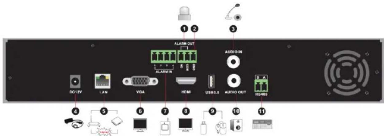
text_image
1 2 3 ALARM OUT AUDIO IN DC12V LAN VGA HDMI USB3.0 AUDIO OUT RS48S 4 5 6 7 8 9 10 11| No. | Name | Descriptions |
| 1 | ALARM OUT | Relay output; connect to external devices |
| 2 | GND | Ground connection |
| 3 | AUDIO IN | Audio input |
| 4 | DC12V | DC12V power input |
| 5 | LAN | Network port |
| 6 | VGA | Connect to VGA monitor |
| 7 | ALARM IN | Alarm inputs for connecting sensors |
| 8 | HDMI | Connect to HD display |
| 9 | USB | Connect USB storage device or USB mouse. USB3.0 interfaces will be colored in blue. |
| 10 | AUDIO OUT | Audio output |
| 11 | RS485 | Connect to keyboard. A is TX+; B is TX- |
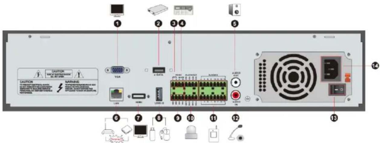
text_image
1 2 3 4 5 6 7 8 9 10 11 12 13 14 CAUTION WARNING LED/LED/LED/LED/LED/LED/LED/LED/LED/LED/LED/LED/LED/LED/LED/LED/LED/LED/LED/LED/LED/LED/LED/LED/LED/LED/LED/LED/LED/LED/LED/LED/LED/LED/LED/LED/LED/LED/LED/LED/LED/LED/LED/LED/LED/LED/LED/LED/LED/LED/LED 13 VGA e-SATA LAN HDMI USB3.0 ALABRUT ALABRUT AUDIO AC-DCN LCD| No. | Name | Descriptions |
| 1 | VGA | Connect to VGA monitor |
| 2 | e-SATA | Connect to HDD with e-SATA interface |
| 3 | RS485 Y/Z interface | Unavailable |
| 4 | RS485 A/B interface | Connect to keyboard. A is TX+; B is TX- |
| 5 | AUDIO OUT | Audio output |
| 6 | LAN | Network port |
| 7 | HDMI | Connect to HD display |
| 8 | USB | Connect USB storage device or USB mouse. USB3.0 interfaces will be colored in blue. |
| 9 | GND | Ground connection |
| 10 | ALARM OUT | Relay output; connect to external devices |
| 11 | ALARM IN | Alarm inputs for connecting sensors |
| 12 | AUDIO IN | Audio input |
| 13 | Power Switch | Press the switch to turn on/off the device |
| 14 | Power Supply | Power supply interface |
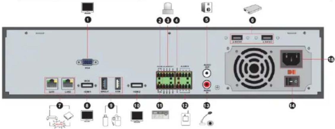
text_image
Labeled diagram of a computer rack showing ports, connectors, and hardware components with numbered annotations| No. | Name | Descriptions |
| 1 | VGA | Connect to monitor |
| 2 | RS485 Y/Z interface | Unavailable right now |
| 3 | ALARM OUT | Relay output; connect to external alarm |
| 4 | GND | Grounding |
| 5 | AUDIO OUT | Audio output; connect to sound box |
| 6 | e-SATA1/ e-SATA2 | Connect to HDD with e-SATA interface |
| 7 | LAN1/LAN2 | Network ports |
| 8 | HDMI1 | Connect to 4K×2K high definition display device |
| 9 | USB3.0/USB | USB3.0/2.0 interface, connect storage device or mouse |
| 10 | HDMI2 | Connect to 1920×1080 high definition display device |
| 11 | RS485 A/B interface | Connect to keyboard. A is TX+; B is TX- |
| 12 | ALARM IN | Alarm inputs for connecting sensors |
| 13 | AUDIO IN | Audio input |
| 14 | Power Switch | Press the switch to turn on/off the device |
| 15 | Power Supply | Power supply interface |
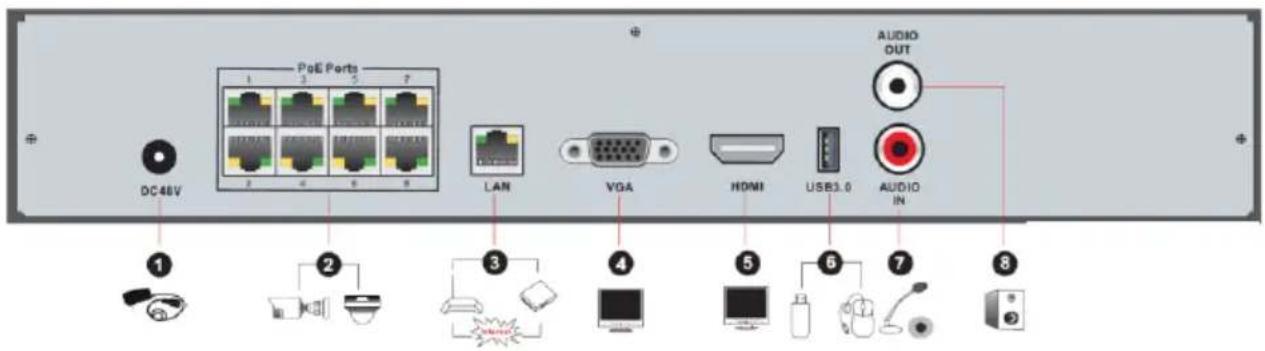
text_image
PoE Ports DC 48V LAN VGA HDMI USB3.0 AUDIO OUT 1 2 3 4 5 6 7 8| No. | Name | Descriptions |
| 1 | Power Supply | DC48V power supply interface |
| 2 | PoE port | 8 PoE network ports; connect to 8 PoE IP cameras |
| 3 | LAN | Network port |
| 4 | VGA | Connect to VGA monitor |
| 5 | HDMI | Connect to HD display (4K Ultra HD Supported) |
| 6 | USB3.0 | USB3.0 interface, connect USB storage device or USB mouse |
| 7 | AUDIO IN | Audio input |
| 8 | AUDIO OUT | Audio output |
1.5 Connections
● Video Output Connections
Video Output: Supports VGA/HDMI/CVBS/Spot video output (Depends on models). You can connect to monitor through these video output interfaces simultaneously or independently.
- Audio Connections
Audio Input: Connect to microphone, pickup, etc.
Audio Output: Connect to headphone, sound box or other audio output devices.
- Alarm Connections
Only selected models support this function. See below 16 CH alarm inputs and 1 CH alarm output for example.
Alarm Input (Availability depends on model):
Alarm IN 1\~16 are 16CH alarm input interfaces. There are no type requirements for sensors. NO type and NC type are both available and can be configured from the device interface. The method to connect sensors to the device is as shown below:
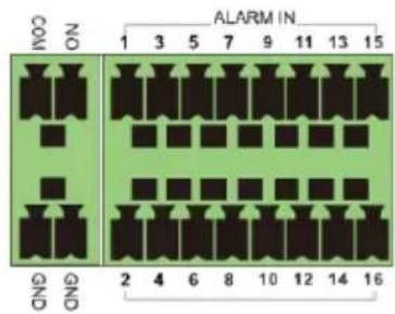
text_image
ALARM IN 1 3 5 7 9 11 13 15 COM NO 2 4 6 8 10 12 14 16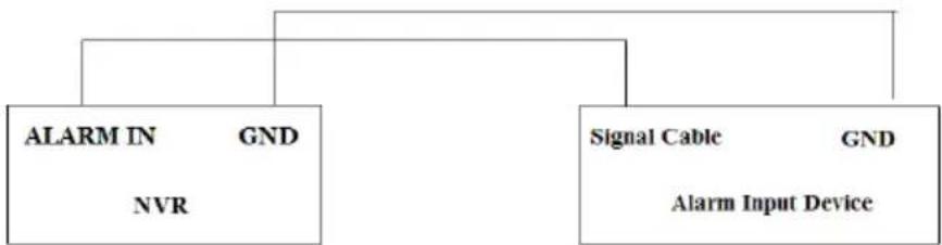
flowchart
graph TD
    A["ALARM IN"] --> B["NVR"]
    C["Signal Cable"] --> D["Alarm Input Device"]
    E["GND"] --> F["Alarm Input Device"]
The alarm input is an open/close relay. If the input is not an open/close relay, please refer to the following connection diagram:
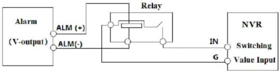
flowchart
graph LR
    A["Alarm (V-output)"] --> B["ALM (+)"]
    A --> C["ALM(-)"]
    B --> D["Relay"]
    C --> D
    D --> E["NVR"]
    E --> F["Switching Value Input"]
    F --> G["IN"]
    F --> H["G"]
Alarm Output (Availability depends on model):
The way to connect alarm output device:
Pull out the green terminal blocks and loosen the screws in the alarm-out port. Then insert the signal wires of the alarm output devices into the port of NO and COM separately. Finally, tighten the screws. Provided that the external alarm output devices need power supply, you can connect the power supply as per the following figures.
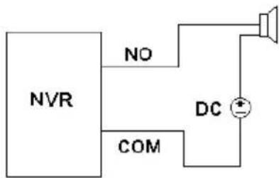
flowchart
graph TD
    A["NVR"] -->|NO| B["Speaker"]
    A -->|COM| C["DC Symbol"]
    C --> B
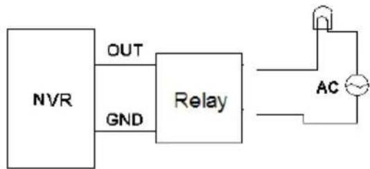
flowchart
graph LR
    A["NVR"] -->|OUT| B["Relay"]
    A -->|GND| B
    B --> C["AC"]
RS485 Connection (Availability depends on model):
There are two types of RS485 interfaces:
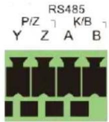
text_image
RS485 P/Z K/B Y Z A B(Type 1)

B A
RS485
(Type 2)
Type 1: The P/Z is for PTZ cameras – Not applicable for NVR devices. The K/B interface is used to connect the C06 control keyboard.
Type 2: The RS485 interface is used to connect control keyboard and PTZ cameras (This connector cannot be used for PTZ control in NVR devices. A is TX+; B is TX-.
2 Basic Operations Guide
2.1 Startup & Shutdown
Please make sure all the connections are done properly before you power on the device. Proper startup and shutdown are crucial for prolonging the lifespan of the device.
2.1.1 Startup
① Connect the output display device to the VGA/HDMI interface of the device.
② Connect the USB mouse and network cable
③ Connect the power. The device will boot and the power LED would turn blue.
④ A WIZARD window will pop up (you should select the display language the first time you use the device). Refer to 3.1 Startup Wizard for details.
2.1.2 Shutdown
You can power off the device by using the remote controller or USB mouse.
By remote controller:
① Press the power button. This will take you to a shutdown window. The unit will power off after a while by clicking “OK” button.
② Disconnect the power.
By mouse:
① Click Start→Shutdown to pop up the Shutdown window. Select “Shutdown” in the window. The unit will power off after a while by clicking “OK” button.
② Disconnect the power.
2.2 Remote Controller (Availability depends on model):
① Open the battery cover of the remote controller and insert two AAA size batteries.
② When placing the batteries. Please ensure the correct polarity (+ and -).
③ Replace the battery cover.
Key points to check in case the remote doesn't work.
- Check batteries polarity.
- Check if the batteries are not dead
- Check IR controller sensor for any interference.
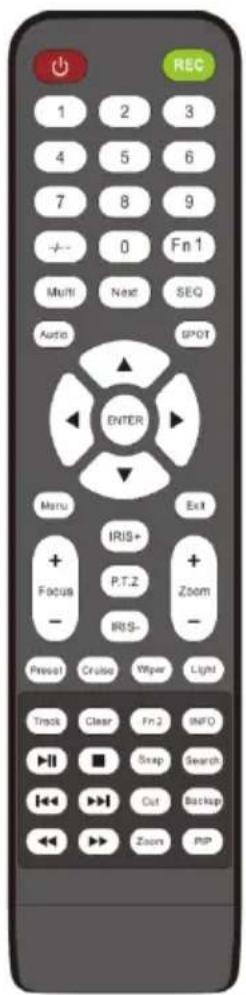
text_image
REC 1 2 3 4 5 6 7 8 9 - - 0 Fn1 Multi Next SEQ Audio SPOT ENTER Menu + IRIS+ Focus P.T.Z + - IRS- Press! Cruise Wiper Light Exit Zoom - Preview Clear Fn2 INFO Swap Search Cut Backup Zoom PIP| Button | Function | |
| Power Button | Switch off—to stop the device | |
| Record Button | To start recording | |
| -/-- /0-9 | Input number or choose camera | |
| Fn1 Button | Unavailable temporarily | |
| Multi Button | To choose multi screen display mode | |
| Next Button | To switch the live image | |
| SEQ | To go to sequence view mode | |
| Audio | To enable audio output in live mode | |
| Switch | No function temporarily | |
| Direction button | To move cursor in setup or pan/title PTZ | |
| Enter Button | To confirm the choice or setup | |
| Menu Button | To go to menu | |
| Exit Button | To exit the current interface | |
| Focus/IRIS/Zoom/PTZ | To control PTZ camera | |
| Preset Button | To enter into preset setting in PTZ mode | |
| Cruise Button | To go to cruise setting in PTZ mode | |
| Track Button | No track function temporarily | |
| Wiper Button | No function temporarily | |
| Light Button | No function temporarily | |
| Clear Button | No function temporarily | |
| Fn2 Button | No function temporarily | |
| Info Button | Get information about the device | |
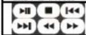 | To control playback. Play(Pause)/Stop/Previous Frame/Next Frame/Speed Down/Speed Up | |
| Snap Button | To take snapshots manually | |
| Search Button | To go to search mode | |
| Cut Button | No function temporarily | |
| Backup Button | To go to backup mode | |
| Zoom Button | To zoom in the images | |
| PIP Button | No function temporarily | |
Note:
Click on the P.T.Z button to enter the PTZ interface. Once in the PTZ interface, you can use preset, cruise, track, wiper or light button to enable the relevant function.
2.3 Mouse Control
➢ Mouse control in Live Preview & Playback interface
In the live preview & playback interface, double click on any camera window to show the video in single screen mode; double click the window again to restore it to the previous split.
If the interfaces display in full screen, move the mouse to the bottom or to the right side of the interface to pop up the relevant tool bar. The tool bar will disappear automatically after you move the mouse away from it;
Mouse control in text-input
Move the mouse to the text-input box and click the box. When required to input text the keyboard will pop up automatically.
Note: The mouse is the default controller for all operations unless mentioned otherwise.
2.4 Text-input Instruction
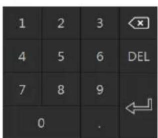
text_image
1 2 3 4 5 6 DEL 7 8 9 0 .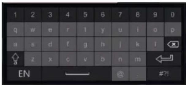
text_image
1 2 3 4 5 6 7 8 9 0 q w e r l y u i o p a s d f g h j k l x a z x c v b n m ← EN — @ . #?!The system includes two input keyboard layout as shown the above pictures. The left box is the number input keyboard and the right box is the general input keyboard which provides inputs of numbers, letters and punctuation characters as shown below
| Button | Meaning | Button | Meaning |
 | Backspace key | Switch to punctuation characters | |
 | Delete Key | Enter key | |
 | Switch key between upper and lower-case letters | Space key |
2.5 Other Button Operations
| Button | Meaning | ||
 | Show the menu list. | ||
 | Change the sequence order within the list. | ||
 |  | Change the camera display mode. | |
 | Close the current interface. | ||
 | Go to the earliest date of camera recording. | ||
 | Go to the latest date of camera recording. | ||
3 Wizard & Main Interface
3.1 Startup Wizard
On each startup, the disk icons will be shown on the top of the interface. You can view the number and status of each disk quickly and conveniently through these icons
1) No disk
2) Unavailable disk
3) R/W available disk
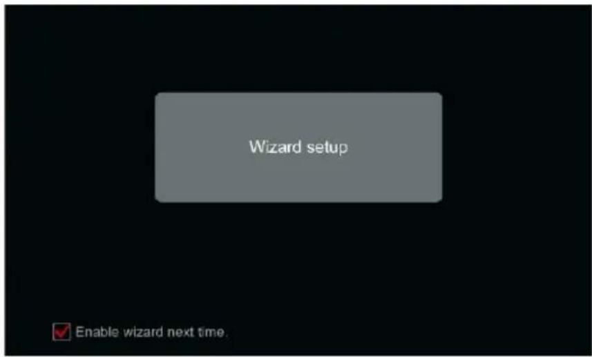
You can quickly and easily configure the device using the setup wizard. The wizard can also be skipped and will be shown in the next startup unless the “Enable wizard next time” was unticked. Skipping the wizard will automatically set the default password to “123456”
text_image
Wizard setup Enable wizard next time.Click "Wizard Setup" to start. The setting steps are as follows:
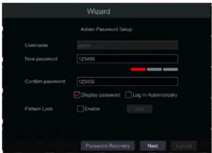
① Admin settings. (Appears only one time – on the first system startup): Set your own admin password or use the default when you use the wizard for the first time (the default username is admin. skipping this part will set the default password to “123456”); It is highly advisable to change the default password.
text_image
Wizard Admin Password Setup Username New password 123456 Confirm password 123456 ✓ Display password □ Log In Automatically Pattern Lock □ Enable Enter Password Recovery Next CancelClick on “Password Recovery” to set questions and answers for password recovery. If you will ever forget the password – these questions will be used to restore the password to factory default. Please refer to Q4 in Appendix A FAQ for details. Skipping this step will force you to contact the technical support in case the password will be forgotten. There is no other way for the user to independently recover the admin password except of this method.
In this step you can also set a “Pattern” password that could be used for login into the device. It is simpler and more fluid to use the pattern lock when using a mouse and screen only (without a keyboard). If you wish to use pattern lock, enable it and click “edit” to set it as follows:
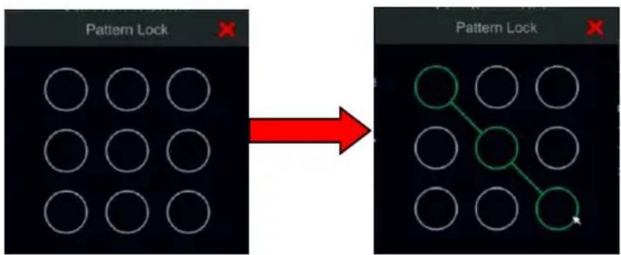
flowchart
graph LR
    A["Pattern Lock"] --> B["3x3 Grid"]
    style A fill:#fff,stroke:#000
    style B fill:#fff,stroke:#000
    style_C["Red Arrow"] --> D["3x3 Grid with green circle and arrow"]
Click "Next" to continue or click "Cancel" to exit the wizard.
② Date and Time Configuration. (Appears only one time – on the first system startup): The date and time of the system must be configured when you use the wizard for the first time. Set the time zone, system time, date format and time format. The DST will be enabled by default if the time zone selected includes DST. The “Method” line allows you to change from manual setting to NTP (Network Time Protocol) setting which will synchronize the time with the configured NTP server. The default NTP server is “provisionisr-time.com” but you can change it to any other NTP server as you wish. Click “Next” to continue.
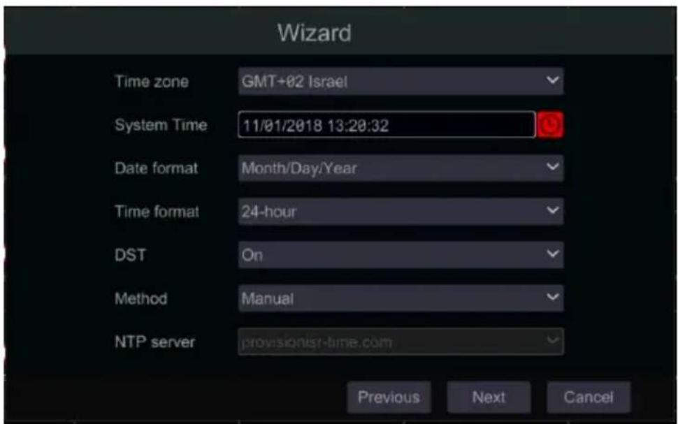
text_image
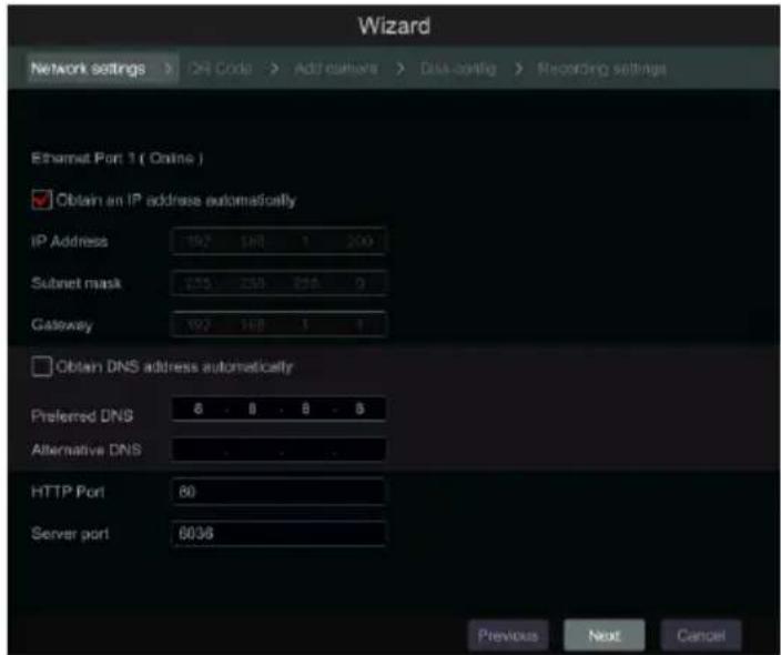
Wizard Time zone GMT+02 Israel System Time 11/01/2018 13:20:32 Date format Month/Day/Year Time format 24-hour DST On Method Manual NTP server provisionist-time.com Previous Next Cancel③ Network Settings - general. Check "Obtain an IP address automatically" and "Obtain DNS automatically" to get the IP address and DNS automatically (You must have a DHCP Service enabled in your network). Uncheck it in order to input it manually. Input the HTTP port, RTSP port and Server port (please see 11.1.2 Port Configuration for details). Click "Next" to continue.
text_image
Wizard Network settings > 24 Code > Add culture > Data-config > Recording settings Ethernet Port 1 ( Online ) Obtain an IP address automatically IP Address 197 198 1 200 Subset mask 253 254 255 2 Gateway 197 198 1 1 Obtain DNS address automatically Preferred DNS 6 8 9 8 Alternative DNS HTTP Port 80 Server port 6036 Previous Next CancelPicture reference for DVR/Non-PoE NVR
Network setting – PoE NVRs:
If you use PoE NVR, the state of the internal ethernet port will be shown on the interface as seen on the picture below. Please refer to 11.1.1 TCP/IPv4 Configuration for detailed introduction of the internal ethernet port.
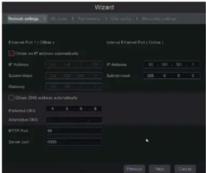
text_image
Wizard Network settings > OR Code > Add camera > Disk config > Recording settings Ethernet Port 1 ( Offline ) Internal Ethernet Port ( Online ) Obtain an IP address automatically IP Address 182 150 1 . 290 IP Address 10 . 151 . 151 . 1 Subnet mask 236 250 255 4 Subnet mask 256 . 0 . 0 . 0 Gateway 172 158 1 Obtain DNS address automatically Preferred DNS 8 . 8 . 8 . 8 Alternative DNS HTTP Port 80 Server port 6036 Previous Next CancelPicture reference for PoE NVR
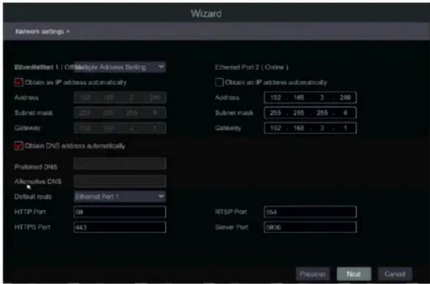
Professional models with 2 Ethernet ports: Some devices support 2 ethernet ports. The ports can work in 2 ways – “Multiple Address Setting” which means that the device will get 2 IP addresses and both addresses are always active. The second option is “Network fault tolerance” which means that only the primary ethernet port is active at a given time. If the primary network develops a fault – the device will automatically switch to the secondary ethernet port. Please refer to 11.1.1 TCP/IPv4 Configuration for additional information.
For “Multiple Address Setting” you will need to set 2 different addresses (Static or DHCP) and one DNS address. You can set the default ethernet port for DNS routing.
For “Network fault tolerance” you will need to set a single address (Static or DHCP) and DNS address. The 2 networks should be in the same IP Segment. You can also set the primary ethernet card.
text_image
Wizard Network settings > WavePatient 1 ( Off Multiple Address Setting ) Obtain an IP address automatically Address 162 168 2 290 Subnet mask 255 255 255 9 Gateway 162 168 2 2 1 Obtain DNS address automatically Preferred DNS Alternative DNS Default route Ethernet Port 1 HTTP Port 89 HTTPS Port 443 Ethernet Port 2 ( Online ) Obtain an IP address automatically Address 192 . 168 . 3 . 290 Subnet mask 255 . 255 . 255 . 9 Gateway 192 . 168 . 3 . 1 RTSP Port 554 Server Port 5936 Previous Next Cancel④ QR Code: You can enable the NAT service and scan the QR Code using the “Provision Cam 2” mobile application to quickly connect to the device. Please refer to 12.1 Mobile Surveillance for additional information.
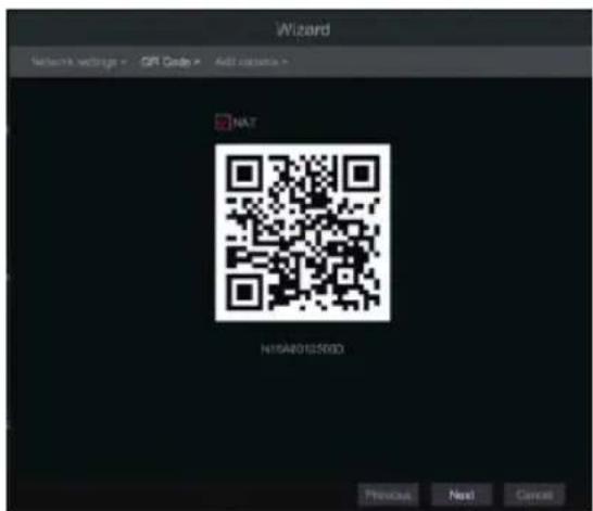
text_image
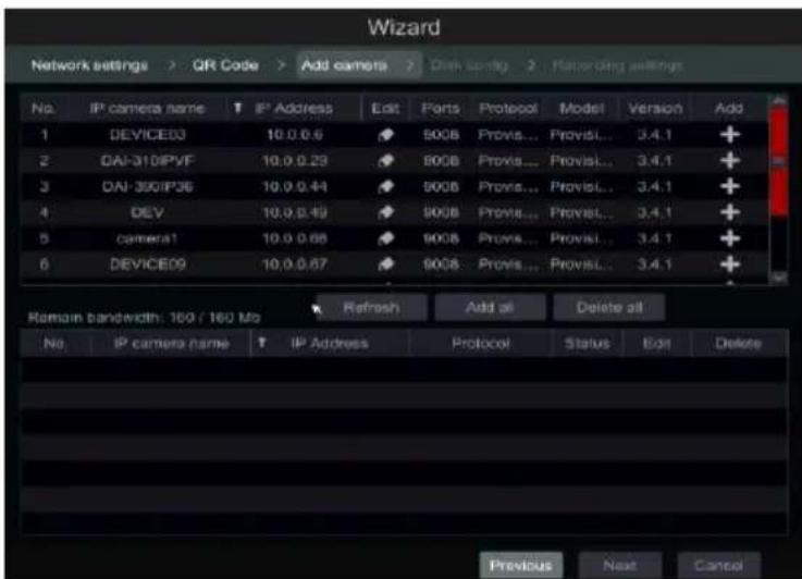
Wizard Network Settings - OR Code - Add version - NAT NAT/0125RBD Previous Next Cancel⑤ Add Camera. This section is available only in NVRs and Hybrid DVRs. It is applicable for IP cameras only. Connected analog cameras will be displayed automatically. Click “Refresh” to refresh the list of available IP cameras and click + to add the checked camera. Click “Add All” to add all the cameras in the list. Click 📄 to delete the added camera. Click “Delete All” to delete all the added cameras.
text_image
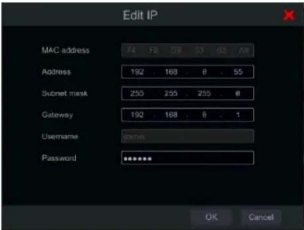
Wizard Network settings > QR Code > Add camera > Dash config > Filtering settings No. IP camera name T IP Address Edit Ports Protocol Model Version Add 1 DEVICES3 10.0.0.6 9008 Provis... ProvisL... 3.4.1 + 2 DAI-31DIPVF 10.0.0.29 9008 Provis... ProvisL... 3.4.1 + 3 DAI-350IP36 10.0.0.44 9008 Provis... ProvisL... 3.4.1 + 4 DEV 10.0.0.49 9008 Provis... ProvisL... 3.4.1 + 5 camera1 10.0.0.66 9008 Provis... ProvisL... 3.4.1 + 6 DEVICES9 10.0.0.67 9008 Provis... ProvisL... 3.4.1 + Refresh Add all Delete all Remain bandwidth: 160 / 160 Mo Refresh Add all Delete all No IP camera name T IP Address Protocol Status Edit Delete Previous Next CancelClick to edit the network parameters of the selected IP camera as shown on the left below. Input the new IP address, subnet mask and gateway. Fill the current username and password of the camera. Click “OK” to save the settings.
text_image
Edit IP MAC address 74 FB 128 03 62 AW Address 192 . 168 . 0 . 55 Subnet mask 255 . 255 . 255 . 0 Gateway 192 . 168 . 0 . 1 Username EDITOR Password ******** OK Cancel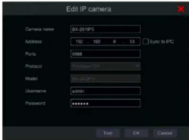
text_image
Edit IP camera Camera name BX-291IP5 Address 192 . 168 . 0 . 55 Sync to IPC Ports 9988 Protocol Password:ISP Model BX-342IP5+ Username admin Password ******** Test OK CancelClick to edit the added camera as shown on the above right. Input the new camera name, IP address and port. Fill the current username and password of the camera. You can click “Test” to test the effectiveness of the filled information. Click “OK” to save the settings. You can change the IP camera name only when the camera is added and online. Click “Next” to continue.
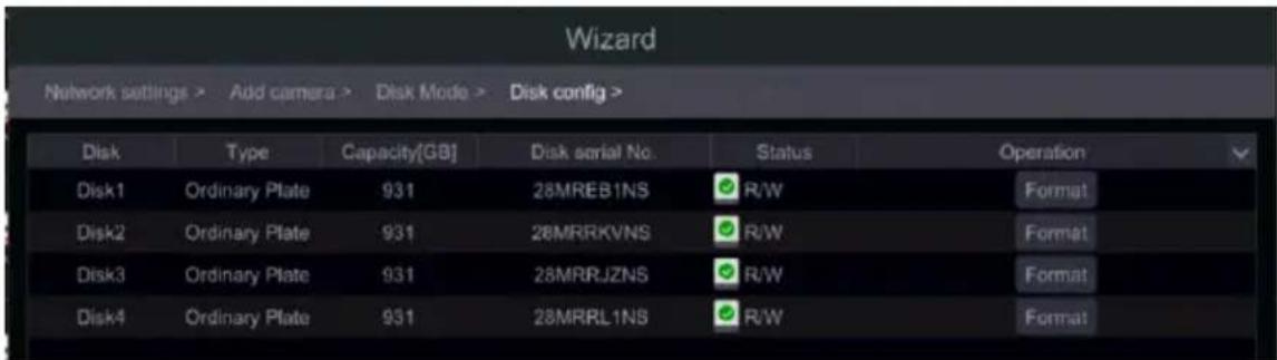
⑥ Disk Settings. You can view the disk status, number, capacity and serial number. Click “Format” to format the disk. Click “Next” to continue.
text_image
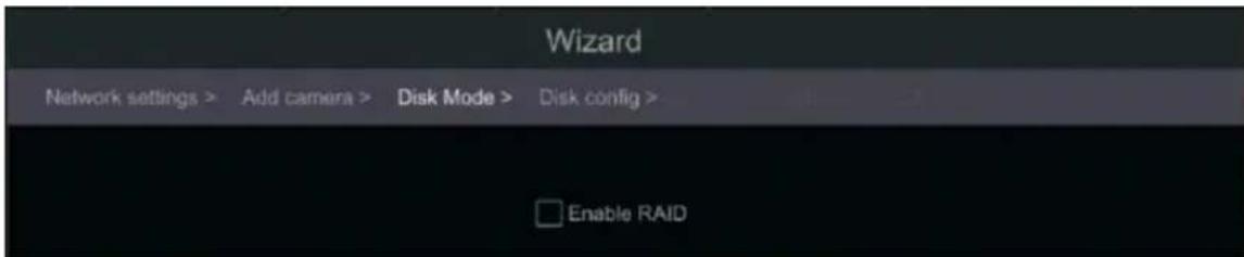
Wizard Network settings > Add camera > Disk Mode > Disk config > Disk Type Capacity[GB] Disk serial No. Status Operation Disk1 Ordinary Plate 931 28MREB1NS R/W Format Disk2 Ordinary Plate 931 28MRRKVNS R/W Format Disk3 Ordinary Plate 931 28MRRJZNS R/W Format Disk4 Ordinary Plate 931 28MRRL1NS R/W FormatModels Supporting RAID: These models will have another step – “Disk Mode”. Here you will be able to enable RAID. After confirmation – The device will prompt for a reboot.
text_image
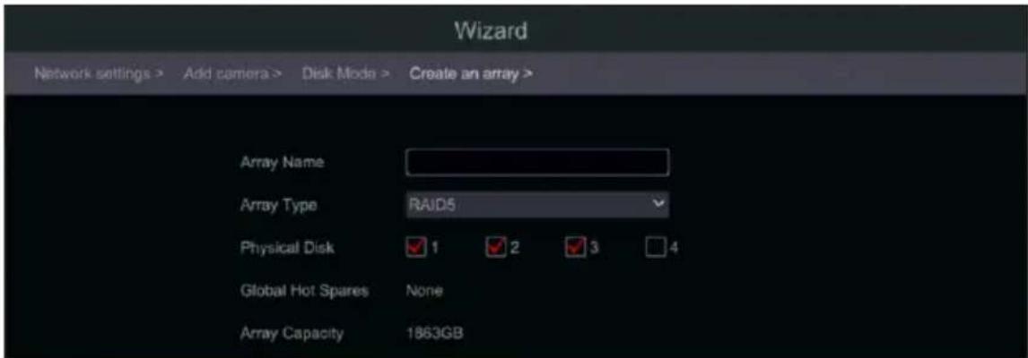
Wizard Network settings > Add camera > Disk Mode > Disk config > Enable RAIDAfter the reboot, there will be a new step in the wizard – “Create an array”
text_image
Wizard Network settings > Add camera > Disk Mode > Create an array > Array Name Array Type RAJD5 Physical Disk 1 2 3 4 Global Hot Spares None Array Capacity 1863GBSet the array as you wish and click “next” to continue. You can find further explanation about RAID in the appendix at the end of this manual.
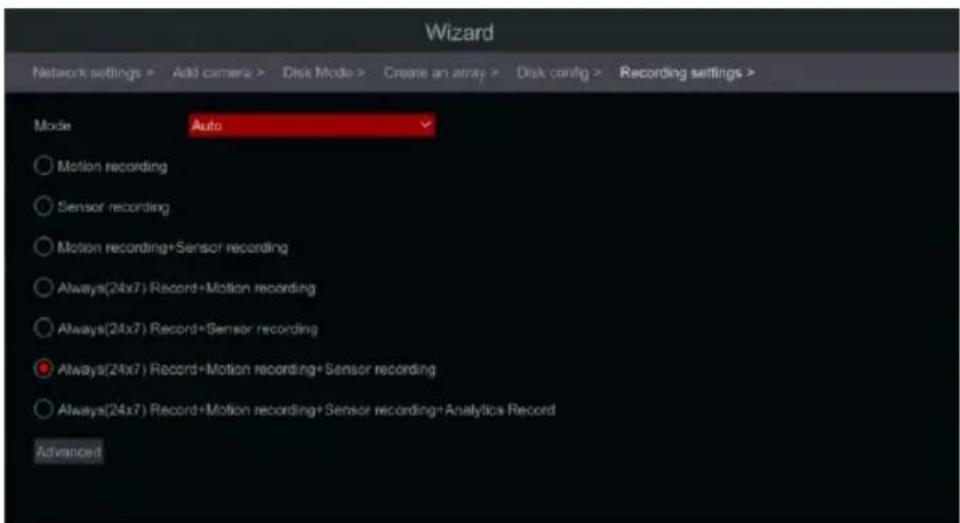
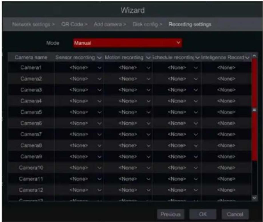
Record Settings. Two record modes are available: Auto and Manual. See 7.1.1 Mode Configuration for details.
Auto: Select the desired auto mode in the interface as shown below and click “OK” button to save the settings. You can use the “Advanced” button to create new combinations for recording.
text_image
Wizard Network settings > Add camera > Disk Mode > Create an array > Disk config > Recording settings > Mode Auto ○ Motion recording ○ Sensor recording ○ Motion recording+Sensor recording ○ Always(24x7) Record+Motion recording ○ Always(24x7) Record+Sensor recording ● Always(24x7) Record+Motion recording+Sensor recording ○ Always(24x7) Record+Motion recording+Sensor recording+Analytics Record AdvancedManual: After switching to manual, set the schedule for “Sensor Record”, “Motion Record” and “Schedule Record” of each camera. (You can choose all together by clicking on ▼. Click “OK” to save the settings.
text_image
Wizard Network settings > QR Code > Add camera > Disk config > Recording settings Mode Manual Camera name Sensor recording Motion recording Schedule recording Intelligence Record Camera13.2 Main Interface
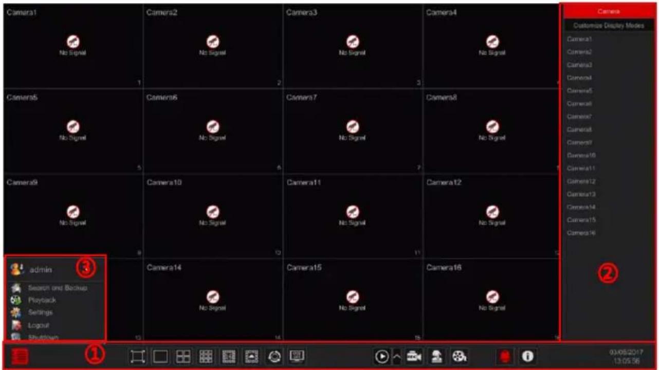
3.2.1 Main Interface Introduction
text_image
Camera1 No Signal Camera2 No Signal Camera3 No Signal Camera4 No Signal Camera5 No Signal Camera6 No Signal Camera7 No Signal Camera8 No Signal Camera9 No Signal Camera10 No Signal Camera11 No Signal Camera12 No Signal Camera13 Camera14 Camera15 Camera16 No Signal admin Search and Backup Playback Settings Logout Shutdown Camera Customize Display Modes Camera1 Camera2 Camera3 Camera4 Camera5 Camera6 Camera7 Camera8 Camera9 Camera10 Camera11 Camera12 Camera13 Camera14 Camera15 Camera16 03/05/2017 13:05:36Operations bar (①) icon description:
| Button | Meaning | |
 | Start button. Click it to pop up the menu (3). | |
 | Full screen button. Click it to switch to full screen mode; click it again to exit the full screen mode. | |
 | Screen split mode buttons. | |
 | Dwell button (see 5.2.2 Quick Sequence View and 5.2.4 Scheme View In Sequence for details). | |
 | Click it to enable OSD; click [OSD] disable OSD. | |
 | Click [to set the default playback time for in-channel instant playback (8.1 Instant Playback) and all channel playback (8.2 Playback Interface Introduction); click [to activate quick playback for all channels - going back to the specified time. For instance, if you choose “5 minutes ago” as the default playback time, you can playback the record from the past five minutes. | |
 | Manual record button. Click it to enable/disable manual record. | |
 | Manual alarm button. Click it to manually trigger or clear the alarm-out | |
 | Information button. Click it to view system information. | |
Introduction of area ② :
A) Click “Camera” to view all the cameras available for display. Either select one window on the left side of the interface and double click on the camera name you wish to view in the selected window or drag a camera name from the right pane to the selected window on the left.
B) Click “In-Channel Sequence” to view all the configured “In-Channel Sequence” groups list; Select a group in the list to view all the cameras related to that group. (Refer to 4.2 Add/Edit In-Channel Sequence for detailed information). Either select one window on the left side of the interface and double click on the group you wish to view in the selected window or drag a group name from the right pane to the selected window on the left.
C) Click “Display Presets” to view your saved presets (refer to 5.2.1 Preview By Display Presets for detailed explanation of the display presets). Double click on the desired display preset from the list to activate it.
Introduction of area (③):
| Icon / Button | Meaning | ||
 | admin | Showing the current user name | |
 | Search and Backup | Record search and backup interface, see 8.3 Record, Search, Playback & backup for details. | |
 | Playback | Playback interface .see 8.2 Playback Interface Introduction for details. | |
 | Settings | Setup panel, see 3.2.2 Setup Panel for details. | |
 | Logout | Log out of the system. | |
| [4WY9] | Shutdown | Perform “Logout”, “Reboot” or “Shutdown” | |
3.2.2 Setup Panel
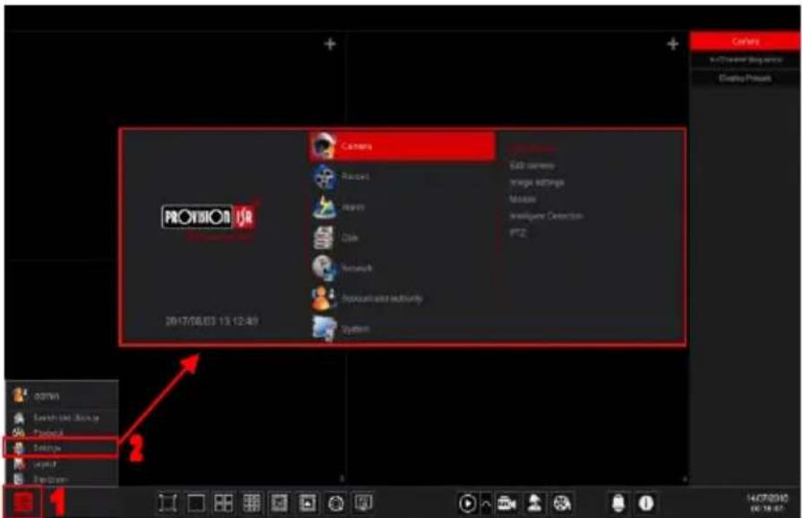
Click Start→Settings to pop up the setup panel as shown below. The setup panel includes seven categories. Each category contains sub-categories that will link you to the desired configuration interface.
text_image
PROVISION 2017/08/03 13:12:45 Camera Radar Rear Color Network Reputant and authority System Edit camera Image settings Measure Intelligent Detection PTZ. Options admin Search tool, Manage Project A Settings Impact OptionsHere we take Camera category as an example. The Camera Category provides links such as “Add Camera”, “Edit Camera”, “Image Settings”, “Motion” and “PTZ”. Click Camera and “Add Camera” to go to the camera management interface as shown below.
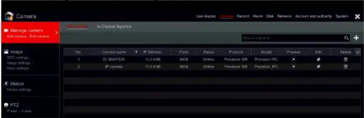
text_image
Camera Live display Record Alarm Disk Network Account and authority System Manage camera Add camera : Edit camera In-Channel Sequence Search cameras No. Camera name IP Address Ports Status Protocol Model Preview Edit Delete 1 DI-390IPS38 10.0.0.68 9008 Online Provision ISR Provision IPC 2 IP Camera 10.0.0.68 9008 Online Provision ISR Provision IPC Motion Motion settings PTZ Preset : CrudeClick the main categories on the top of the screen to go to corresponding interface. Refer to the picture below. For instance, you can go to system setup interface by clicking "System" tag.
Live display Camera Record Alarm Disk Network Account and authority System
3.2.3 Main Functions
Camera
Offers functions such as Camera Management (see Chapter 4 Camera Management for details), Image Settings (see 5.3 Preview Image Configuration for details), Motion (see 9.2.1 Motion Configuration for details) and PTZ (see Chapter 6 PTZ for details).
Record
This category covers Encode Parameters and Record Schedules. Please see Chapter 7 Record & Disk Management for details.
Disk
Her you will find Disk Management, Storage Mode and Disk Information. Please see Chapter 7 Record & Disk Management for details.
> Alarm
Configure Sensor and Motion Alarm Handling and Alarm Out Settings. Please see Chapter 9 Alarm Management for details.
Network
This category contains TCP/IPv4, DDNS, Port, E-mail and Network Status. Please see 11.1 Network Configuration for details.
Account and Authority
This category covers Account Management (see 10.1 Account Management for details) and Permission Management (see 10.3 Permission Management for details).
System
The category shows Basic Configuration (see 11.2 Basic Configuration for details), Device Information (see 11.7 View System Information for details), Log Information (see 11.6 View Log for details) and Configuration File Import & Export (see 11.5 Backup and Restore for details).
4 Camera Management
4.1 Camera Signal (Applicable only for DVRs)
All of the DVRs sunning Ossia OS support 4in1 technology (AHD / CVI / TVI / Analog). The default setting for video signal is “Auto” which means that the DVR will automatically recognize the camera signal and device which technology it is using. In some cases, the auto recognition fails – which will cause the video to come up in black & white or not to come up at all. In such cases, you will have to set the signal manually.
① Click Start→Settings→Camera→Camera Signal
② Choose the relevant channel (By number) and set the signal to the required one (Choose out of Auto/CVI/TVI). CVBS signal will be recognized automatically in all conditions.
| Camera | Analog/IP | ✓ | Signal | ✓ | Lite | ✓ |
| [A01] | Analog | ✓ | Auto | ✓ | Off | ✓ |
| [A02] | Analog | ✓ | Auto | ✓ | Off | ✓ |
| [A03] | Analog | ✓ | Auto | ✓ | Off | ✓ |
| [A04] | Analog | ✓ | Auto | ✓ | Off | ✓ |
③ If the DVR support “Lite” technology, you will see a “lite” column in this window. Selection of Lite will change the recording resolution to “Lite” and change the FPS from Half-Real-Time to Real-Time.
4.1.1 Dynamic Hybrid (Supporting devices only)
Dynamic hybrid allows you to choose weather a channel will perform as an HD Analog channel or as an IP Channel. Each device supporting Dynamic Hybrid has its own capabilities and restrictions. Please refer to the device's product specs in order to learn more on your device capabilities.
Configuring Dynamic Hybrid:
① Click Start→Settings→Camera→Camera Signal
② On the “Analog/IP” column, choose between Analog and IP.
③ Confirm. Upon confirmation the device will prompt for reboot. After the reboot, the selected channel will be as defined.
Note: Analog channels will be converted to IP even if there is a camera connected to it. IP channels till not be allowed to be converted if there is a camera configured on it.
4.2 Add/Edit Camera
4.2.1 Add Camera (Applicable only for NVRs and Hybrid DVR models)
For Non-Hybrid DVRs: the camera will be displayed automatically once connected to the BNC port. If the image does not appear on the screen please check the camera's power supply and video connection.
For NVRs and Hybrid DVRs: The device's network parameters should be configured before adding IP cameras (see 11.1.1 TCP/IPv4 Configuration for details).
Referring to the pictures below, Click on Add Camera in the setup panel or ✕ in the top right corner of the preview window to pop up the “Add Camera” window as shown below. You can use the “quick add” interface to add an IP Camera or add it manually.
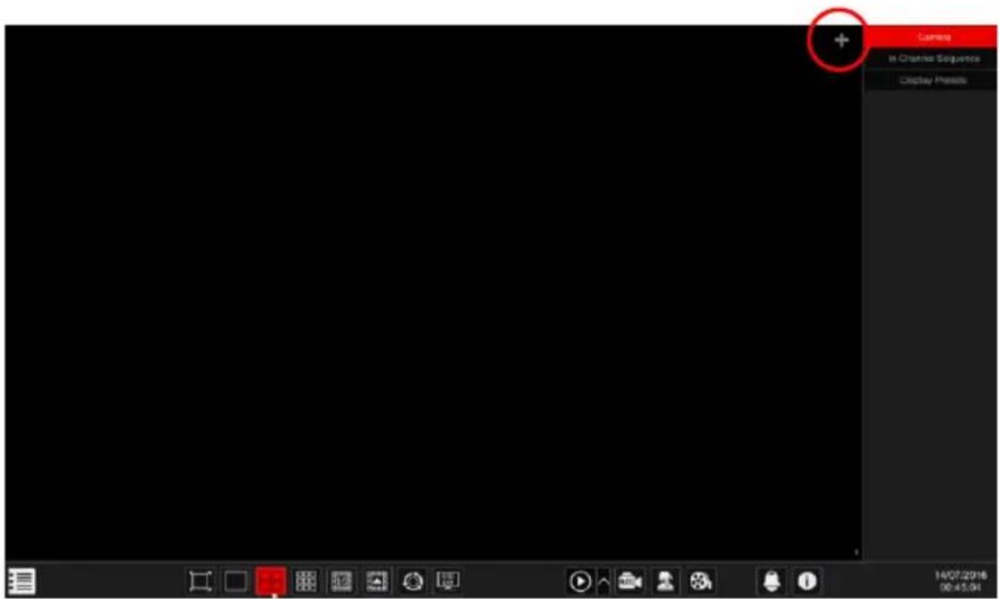
text_image
Current In Channel Sequence Display Pixels 14/07/2016 00:45:04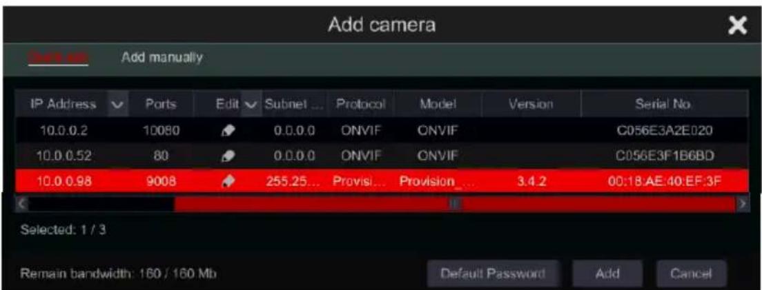
text_image
Add camera Subs as Add manually IP Address Ports Edit Subnet... Protocol Model Version Serial No 10.0.0.2 10080 0.0.0.0 ONVIF ONVIF C056E3A2E020 10.0.0.52 80 0.0.0.0 ONVIF ONVIF C056E3F1B6BD 10.0.0.98 9008 255.25... Provision... Provision... 3.4.2 00:18:AE 40:EF:3F Selected: 1 / 3 Remain bandwidth: 160 / 160 Mb Default Password Add CancelQuick Add
Check mark the desired cameras and click "Add" to add cameras.
Click on "Default Password" to set the default username and password per manufacturer.
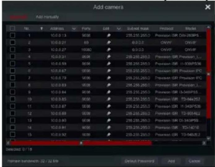
text_image
Add camera Add manually File Address Ports Edit Submit mask Protocol Model 1 10.0.0.13 9038 255.255.255.0 Provision ISR DM-280P5... 2 10.0.0.21 69 0.0.0.0 ONVF ONVF 3 10.0.0.27 16080 0.0.0.0 ONVF ONVF 4 10.0.0.31 9038 255.255.255.0 Provision ISR Provision_... 5 10.0.0.58 9038 255.255.255.0 Provision ISR II-340P536 6 10.0.0.67 9038 255.255.255.0 Provision ISR Provision IPC 7 10.0.0.79 9038 255.255.255.0 Provision ISR Provision IPC 8 10.0.0.83 9038 255.255.255.0 Provision ISR Provision_... 9 10.0.0.84 9038 255.255.255.0 Provision ISR I3-340P55... 10 10.0.0.85 9038 255.255.255.0 Provision ISR TD-944257 11 10.0.0.87 9038 255.255.255.0 Provision ISR I1-340P538 12 10.0.0.88 9038 255.255.255.0 Provision ISR TD-9554E2 13 10.0.0.90 9038 255.255.255.0 Provision ISR OI-340P58... 14 10.0.0.91 9038 255.255.255.0 Provision ISR TD-1401E 15 10.0.0.92 9038 255.255.255.0 Provision ISR TD-9482E2 Selected: D / T Name: Sandwidth: 32 / 32 Mb Default Password Add CancelEditing IP Address of Specific Camera
Must be done prior to adding the IPC. From the “Quick Add” interface, Click to edit the IP of a specific IP camera. Set the IP new IP address, subnet mask and default gateway. Input the IPC password and confirm. After a few seconds, the camera IP address will change.
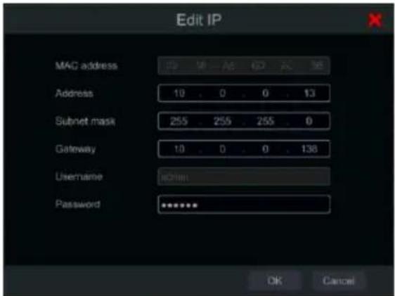
text_image
Edit IP MAC address Address 10 . 0 . 0 . 13 Subnet mask 255 . 255 . 255 . 0 Gateway 10 . 0 . 0 . 138 Username aOther Password ******** OK CancelEditing IP Address of Several Cameras
Must be done prior to adding the IPC. From the “Quick Add” interface, Click next to the “Edit” tab and choose “Batch IP Settings”. Choose the target cameras, set the first IP Address, Subnet Mask and Default Gateway and confirm. The IPC Addresses will be set in consecutive order. Make sure that all the target IP addresses are free (For example: If you configure 32 cameras and the starting IP is 192.168.1.1, then you need to make sure that all the addresses from 192.168.1.1 to 192.168.1.32 are free)
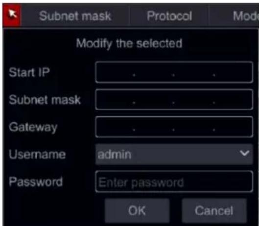
text_image
Subnet mask Protocol Mode Modify the selected Start IP Subnet mask Gateway Username admin Password Enter password OK CancelAdd Manually
IP Input: Input the IP address, port, username, password and protocol of the camera and click "Test" to confirm the settings are correct and that connection can be made with the camera.
Domain Input: If you are using DDNS to connect with the camera, click on the arrow next to the IP address to switch the connection mode from IP to domain.
Once finished, click the "Add" button.
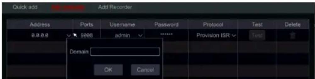
text_image
Quick add Add Recorder Address PortsUsername Password Protocol NepalDelete 8.8.8 9908 admin *****Provision ISR Domain OK CancelProtocol / RTSP Input: The system has several built-in communication protocols with the camera (Provision-ISR, ONVIF, Hikvision, Dahua). If you wish to add a channel using RTSP, click on the drop down menu arrow next to the chosen protocol (Default is “Provision-ISR”) and choose “Manage Protocol”. The following window will appear.
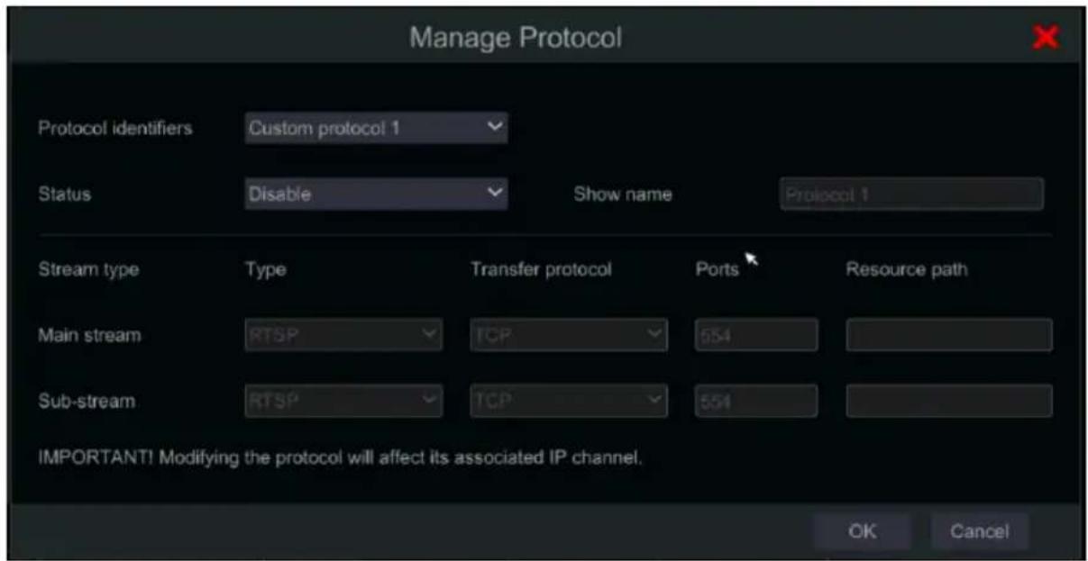
text_image
Manage Protocol Protocol identifiers Custom protocol 1 Status Disable Show name Protocol 1 Stream type Type Transfer protocol Ports Resource path Main stream RTSP TCP 554 Sub-stream RTSP TCP 554 IMPORTANT! Modifying the protocol will affect its associated IP channel. OK CancelSet a name for the protocol, enable it and set the values as required (Both master-stream and sub-stream values must be entered). Click OK to continue.
Add Recorder (Applicable only for NVRs)
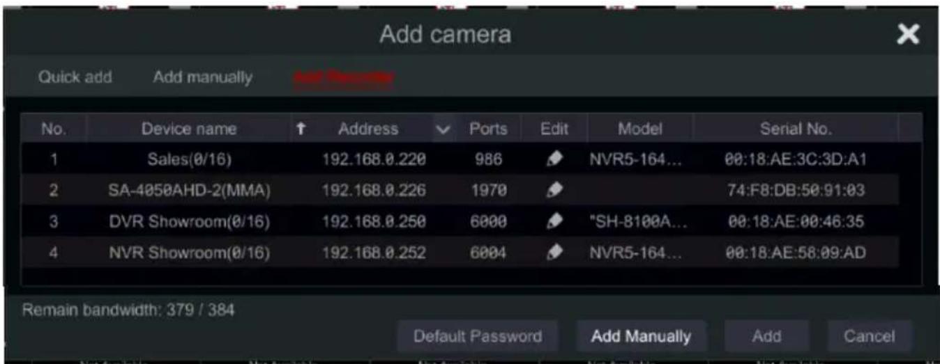
If you wish to view/record channels from another Provision-ISR device on the network you can use this option. Click on “Add Recorder”. The following window will appear.
text_image
Add camera Quick add Add manually Add Camera No. Device name ↑ Address ✓ Ports Edit Model Serial No. 1 Sales(0/16) 192.168.0.220 986 NVR5-164... 00:18:AE:3C:3D:A1 2 SA-4050AHD-2(MMA) 192.168.0.226 1970 74:F8:DB:50:91:03 3 DVR Showroom(0/16) 192.168.0.250 6000 "SH-8100A... 00:18:AE:00:46:35 4 NVR Showroom(0/16) 192.168.0.252 6004 NVR5-164... 00:18:AE:58:09:AD Remain bandwidth: 379 / 384 Default Password Add Manually Add CancelThe NVR will display automatically all the supported devices found on the LAN with its details. If you wish to add a channel from any of the displayed devices, double click on it and then double click on the channel you wish to add.
If you wish to add a channel from a recorder located on another network, click on “Add Manually” and input the IP address, port and login credentials for the device, then click on “Test Device” if the connection is well, you will get a list of available channels. Double click on the channel you wish to add.
Click 📄 to delete the camera. Click “Default Password” to set the default username and password per manufacturer.
4.2.2 Edit Camera's General Parameters
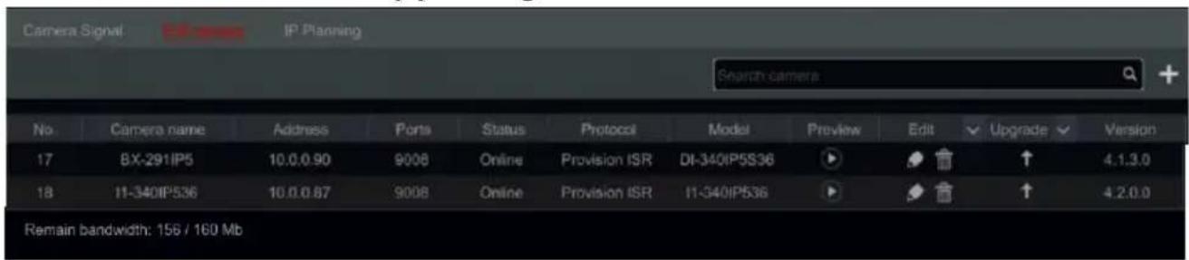
This can be done only when there are active video channels. You can use Preview button to trigger a live video stream from the camera in a pop up window for easy identification. Click “Edit Camera” in the setup panel to go to the edit interface.

text_image
Camera Signal IP Planning Search camera No Camera name Address Ports Status Protocol Model Preview Edit Upgrade Version 17 8X-291IP5 10.0.0.90 9008 Online Provision ISR DI-340IP5S36 ↑ 4.1.3.0 18 11-340IP536 10.0.0.87 9008 Online Provision ISR 11-340IP536 ↑ 4.2.0.0 Remain bandwidth: 156 / 160 MbEdit Camera's name: Click 📋 to edit the camera's name. Set the new name and confirm.
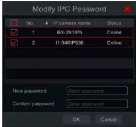
Change camera's password (for IP cameras only): Click on the button next to
“Operation” and then choose “Modify IPC Password”. In the opened window choose the desired cameras, input the new password and reenter it for confirmation.
text_image
Modify IPC Password No. ↓ IP camera name Status 1 BX-291IP5 Online 2 I1-340IP536 Online New password Enter password Confirm password Enter password OK CancelDelete Cameras (for IP cameras only): Click on 📄 to delete the camera.
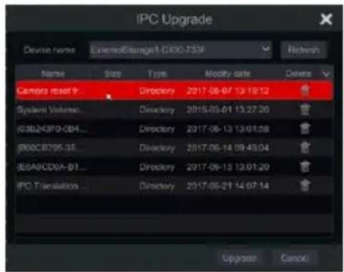
Update IPC Firmware (for IP cameras only): Click on to update the camera's firmware. After confirming the update, choose the cameras and firmware version from the opened window and confirm.
text_image
IPC Upgrade Device name ExternalTarget1-G300-733F Refresh Name Size Type Modify date Deires Camera reset # System Volume... Directory 2017-08-07 13:19:12 (638243F0-0B4... Directory 2017-08-13 13:01:58 (880CB795-35... Directory 2017-08-14 09:43:04 (85A9CD0A-B1... Directory 2017-08-13 13:01:20 IPC Translation... Directory 2017-08-21 14:07:14 Upgrade CancelNote:
If a PoE NVR is used, the IP cameras (with PoE function) which connect directly to the PoE port of the NVR will be displayed automatically in the camera list. The IP camera which occupies the PoE port has a prefix shown before its camera name. The prefix consists of PoE plus PoE port number. Cameras connected to PoE ports cannot be deleted from the camera list.
- IP cameras that connect directly to the PoE port of the NVR using “Provision-ISR” private protocol will be shown automatically in the camera list.
- One of the two conditions must be met for an IP camera that connect directly to the PoE port of the NVR using “ONVIF” protocol to be shown automatically in the camera list.
√ The IP camera is in the same network segment with the NVR internal ethernet port.
√ The DHCP (Assigning IP Address automatically) of the IP camera is enabled.
If the IP camera which connects to the PoE port cannot be displayed automatically in the camera list, please refer to Q6 in Appendix A FAQ for details.
4.3 “In-Channel Sequence” (Only Applicable for NVRs)
In channel sequence will run a sequence of specified cameras within a single window while in split mode. It can also be used on full screen, but will be less effective.
Add "In-Channel Sequence"
Click "In-Channel Sequence" in the interface to go to the configuration area as shown below.

text_image
Edit camera Group1 Dwell time ( 1 Min ) Number of cameras ( 2 ) Group2 Dwell time ( 1 Min ) Number of cameras ( 2 )Click to pop up the window as shown below. Set the group name and dwell time (the dwell time of the camera group sequence view) in the window. Check the cameras and click "Add" to add group. Click to view the cameras in the group after adding group.
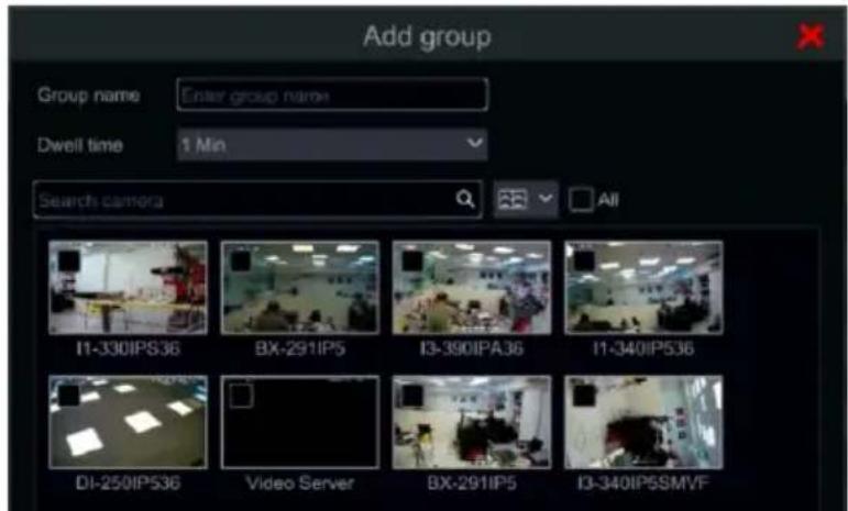
text_image
Add group Group name Enter group name Dwell time 1 Min Search camera All I1-330IPS36 BX-291IP5 I3-390IPA36 I1-340IP536 DI-250IP536 Video Server BX-291IP5 I3-340IP5SMVF4.3.1 Edit In-Channel Sequence
Click to modify the group information such as group name and dwell time. Click to delete the group.

4.4 IPC Networking (Applicable only for NVRs and Hybrid DVR models)
IPC networking will allow you to remotely configure IP cameras and basic network parameters of other devices. This is applicable only for devices running Ossia v1.1 and up. Below you will be able to learn about the different options of this feature.
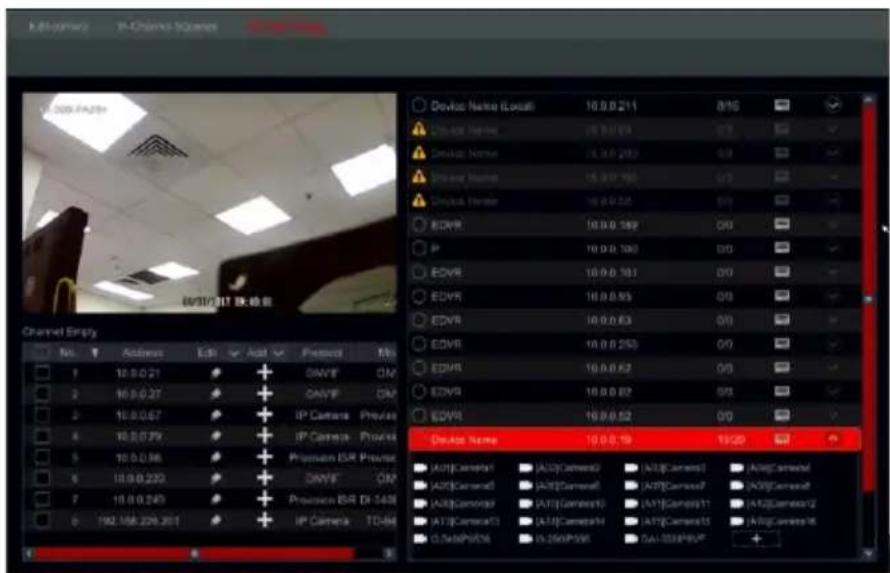
text_image
Device Nets (Local) 10.0.0.211 8/16 Device Name: 10.0.0.213 0/3 Device Name: 10.0.0.283 0/3 Device Name: 10.0.0.285 0/3 Device Name: 10.0.0.288 0/3 EDVR 10.0.0.189 0/3 P 10.0.0.190 0/3 ECVR 10.0.0.191 0/3 EDVR 10.0.0.95 0/3 EDVR 10.0.0.63 0/3 EDVR 10.0.0.253 0/3 EDVR 10.0.0.62 0/3 EDVR 10.0.0.62 0/3 Device Name: 10.0.0.19 19/20 AutoCamera1 | AutoCamera2 | AutoCamera3 | AutoCamera4 AutoCamera5 | AutoCamera6 | AutoCamera7 | AutoCamera8 AutoCamera9 | AutoCamera10 | AutoCamera11 | AutoCamera12 AutoCamera13 | AutoCamera14 | AutoCamera15 | AutoCamera16 DataPhoto | DataPhotoID | DataPhotoID | DataPhotoID | +4.4.1 IP Camera management
The IP Camera management is identical to the “Add/edit camera” Interface. You can set the IP parameters and the name of the camera through it. Please refer to section 4.2 Add/Edit Camera for more information.
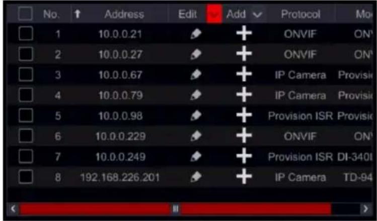
text_image
No. ↑ Address Edit Add Protocol Mo 1 10.0.0.21 + ONVIF ON¹ 2 10.0.0.27 + ONVIF ON¹ 3 10.0.0.67 + IP Camera Provisi 4 10.0.0.79 + IP Camera Provisi 5 10.0.0.98 + Provision ISR Provisi 6 10.0.0.229 + ONVIF ON¹ 7 10.0.0.249 + Provision ISR DI-340I 8 192.168.226.201 + IP Camera TD-944.4.2 Device Management
Here you will be able to remotely set the general network parameters of the device and configure the IPC cameras connected to the device. The following information is available: Device name, Device current IP Address, Cameras and availability.
Clicking on will open the device menu You will have the following options:
- Edit IP – Set the device's IP address, subnet mask and gateway.
Tick the devices you wish to configure and set the start IP address. The device will set automatically the rest of the IP address. Make sure that the whole segment is available before running this procedure.
Set the subnet mask and gateway - this will be set for all devices.
Set the username and password for the devices. If any of the devices have a different password, it should be set independently otherwise the procedure will fail.
Click OK to start the process.
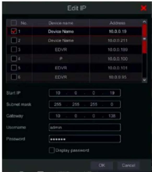
text_image
Edit IP No. Device name Address 1 Device Name 10.0.0.19 2 Device Name 10.0.0.211 3 EDVR 10.0.0.189 4 P 10.0.0.100 5 EDVR 10.0.0.101 6 EDVR 10.0.0.95 Start IP 10 . 0 . 0 . 19 Subnet mask 255 . 255 . 255 . 0 Gateway 10 . 0 . 0 . 138 Username admin Password ****** Display password OK Cancel- Edit user – set the admin address for the specified device. This is only required if the device password is different than the default password (admin / 123456).
Tick all the relevant devices and set the user name and password
- Buzzer – the buzzer will help you identifying the device you wish to configure by activating the buzzer on the unit itself.
- Delete all – will delete all IP cameras set on the device.
Click on ☑ to open a list of all cameras connected to the device. Click on ⚠️ to hide it. Once the list is open, you can delete specific IP cameras by pointing on it and clicking on the

icon that appears. To add a specific camera to the device, choose the device and add cameras from the IPC interface on the left. Make sure that you set the user credentials beforehand.
5 Live-view Introduction:
5.1 Live-View Interfaces:
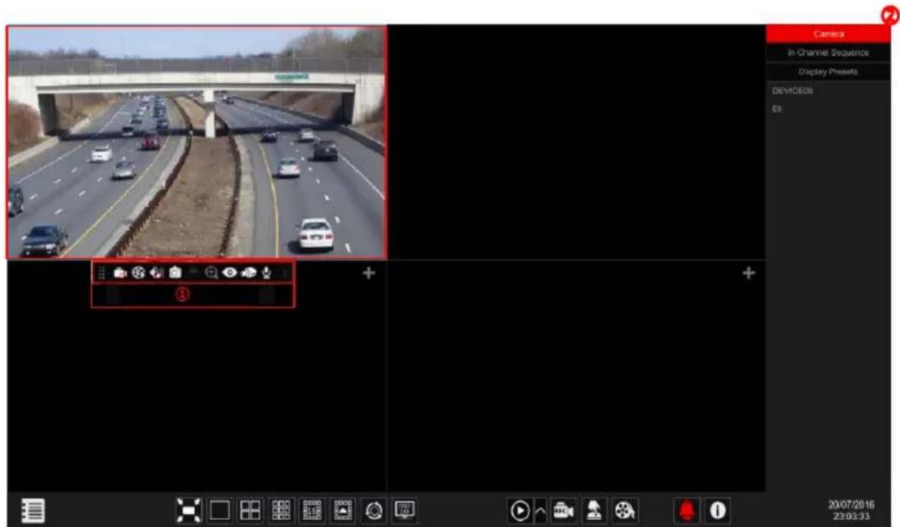
You must have active video channels for this interface to be active (see 4.1.1 Add Camera for details). Refer to the inter face as shown below to learn about the live view interface.
text_image
Camera In Channel Sequence Display Presents DEVICE05 E: 20/07/2016 23:03:33Live view indicators (Will appear only when a channel is active)
| Indicator | Meaning | |
 | Active Motion detection | |
 | Active Analytics detection | |
 | Motion Recording On | |
 | Schedule Recording | |
 | Sensor Recording | |
 | Manual Recording | |
 | Analytics Recording | |
 | Indicating that the channel support PTZ operations | |
 | Indication that the audio stream for the channel is enabled | |
Click on the live-view window to show the channel tool bar as shown in area ①. Right click on the preview window to show the channel menu list. The tool bar and menu list are explained in the table below.
| Button | Menu List | Meaning |
 | -- | Move tool. Click and drag it to move the tool bar. |
 | Manual Record On | Start/Stop manual recording for the specific channel. |
 | Instant Playback | Start Instant playback for the specified channel. The playback will commence within the selected window. See 8.1 Instant Playback for details. |
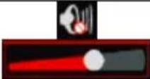 | Enable Audio + Volume Control | Enable/disable audio from the selected cannel (Requires camera/channel to support of this feature). Once enabled, a volume slider will appear to control the output volume. |
 | Snap | Take a snapshot and open a snapshot pop-up. Click “Save” in the window to save the image. Click “Export” to export the image. |
 | PTZ Control | Switch to the PTZ control interface. See Chapter 6 PTZ for details. |
 | Zoom In | Switch to the digital zoom interface. Digital Zoom can also be achieved by placing the mouse cursor on the required object and using the mouse scroll wheel to zoom in & out. |
 | Fish Eye | Open Fish-Eye display controls. Refer to 5.2 Fish-Eye Display |
 | -- | Switch to the image adjustment interface. Refer to 5.3.4 Image Adjustment for details. |
 | -- | Open audio out (Talk) |
 | Face Recognition | Supporting Devices Only will display the face recognition interface button. If the camera doesn’t support face detection, this icon will be grey. |
| -- | Camera Info | View the camera information. |
5.2 Fish-Eye Display:
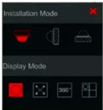
Fish eye cameras are usually installed to cover large areas and provide a 360^ view. In order to dewarp the image properly, you need to set the installation method and the view you wish to get.
Click on the "Fish Eye" Icon to get the following pop up:
Choose the installation mode out of Ceiling, Wall and Desktop. Setting the installation mode wrong will result in wrong view of the video.
Now choose the display mode out of the following:
1) Fish-Eye: Normal view of the warped fish eye sphere view.
2) Panorama: A stretched view of the sphere removing all the black borders.
3) 360^ view: See 2 180^ views side by side
4) Fish-Eye + 3PTZ: Normal view of the warped fish eye sphere view + 3 Digital PTZ that can be dragged and moved using the mouse.
text_image
Installation Mode Display Mode5.3 Live View Digital Zoom:
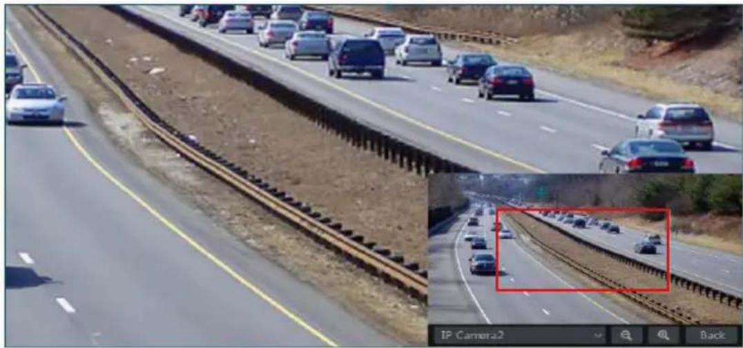
Digital Zoom can be achieved by one of two methods: The first and more intuitive one is the mouse scroll wheel. Just left click on the channel you wish to control, point the mouse cursor on the object you want to zoom on and scroll the mouse wheel up or down to zoom in or out. The second method is by the digital zoom interface. The digital zoom interface is shown below. Press and drag the red box to select the zoom area. Click / to zoom the image. Click the camera selection box to select other cameras for amplification. Click “Back” to return to the live preview interface.
natural_image
Highway traffic scene with multiple lanes and cars, inset shows a close-up of a red box highlighting a specific lane (no text or symbols visible)5.4 Live-View Modes:
5.4.1 Display Modes Tabs
The system offers several display modes. In the latest version, the only available tab is “Camera” by default. If you wish to edit the view option tabs, click on the “☐” button at the top right corner of the screen and choose which tabs you wish to activate/disactivate.
5.4.2 Customized Display Mode
Set different screen split modes and camera layouts as required and save the display to create a preset. Refer to the picture below. Double click on the display preset from the list to activate it.
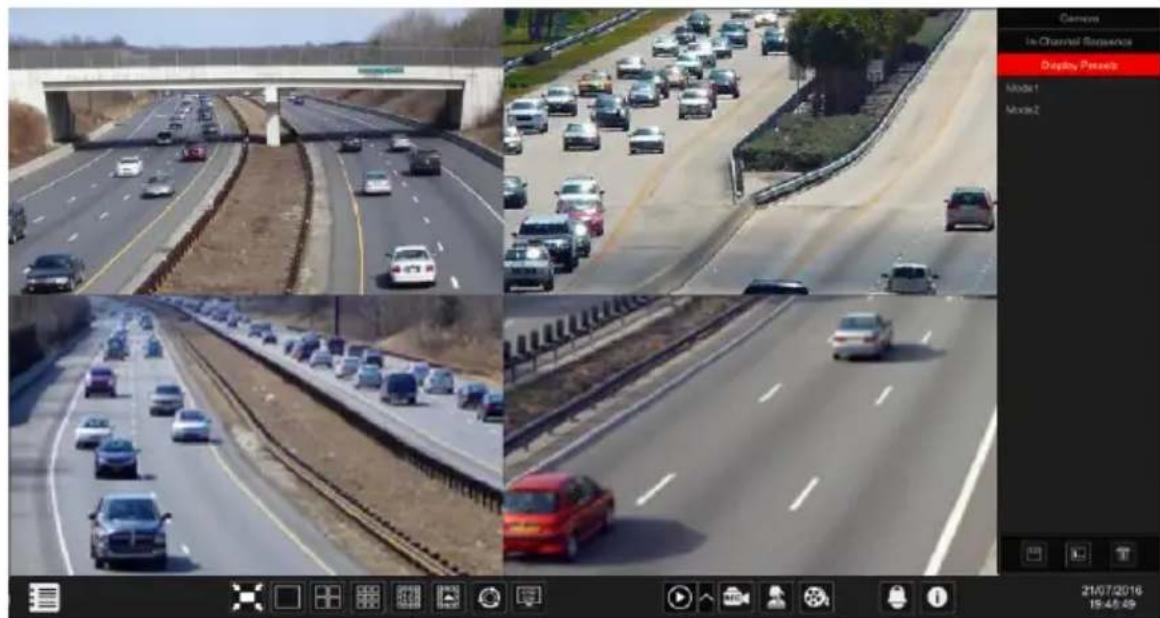
text_image
Camers In Channel Sequence Display Passes Model 1 Model 2 21/07/2016 15:45:49➢ Add Customized Display:
Method One:
① Click "Customized Display Modes" in the main interface
② Set the screen split mode.
③ Add and organize the cameras as desired.
④ Click the "Save" button under the display presets list
⑤ Enter the display preset name in the popup window and click "OK" to save it.
Method Two:
④ Click Start→Settings→System→Basic→Layout Settings
⑤ Click + to add a new layout.
⑥ Choose the screen split mode from the bottom.
⑦ Double click the camera or camera group in the list to add them to the selected window.
⑧ Click ★ to save the defined output as a preset (refer to 5.2.4 Scheme View In Sequence for detailed configurations). The saved preset will be displayed in the display preset list in the live-view interface.
Using method two will affect the sequence settings - please refer to 5.3.2 Sequence for additional information.
➢ Edit Customized Displays
Click “Customized Display” tab in the live-view interface. Select the required display from the list. Click “Rename” to edit the display mode name; click “Delete” to delete the display mode.
5.4.3 Sequence
The sequence view will automatically switch between cameras in specified times.
If a customized scheme has not been created, it will keep the split layout and go through all of the available cameras. If the scheme has been created – the sequence will run through the created scheme. Controlling the sequence will be done from the sequence control icon as shown below.

text_image
"Running Sequence" Icon Sequence Control➢ Sequence Scheme Settings
Click Start→Settings→System→Basic→Layout Settings to go to the interface as shown below. Area ① displays all the schemes; area shows the camera layout; area ③ displays all the cameras and groups; area ④ is the tool bar (☐: clear button; ★: favorite button, click it to save the layout as preset).
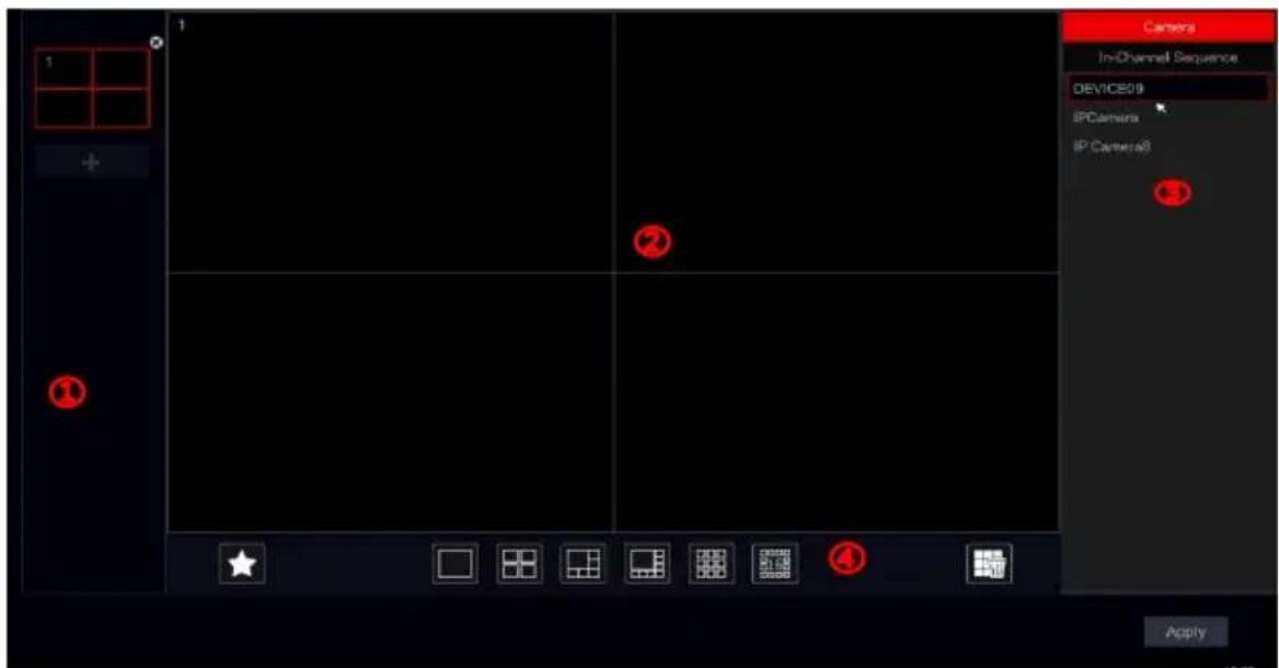
text_image
Camera In-Channel Sequence DEVICE09 IPCamera IP Camera8 ApplyAdd Scheme
Click + in area ① to create a new scheme. Click ✗ on the top right corner of the scheme to delete it.
Configure Scheme
a) Select a scheme in area ① and the screen split mode button from area ④.
b) Drag cameras from the camera list to the desired window in area ②. The camera or group will be added into the selected window.
c) You can click the right-click on a camera and click "Clear" to remove a single camera or click to remove all the cameras.
d) Click "Apply" to save the settings.
➢ Start Sequence View
Go to the live-view interface and click 📋 to pop up a little window. Set the dwell time for each window and click 🔒 to start the sequence. Double click the sequence view interface to pause the view; double click again to restore the view. Click 🔒 to stop the view.
5.4.4 In Channel Sequence (Applicable for NVRs only).
You can start “In-Channel Sequence” only if a camera group was created. (See 4.2.1 Add “In-Channel Sequence” for details).
① Go to the live-view interface and select a camera window.
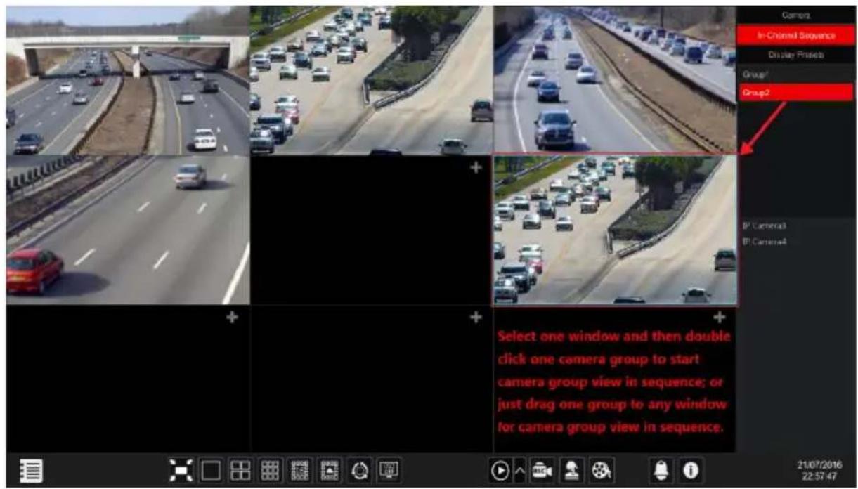
text_image
Camera In-Channel Sequence Display Protocols Group1 Group2 B/ Camera3 B/ Camera4 Select one window and then double click one camera group to start camera group view in sequence; or just drag one group to any window for camera group view in sequence. 21/07/2016 22:57:47② Double click one the “In-channel Sequence” group on the right side of the interface. The cameras in the group will start sequencing one by one in the selected camera window.
③ You can also drag the group directly to any preview window.
④ Right click on the view window and click "Close Dwell" button to stop the sequence.
5.4.5 Face Recognition (Applicable for Face Recognition NVRs only).
The Face recognition tab will open the face recognition display for all face detection cameras
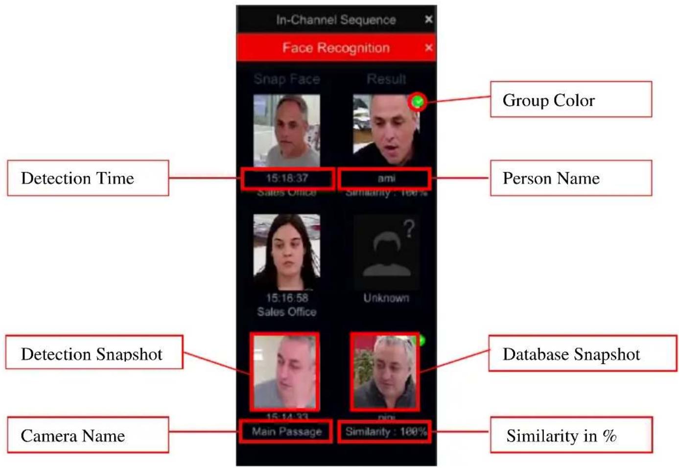
text_image
In-Channel Sequence Face Recognition Snap Face Result Group Color Detection Time 15:18:37 ami Person Name Sales Office Similarity : 100 % 15:16:58 Unknown Detection Snapshot Main Passage Database Snapshot Camera Name Similarity in %configured on the system. The pane and its controls are as follows:
5.4.6 Controls and settings:
The face recognition has 2 important settings that can be configured from the face recognition pane:
1) Similarity: Similarity means the certainty of the system that the recognized face is correct. For example: 100% Similarity means that the system is 100% sure that the recognized person is correct.
text_image
Similarity : 75%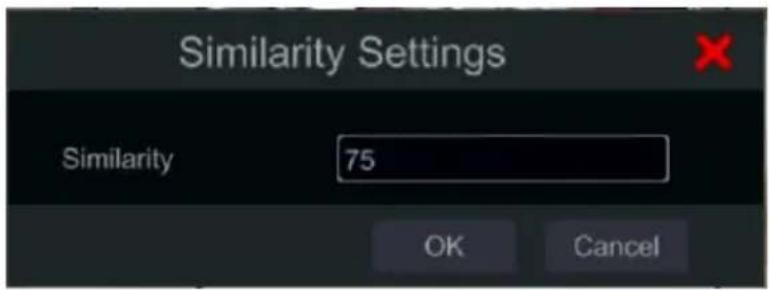
text_image
Similarity Settings Similarity 75 OK Cancel2) Enable Face Tracking Box: a cosmetic addition to see the identified face on the live image in real-time. This setting has no effect on the face recognition capabilities and it will work with this option enables or disabled.
text_image
Settings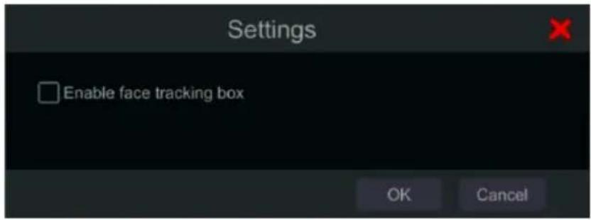
text_image
Settings Enable face tracking box OK CancelFace recognition interface controls:
| Button | Menu List Meaning |
 | Add to Database: Add a person to the database |
 | Search: Search for the person in the past day |
 | Instant Playback: Playback the detection moment |
 | General Info: Get the detection info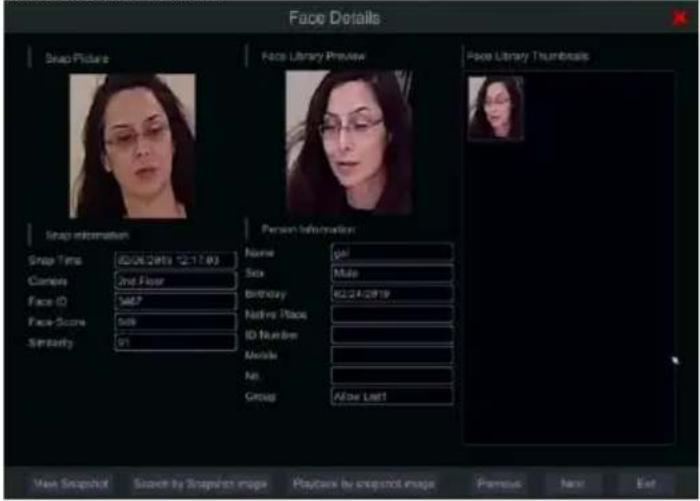 |
5.5 Emergency Live-View:
In some cases you will have to go back to the live-view interface as soon as possible. Doesn't matter where you are in the system or what you are currently doing. The “Emergency Live-View” was designed just for that.
From any place in the system, click on the middle mouse button to activate the “Emergency Live-View”. This will take you back to the last live view display you were viewing.
Please note: Using the “Emergency Live-View” during configuration will exit the configuration window and discard any unsaved changed you have made.
5.6 Image Configuration
5.6.1 OSD Settings
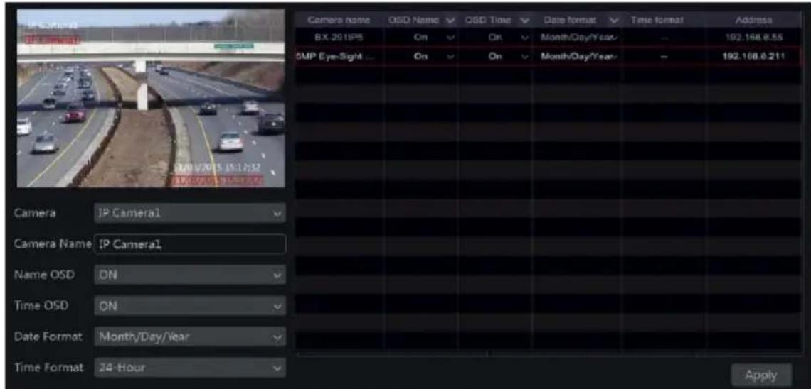
Click Start→Settings→Camera→Image→OSD Settings to go to the interface shown below. Select the camera, input the camera name (or double click the camera name in the camera list to edit the camera's name), enable or disable the name and time OSD (if enabled, drag the red name and time OSDs in the image view area to change the OSDs' display position) and select the date and time formats. Click “Apply” to save the settings.
text_image
Camera name OSO Name QSO Time Date format Time format Address BX-2018PS On On Month/Day/Year - 192.168.8.55 SMP Eye-Sight On On Month/Day/Year - 192.168.8.211 Camera IP Camera1 Camera Name IP Camera1 Name OSD DN Time OSD ON Date Format Month/Day/Year Time Format 24-Hour Apply5.6.2 Image Settings (Setting Interface)
Click Start→Settings→Camera→Image→Image Settings.
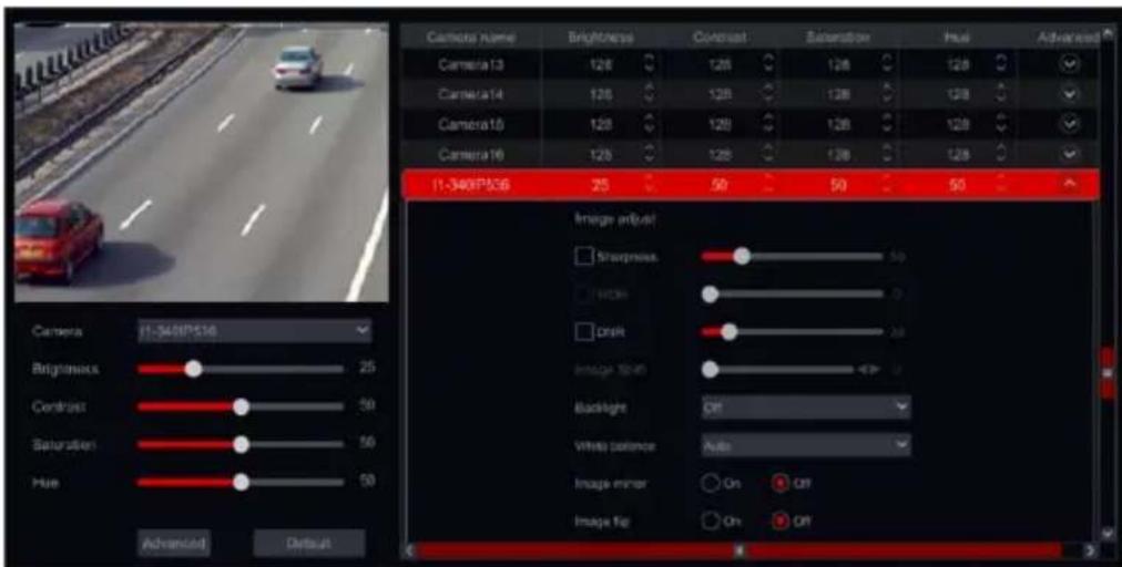
Select the camera and set the image brightness, contrast, saturation and hue. For advanced settings you click on the arrow under the “Advanced” tab. Only cameras connected by “Provision-ISR” protocol will support advanced features.
You can click "Default" button to restore the image settings to the default factory settings.
text_image
Camera name Brightness Contrast Saturation Hue Camera 13 128 128 128 128 Camera 14 128 128 128 Camera 15 128 128 128 Camera 16 128 128 128 1-340FP506 25 50 50 50 Camera Brightness Sharpness 50 Contrast OK On On Image Adjust Image Speed 400 Backlight Off White balance Auto Image mirror On Off Image Top On OffNote: Different IP Cameras will support different Image configuration features.
5.6.3 Mask Settings
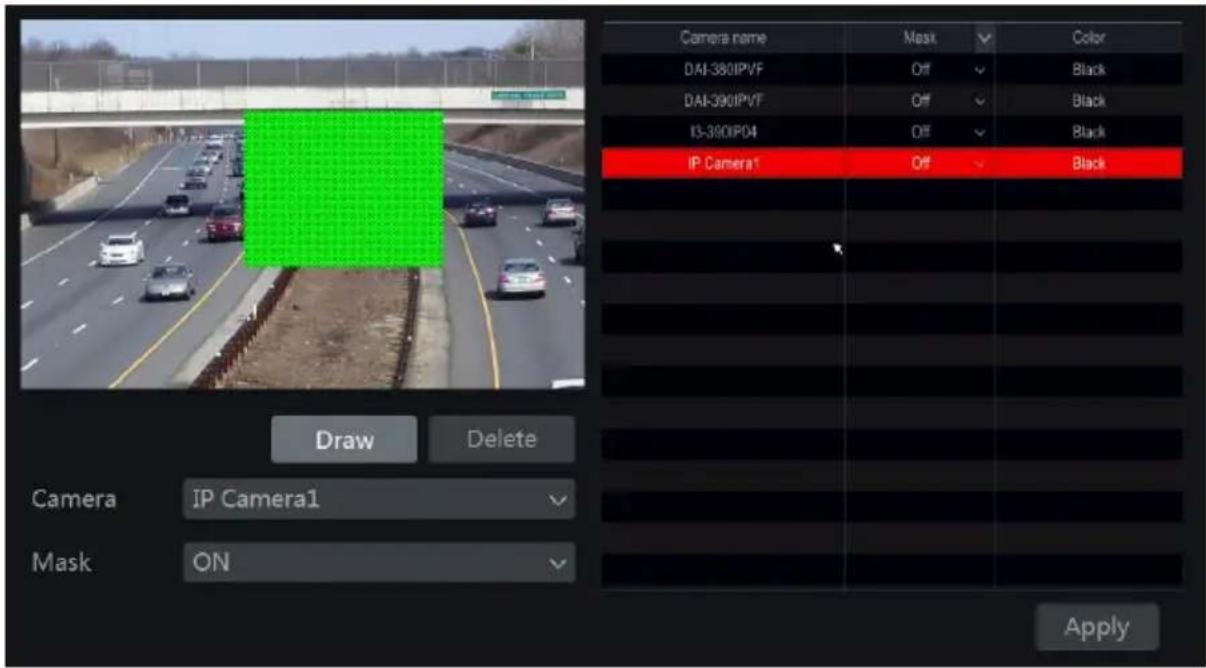
Some areas of the image can be masked for privacy. Up to four mask areas can be set for each camera. (Only for Provision-ISR Cameras non-ONVIF cameras).
Click Start→Settings→Camera→Image→Mask Settings to open the interface as shown below. Select the camera and enable the mask. Click “Draw” button and drag the mouse on the image area to set the mask area; click “Delete” button to delete the mask areas; click “Apply” to save the settings.
text_image
Camera name Mask Color DAI-380IPVF Off Black DAI-390IPVF Off Black I3-390IPD4 Off Black IP Camera1 Off Black Draw Delete Camera IP Camera1 Mask ON Apply5.6.4 Water Mark Settings (Applicable for DVRs only)
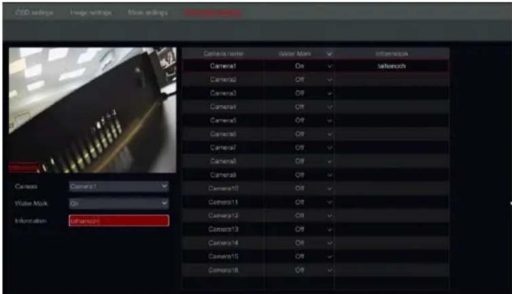
Water marks are used to identify a recorded clip and reduce the probability that it has been tampered with. The Water mark will be added on top of the video clip and it can be removed while playing back and even while watching a “.dat” file backup using the RSAP player.
To configure the water-mark, please follow the following steps:
1) Click Start→Settings→Camera→Image→Water Mark.
2) Choose the channel you wish to set.
3) Set "Water mark" to "On".
4) Input the text you wish to appear as watermark. (Up to 15 characters. Only letters and numbers are allowed) and confirm.
5) Click "Apply" to save the settings.
text_image
CSP settings Image settings Main settings Main settings Camera name Water Mask Information Camera1 On Water Mask Camera2 Off Camera3 Off Camera4 Off Camera5 Off Camera6 Off Camera7 Off Camera8 Off Camera9 Off Camera10 Off Camera11 Off Camera12 Off Camera13 Off Camera14 Off Camera15 Off Camera16 OffWhen playing back the specified camera, you will be able to enable/disable the water mark from showing.
Watermark Disabled

text_image
06/08/2017 09:41:17Watermark Enabled

text_image
tathanoch 06/08/2017 09:41:185.6.5 Fish-Eye (Applicable for Supporting NVRs only)
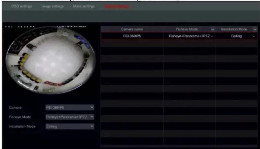
Fish-Eye Settings will allow you to set the installation way of the fish-eye camera in order to get the proper dewarping.
1) Click Start→Settings→Camera→Image→Fish Eye.
text_image
OSO settings Image settings Mass settings Photo series FEI-368IP5 (0/00/2018 15:39:01) Camera name Fisheye Mode Installation Mode FEI-368IP5 Fisheye+Panorama+3PTZ Ceiling Camera FEI-368IP5 Fisheye Mode Fisheye+Panorama+3PTZ Installation Mode CeilingHere you can set the installation mode and your preferred view mode. Make sure that the installation mode is set properly for the image to be displayed correctly.
5.6.6 Image Adjustment (Live-View Interface)
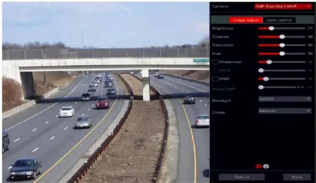
Go to live-view interface. Choose the channel by clicking on the desired and click on button from the tool bar under the camera window to switch to the image adjustment interface.
text_image
Camera SMP Eye-Sight MVF Image adjust Lens control Brightness 25 Contrast 50 Saturation 50 Hue 50 Sharpness 100 WDR 0 DNR 100 Image Shift 0 Backlight HWDR Grade Medium Default BackImage Adjustment
Drag the slider to set the image brightness, contrast, saturation and hue values. Check Sharpness, WDR and DNR to enable it and drag the slider to set their values. Click “Default” button to set these parameters to their default values.
The introductions of these parameters are as follows:
| Parameter | Meaning |
| Brightness | Image brightness level |
| Contrast | The color difference between the brightest and darkest parts. |
| Saturation | The intensity of colors, expressed as the degree to which it differs from white. |
| Hue | Color levels of the image. |
| Sharpness | Relates to the sharpness level of the image and the image edges. |
| WDR | WDR (Wide Dynamic Range) function helps the camera provide clear images even under extreme light conditions. When there are both bright and dark areas in the field of view, WDR balances the brightness level of the whole image and provide clearer image. |
| DNR | DNR (Digital Noise Reduction): decreases the noise levels and making the image smoother. Increasing the value will increase the noise reduction but it will reduce the image resolution and details. |
Notes:
1) Different IP Cameras will support different Image configuration features.
2) Some cameras have more than one settings page. You need to switch pages in the bottom of the image adjustment area.
| Parameter | Meaning |
| White Balance | Automatically adjust the color temperature according to the environment. Can also be set manually. |
| Image Mirror | Mirror the video image right and left. |
| Image Flip | Flip the video image upside down. |
➢ Lens Control (IP Cameras only. Must be supported by the camera – MVF Model):
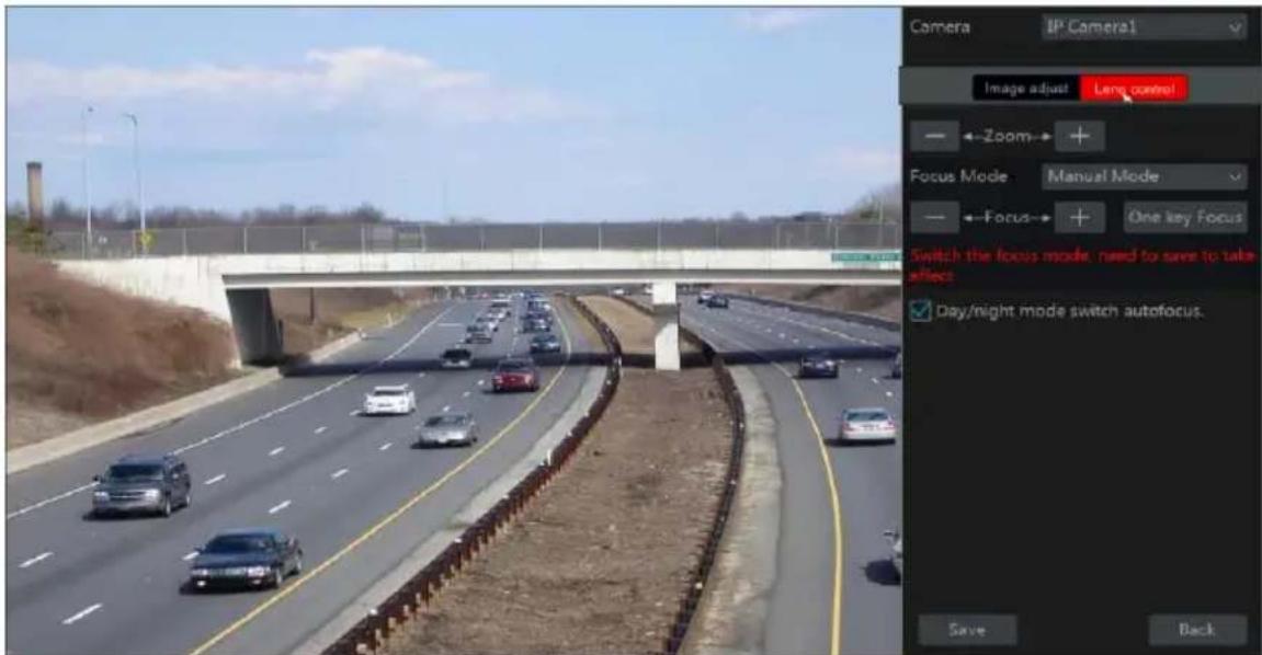
Select the camera and click “Lens Control” to go to lens control tab. Click - or + to adjust the zoom and focus parameters of the camera’s lens. Click “Save” to save the settings.
text_image
Camera IP Camera1 Image adjust Lens control → Zoom → + Focus Mode Manual Mode → Focus → + One key Focus Switch the focus mode, need to save to take effect Day/night mode switch autofocus. Save BackThe introductions of these parameters and buttons are as follows:
| Button/Parameter | Meaning |
 | Click  n/out. n/out. |
| Focus Mode | If manual mode is selected, focus button, “One Key Focus” and “Day/night mode switch autofocus” will be available; If auto mode is selected, the time interval setup will be available. |
 | Click  to increase/decrease the focal length. to increase/decrease the focal length. |
| One key Focus | Instant Focus |
| Re-focus when camera switches between day/night | If checked, the lens will focus automatically when the camera switches between day/night modes. |
Note: This function is only available for the models with motorized VF (MVF) lens.
6 PTZ
6.1 PTZ Control Interface:
The device supports full control over dome or PTZ cameras (Via CoC/RS-485 for all types of DVRs and via private or ONVIF Protocol for NVRs and Hybrid DVRs only.
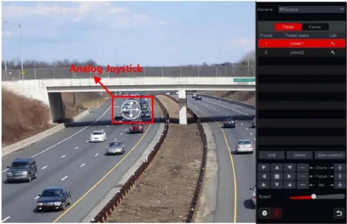
Click on the desired camera and on the icon from the channel tool bar. The live view will switch to the PTZ control interface as shown below. You can select another IP dome or PTZ from the dropdown menu on the top right of the PTZ interface.
text_image
Analog Joystick Camera PCamera Preset Cnuse Preset Preset name Call 1 preset1 2 preset2 Add Delete Save position Zoom Focus Info ScrewIntroductions of the interface buttons:
| Button | Meaning |
 |  to rotate the dome. Click to stop rotating the dome. to rotate the dome. Click to stop rotating the dome. |
 |  to zoom in / out. to zoom in / out. |
 |  to increase / decrease the focal length. to increase / decrease the focal length. |
 |  to increase / decrease the aperture. to increase / decrease the aperture. |
 | Drag the slider to adjust the movement speed. |
 |  to start / stop manual recording. to start / stop manual recording. |
 |  hide / show the analog joystick. hide / show the analog joystick. |
 | Return to the live view interface. |
▶ Analog Joystick Control
1) The analog joystick on the left side of the interface provides quick PTZ control. The dome or PTZ will move when you drag the analog joystick. The further you drag the analog joystick from the middle of the image, the faster the dome or PTZ will move. The dome or PTZ will stop rotating when you release the analog joystick or move it to the middle.
2) Click and hold the left mouse button to zoom in
3) Click and hold the right mouse button to zoom out
➢ Preset Settings
Presets can be used to save important locations and recalling it quickly when needed.
As default, the preset list is empty so you will have to add and configure the presets that are important to you.
1) Click "Preset" to go to preset operation tab and click "Add" button to pop up a setting window as shown below. Select the desired preset number and input the preset name. Click "OK" to save the settings.
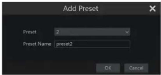
text_image
Add Preset Preset 2 Preset Name preset2 OK Cancel2) Adjust the camera direction and click "Save
Position" to save the current preset position on the selected preset. You can also go to preset setting interface for preset setting, see 6.2 Preset Setting for details.
3) Click 📄 in the preset list to call the preset; click "Delete" button to delete the selected preset.
4) You can add up to 255 presets for each supported camera.
Cruise Settings
Cruises are built from a sequence of presets and are used for creating a specified patrol between presets for an endless duration (Cruise will run until you will stop it, or move the camera). Therefore, you must save the desired presets before creating a cruise.
1) Click “Cruise” to go to cruise operation tab and click “Add” button to open the settings window as shown on the right.
2) Input the cruise name and click "Add preset" to pop up the "Add Preset" window as shown above on the right.
3) Select the preset name, dwell time and preset speed and click "OK".
4) In the "Add Cruise" window, you can click

to redefine the checkpoint. Click to
delete the preset.
5) Click "Add" button to save the cruise.
6) You can also go to cruise setting interface for cruise setting, see 6.3 Cruise Setting for details.
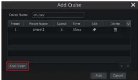
text_image
Add Cruise Cruise Name cruise2 Preset Preset Name Speed Time Edit Delete 1 preset1 $ SSSex Add Preset Add Cancel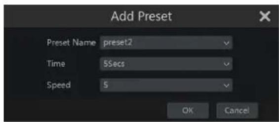
text_image
Add Preset Preset Name preset2 Time 5Secs Speed 5 OK Cancel7) You can add 8 cruises for each dome at most.
In order to activate the cruise, click ▶ to start the cruise and click □ to stop the cruise. Any movement or other command sent to the camera from the PTZ interface will stop the cruise as well.
Click "Delete" button to delete the selected cruise.
6.2 Preset Settings
Click Start→Settings→Camera→PTZ→Preset to go to the interface as shown below.
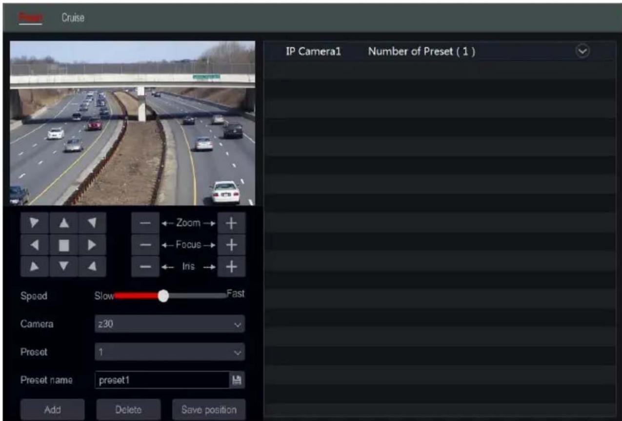
text_image
Cruise IP Camera1 Number of Preset ( 1 ) Zoom Focus Iris Speed Slow Fast Camera z30 Preset 1 Preset name preset1 Add Delete Save position▶ Add preset
Select the desired camera and click “Add” button to add preset; or click in the camera list on the right side of the interface to display the preset information of the camera and click to add preset. The operations of the “Add Preset” window are similar to that of the PTZ control interface; please see 6.1 PTZ Control Interface Introduction for details.
Edit preset
Select camera and preset. You can input the new name of the preset and click 📄 to save the new preset name. Adjust the rotating speed, position, zoom, focus and iris of the preset and click “Save Position” to save the preset.
Delete Preset
Select camera and preset and click "Delete" to delete the preset.
Cruise Setting
Click Start→Settings→Camera→PTZ→Cruise to go to the interface shown below.
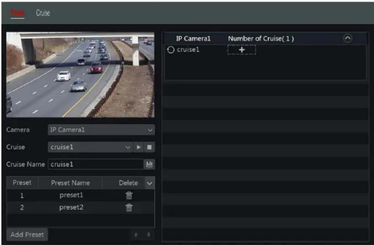
text_image
Cruise IP Camera1 Number of Cruise( 1 ) cruise1 Camera IP Camera1 Cruise cruise1 Cruise Name cruise1 Preset Preset Name Delete 1 preset1 2 preset2 Add PresetAdd Cruise
Click the camera list on the right side of the interface to display the cruise information of the camera and click + to add cruise. The operations of the “Add Cruise” window are similar to that of the PTZ control interface; please see 6.1 PTZ Control Interface Introduction for details.
Edit Cruise
Select the camera and cruise in the “Cruise” interface. Input the new cruise name and click to save the cruise name. Click “Add Preset” to add preset to the cruise. Click to delete the preset from the cruise. Click a preset in the preset list and click to move the preset down the list and click to move the preset up the list. Click to start the cruise and click to stop it.
Delete Cruise
Click the camera list on the right side of the interface to display the cruise information of the dome and click the top right corner of the cruise to delete it.
7 Record & Disk Management
7.1 Record Configuration:
7.1.1 Mode Configuration:
Please format the HDDs to enable recording (refer to 7.5 Disk Management for details).
The Ossia recording interface was redesigned to be clearer and easier to configure. It is based on statistics showing that most users configure the recording to work all year long in 24x7 schedule – the “Auto” mode is the best choice for these users. “Manual” mode is for users who wish to customize the recording/schedule configuration.
Click Start→Settings→Record→Mode Settings to go to the mode settings interface.
➢ Auto Mode: The standard setting will include the following presets:
Motion Record: Record will start upon Motion Alarm under 24x7 schedule for all channels.
Sensor Record: Record will start upon Sensor Alarm under 24x7 schedule for all sensors.
Motion Record + Sensor Record: Record will start upon Motion or Sensor Alarms under 24x7 schedule for all channels and sensors.
Always (24 x7) Record + Motion Record: All the channels will be recorded continuously. Motion alarms will be marked in the event list and trigger "Event Record".
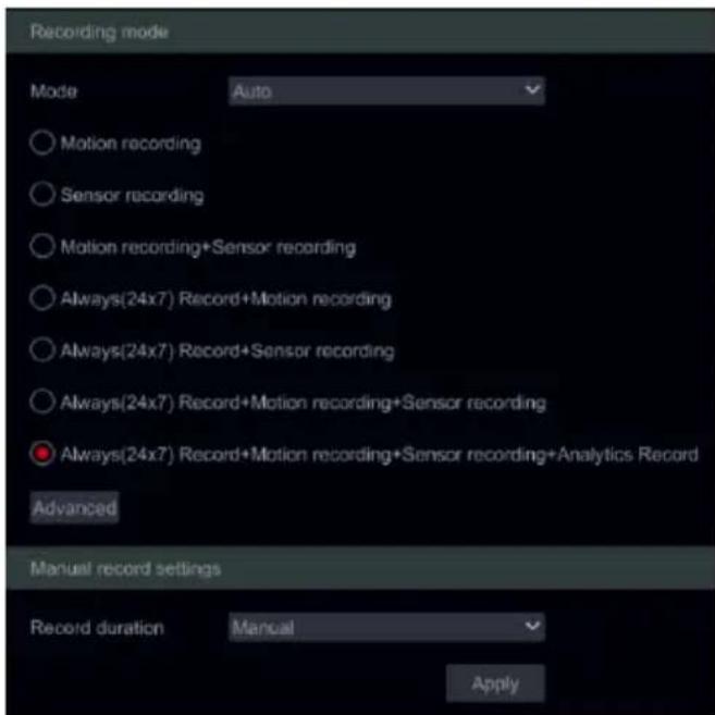
text_image
Recording mode Mode Auto Motion recording Sensor recording Motion recording+Sensor recording Always(24x7) Record+Motion recording Always(24x7) Record+Sensor recording Always(24x7) Record+Motion recording+Sensor recording Always(24x7) Record+Motion recording+Sensor recording+Analytics Record Advanced Manual record settings Record duration Manual ApplyAlways (24×7) Record + Sensor Record: All the channels will be recorded continuously. Sensor alarms will be marked in the event list and trigger “Event Record”.
Always (24 ×7) Record + Motion Record + Sensor Record: All the channels will be recorded continuously. Motion and sensor alarms will be marked in the event list and trigger “Event Record”.
Always (24 x7) Record + Motion Record + Sensor Record + Analytics Record: All the channels will be recorded continuously. Motion, sensor and analytics alarms will be marked in the event list and trigger “Event Record”.
If you wish to create a personalized combination, click on the “advanced button to open the advanced menu: The advanced menu allows you to create any combination you require (As long as it is not currently available in the standard menu). Tick the recording triggers you wish for the combination to have and click on “add” to continue. The new combination will be added as a new line to the standard menu. Only one customized combination can be used. If you wish to edit it, click on the advanced button once again and change the selected triggers.
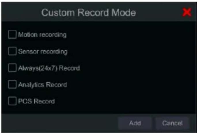
text_image
Custom Record Mode Motion recording Sensor recording Always(24x7) Record Analytics Record POS Record Add CancelSelecting one of the auto modes will pop up the stream settings window as shown below. Set the video encode type, resolution, FPS, bit-rate type, bitrate and audio for each of the camera and click “OK” to save the settings. It is recommended to follow the bit-rate recommended by the system in the “Bit-Rate Limit Recommended Range” Tab.
Important: In case you chose one of the continuous modes, make sure to configure both “Normal” and “Event” settings.

text_image
Always(24x7) Record+Motion recording+Sensor recording Motion recording+Sensor recording Camera name Stream type Encode GOP Resolution FPS Bitrate Type Quality Bitrate Recommended Bitrate Range Audio BX-251IP5 Main stream H.265 188 1928x1888 25 VBR Higher 2848Kbps 4288~7146Kbps On 5MP Eye-Sight ... Main stream H.265 80 2592x1944 20 VBR Higher 4896Kbps 8576~14253Kbps On FEI-368IP5 Main stream H.265 160 2168x2168 25 VBR Higher 3872Kbps 9862~16437Kbps OnVideo Encode: the available options are H.265 and H.264. H.265 must be supported by the device and IP camera for this encoding mode will be available.
GOP: Stands for “Group of Pictures” and required for efficient decoding. Keep as configured unless required otherwise.
Resolution: the higher the resolution, the bigger the image.
FPS: Higher frame rate delivers more fluency. However, more storage space will be required.
Bitrate Type: Choose between CBR (Constant Bit-Rate) and VBR (Variable Bit-Rate).
Bitrate: bitrate stands for the compression aggressiveness. The lower the bitrate, the higher the compression. High compression means lower bandwidth and storage space usage, but also decreasing the video quality.
Recommended Bitrate Range: The system will show a range of bitrates that balances between quality and bandwidth/storage consumption according to the configuration you set. It is recommended to follow this recommendation.
Audio: Select weather to record audio or not for the chosen channel.
Manual Mode
If manual mode is selected, you will need to set the encode parameters and schedules for each of the cameras. See 7.2 Encode Parameters Setting and 7.3 Schedule Setting for details. Failing to do so will result in recording inconsistency or complete lack of recording.
Note: Only NVRs and Hybrid DVRs will have the "Analytics" Option.
7.1.2 Advanced Configuration
Click Start→Settings→Record→Advanced to go to the following interface. Enable or disable cycle and sub-stream recording, set the pre-alarm record time, post-alarm record time and expiration time of each camera and click “Apply” to save the settings.
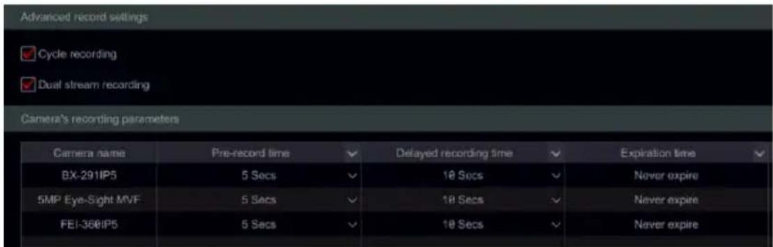
text_image
Advanced record settings ✓ Cycle recording ✓ Dual stream recording Camera's recording parameters Camera name Pre-record time ✓ Delayed recording time ✓ Expiration time ✓ BX-291IP5 5 Secs ✓ 10 Secs ✓ Never expire 5MP Eye-Sight MVF 5 Secs ✓ 10 Secs ✓ Never expire FEI-360IP5 5 Secs ✓ 10 Secs ✓ Never expireCycle recording: The recording will work in FIFO method – First in first out – meaning that the oldest recording will be overwritten by new recording once the HDD is full.
Dual Stream Recording: Enable/Disable the sub-stream recording of the device.
Important note: Disabling sub-stream recording will increase the duration of main stream recording but will dramatically reduce system performance and disable many features that rely on the sub-stream recording in order to work.
Pre-alarm Record Time: set the record time duration before the alarm event started.
Post-alarm Record Time: set the record time duration after the alarm event ended.
Expiration Time: set the expiration time for recorded video. Recordings will not be kept longer than the specified duration even if the HDD is not full.
7.2 Encode Parameters Setting
Click Start→Settings→Record→Encode Parameters to access the interface shown below. Set the video encode, resolution, FPS, bitrate type, bitrate and audio of main stream for each of the cameras.
Important: this interface offers both “Event Recording Stream” and “Normal Recording Stream” configurations. Make sure to configure both. You can set the record stream for each
camera set all cameras together by clicking on ▼. Click “Apply” to save the settings.

text_image
Normal recording stream Camera name Stream type Encode Resolution FPS Bitrate Type Quality Bitrate Bitrate Limit Recommende Camera1 Main stream H.264 1920x1080 25 VBR Higher 5120Kbps 4268-7146Kbps Camera2 Main stream H.264 704x480 7 VBR Higher 768Kbps 266-444KbpsClick Start→Settings→Record→Stream Settings to go to “Sub-stream” interface. Set the sub-stream video encode type, resolution, FPS, Bitrate type and bitrate for each camera or for all cameras together by clicking on ▼. Click “Apply” to save the settings.
| Camera name | Stream type | Encode | Resolution | FPS | Bitrate Type | Quality | Bitrate | Bitrate Limit Recommer |
| Camera1 | Sub-stream | H.264 | 1920x1080 | 25 | VBR | Higher | 1024Kbps | 1024~7146Kbp |
| Camera2 | Sub-stream | H.264 | 704x480 | 7 | VBR | Higher | 768Kbps | 266~444Kbps |
7.3 Schedule Setting
7.3.1 Add Schedule
Click Start→Settings→Record→Recording Schedule→Edit Schedules (Available only in manual recording mode). The pre-set schedules are “24 x 7” (All week), “24 x 5” (Weekdays - Monday to Friday) and “24 x 2” (Weekends – Saturday & Sunday). “24 x 7” schedule cannot be deleted or modified while “24 x 5” and “24 x 2” can be edited or deleted. Click the schedule name to display the detailed schedule information on the left side of the interface. The lines on the left stand for the seven days of the week. Each line stands for the daily 24 hours. Red marks the active selection and grey marks inactive selection.
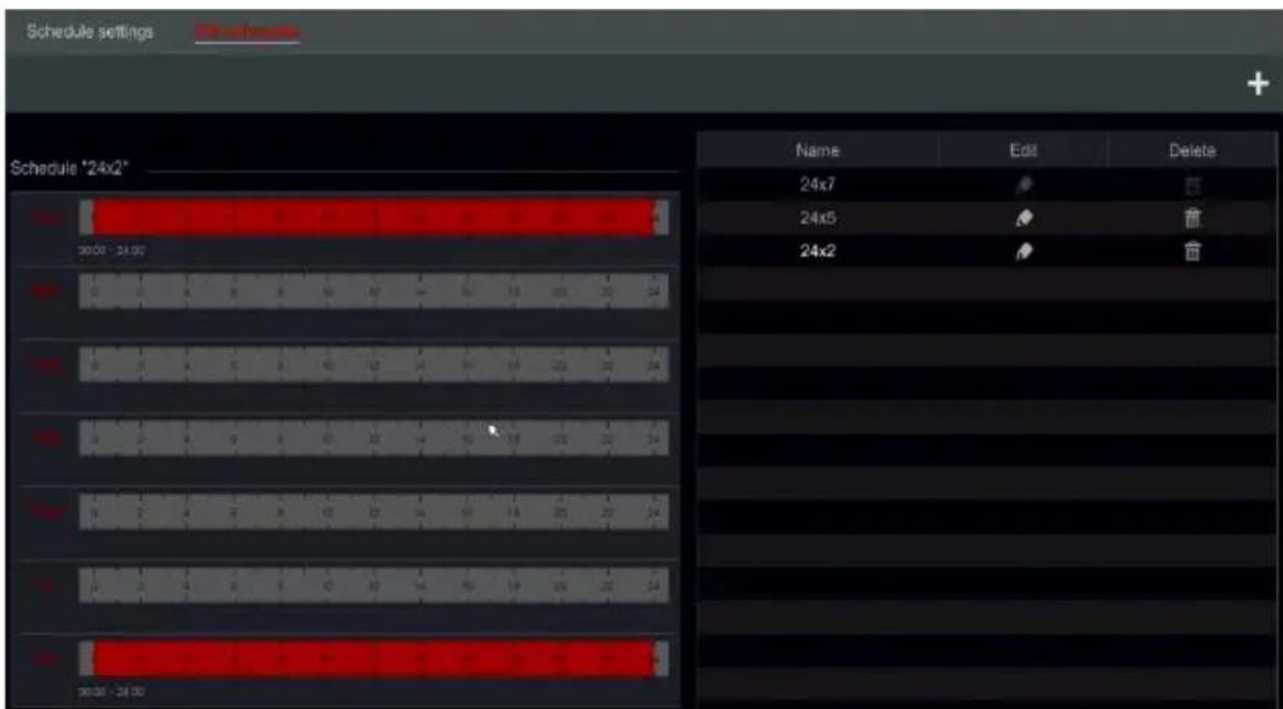
text_image
Schedule settings Schedule '24x2' Name Edit Delete 24x7 24x5 盲 24x2 盲 00:00 - 24:00 1 2 3 4 5 6 7 8 9 10 11 12 13 14 15 16 17 18 19 20 21 22 23 24 0 1 2 3 4 5 6 7 8 9 10 11 12 13 14 15 16 17 18 19 20 21 22 23 24 00:00 - 24:00Click to add a new schedule or to edit an existing one. Refer to the picture below.
Input the schedule name, set the schedule times and click "Add" to save the schedule. You can set day schedule or week schedule. live duration button active duration button.
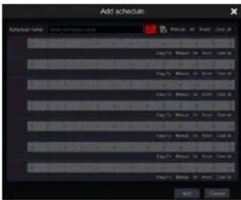
text_image
Add schedule Schedule name: Edit schedule name: Copy To: Manual # Insert Close at Copy To: Manual # Insert Close at Copy To: Manual # Insert Close at Copy To: Manual # Insert Close at Copy To: Manual # Insert Close at Copy To: Manual # Insert Close at Copy To: Manual # Insert Close at Copy To: Manual # Insert Close at Copy To: Manual # Insert Close at Copy To: Manual # Insert Close at Add Cancel➢ Set Single Day Schedule
Click drag the mouse cursor on the time scale of a specific day to mark the active duration. Click drag the cursor on the time scale of a specific day to make a selected area inactive.
You can manually set the record start time and end time: select “Manual” from beneath the day bar and set the desired time. Click “Ok” to confirm.
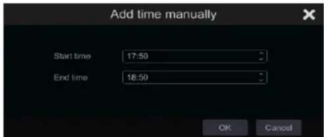
text_image
Add time manually Start time 17:50 End time 18:50 OK CancelClick “All” to set all day recording; click “Reverse” to swap the marked and unmarked areas; Click “Clear All” to clear all the selected area in a day.
After completing a setting for any day you can click “Copy To” from beneath the day bar to copy the selected schedule to other days. Refer to the picture below. After clicking on “Copy To” from the source day, check the destination days in the window and click “OK” to save.
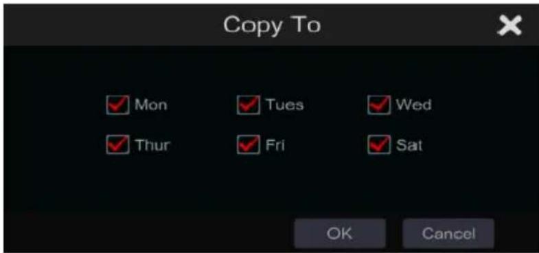
text_image
Copy To ✓ Mon ✓ Tues ✓ Wed ✓ Thur ✓ Fri ✓ Sat OK Cancel➢ Set Multi-Day Schedule
Use “Manual” beside 📋 to set the weekly schedule. Refer to the picture below. Set the start and end time, check the days in the window and click “OK” to save the settings.
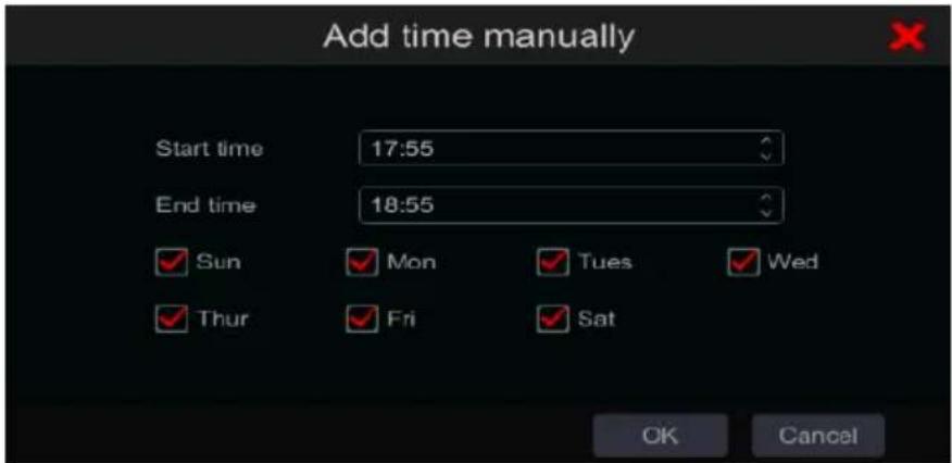
text_image
Add time manually Start time 17:55 End time 18:55 Sun Mon Tues Wed Thur Fri Sat OK CancelClick “All” to set all week recording; click “Reverse” to swap the selected and unselected time in a week; click “Clear All” to clear all the selected area in a week.
7.3.2 Record Schedule Configuration
Click Start→Settings→Record→Recording Schedule→Schedule Configuration to go to the interface shown below. Define the schedule for sensor, motion, analytics, POS and normal recording. Click “None” in the drop-down menu to clear the selected schedule.
Click "Apply" to save the settings.
| Camera name | Sensor recording schedule | ✓ | Motion recording schedule | ✓ | Analytics Record Schedule | ✓ | POS Record |
| BX-291IP5 | <None> | ✓ | <None> | ✓ | <None> | ✓ | <Non |
| 5MP Eye-Sight MVF | <None> | ✓ | <None> | ✓ | <None> | ✓ | <Non |
| FEI-368IP5 | <None> | ✓ | <None> | ✓ | <None> | <Non |
If any changes need to be made, go to the “Edit Schedules” interface and click 📋 to edit the schedule. The settings of “Edit Schedule” are similar to that of the “Add Schedule”.
7.4 Record Mode
7.4.1 Manual Recording
Method One – Manual record for all channels: Click 📄 on the tool bar at the bottom of the live-view interface to enable manual recording for all cameras.
Method Two – Manual record for single channel: In the live-view interface – either right click on the desired camera and choose “Manual Record On” or left click on the desired camera window and click 📄 on the channel tool bar.
Note: Click Start→Settings→Record→Mode Settings and set the manual record duration in the referred menu. Click "Apply" to save the settings. Default settings is "Manual"
7.4.2 Scheduled Recording:
Scheduled Recording: the system will record automatically according to the schedule weather there is an additional alarm or not.
Set the record schedule of each camera - See 7.3 Schedule Setting for details.
7.4.3 Motion Based Recording:
The system will start recording based on motion alarms. You can use the default settings or create customized setting for each camera as follows:
① Set the motion alarm schedule for each camera. See 7.3 Schedule Setting for details.
② Enable the motion and set the motion area of each camera. See 9.2.1 Motion Configuration for details.
The camera will start motion based recording as soon as the above settings are applied.
7.4.4 Sensor Based Recording:
The system will start recording based on sensor alarms. Configure the recording parameters as follows:
① Set the sensor alarm schedule for each camera/alarm input. See 7.3 Schedule Setting for details.
② Set the NO/NC type of the sensor, enable the sensor alarm and check and configure the "Record". See 9.1 Sensor Alarm for details.
7.4.5 Analytics Based Recording:
The system will start recording based on analytics alarms. Configure the recording parameters as follows:
① Set the analytics alarm schedule for each camera. See 7.3 Schedule Setting for details.
② Set each one of the available analytics alarms and check and configure the “Record”. See 9.1 Sensor Alarm for details.
7.5 Disk Management:
Click Start→Settings→Disk→Disk Management. On this interface you can view the device's disk numbers, status and recording dates stored on each drive. Click "Format" button to format the desired HDD or click on to format all drives together.
| Disk Mode | ||||||||
| Disk | Capacity[GB] | Free Space[GB] | Disk serial No. | Disk model | Status | Type | Record Period | Operation |
| Disk1 | 931 | 928 | 26MREB1NS | TOSHIBA DT01ACA100 | ✓ Disk no... | Ordinary PI... | Format | |
| Disk2 | 931 | 928 | 28MRRKVNS | TOSHIBA DT01ACA100 | ✓ Disk no... | Ordinary PI... | Format | |
| Disk3 | 931 | 928 | 26MRRJZNS | TOSHIBA DT01ACA100 | ✓ Disk no... | Ordinary PI... | Format | |
| Disk4 | 931 | 928 | 26MRRLINS | TOSHIBA DT01ACA100 | ✓ Disk no... | Ordinary PI... | Format | |
Note: 1. New HDD/s should be formatted before it can be used by the system.
- If the HDD has been used in another device of the same model, please import the configuration file of the old device to the new device or format the HDD; if the models of the two devices are different, please format the HDD.
7.5.1 Storage Mode Configuration
Click Start→Settings→Disk→Storage Mode.
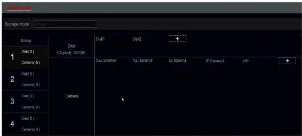
text_image
Storage mode Group Disk (Capacity: 800GB) Disk1 Disk2 + 1 Disk(2) Camera(5) Camera DAI-380IPVF DAI-390IPVF IS-390IP04 IP Camera1 z30 + 2 Disk(0) Camera(0) 3 Disk(0) Camera(0) 4 Disk(0) Camera(0)There are four available disk groups. By using disk group, you can allocate a specific camera to a specific disk (the recorded data from the grouped cameras will be stored in the disks allocated for that group).
Newly added disks and cameras will be joined into group one as default. The disks and cameras in the different groups can be deleted except of group one (select a disk group and click on the top right corner of the added disk or camera to delete it from the group). The deleted disks and cameras will be moved into group one automatically.
Each group can receive disks and cameras from other groups. Each disk/camera can be allocated to one group only.
Edit Disk/Camera Groups:
Select a disk group and click in the disk or camera row to pop up a window. Check the disks or cameras in the window and click "Add".
Important: Changing group allocation for a disk/camera will result in losing data of the changed disk/camera.
7.5.2 Disk Mode (Models supporting RAID only):
Disk mode allows you to enable RAID (If supported by the device). Once the RAID is enabled, the device will reboot and new options will be available.
7.5.3 Physical Disk (Models supporting RAID only):
This menu is available only if RAID is enabled. Here you will see all the disks and their current status. Before you can start recording, you will need to assign the disks to RAID groups or assign it as “Hot Spare”.
| Disk management | Name/Os | Array | Disk Mode | ||||
| T | Disk | Capacity[GB] | Array | Type | Status | Disk model | Hot Spare |
| 1 | 931 | tal | Array disk | Normal | DT81ACA199 | ||
| 2 | 931 | tal | Array disk | Normal | DT81ACA199 | ||
| 3 | 931 | tal1 | Array disk | Normal | DT81ACA199 | ||
| 4 | 931 | tal1 | Array disk | Normal | DT81ACA199 | ||
Creating an array:
In order to assign disks, click on "Create Array". The following window will appear.
Set a name to the new array and choose the array type. The available options are RAID0, RAID1, RAID5, RAID6, RAID10. (For more information
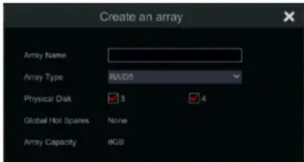
text_image
Create an array Array Name Array Type RAID5 Physical Disk 3 4 Global Hot Spares None Array Capacity 8GBabout RAID types, please refer to appendix 2 at the end of the manual).
Choose the disks that you want the array to include (Note that different RAID types require different number of disks.
Click "Add" to finalize the process.
Notes:
1) All the data stored on the HDD will be deleted.
2) Up to 2 RAIDs can be configured.
Setting a "Hot Spare"
In terms of RAID, “Hot Spare” is a backup disk that is ready for use in case that an active array disk has failed. In such case, the hot spare will replace the failed array disk automatically and rebuilt its data (a process that takes time). The “Hot spare” of the system is global meaning that it will be used for all RAIDs configured on the system.
In order to assign a disk to perform as “Hot Spare”, click on the 🔊 icon next to it and confirm the process. Repeat the process to change it back to normal state.
7.5.4 Array (Models supporting RAID only):
This menu is available only if RAID is enabled. Here you will see all the created RAID groups and their current status (Name, Capacity, Assigned Disks, Hot Spares, Status). Also, you will be able to delete the arrays and rebuilt it if required.
| Disk management | Physical Disk | Disk Mode | |||||||
| No. | Name | Capacity[GB] | Physical Disk | Hot Spare po... | Status | Type | Rebuild | Delete | Task |
| 1 | tal | 931 | 1 2 | 3 | Normal | RAID1 | |||
➢ Rebuilding an array:
In case one of the disks of the array failed – the array state will change to “downgraded” and the rebuild button will become active as follows.

text_image
Status Type Rebuild Normal RAID1 → Status Type Rebuild Downgrade RAID1Once the faulty disk was replaced with a new one, click on the “rebuild” to restore the array state to normal.
▶ Deleting an array:
If you wish to delete an array, click on the button and confirm the process.
7.5.5 View Disk and S.M.A.R.T. Information:
Click Start→Settings→Disk→View Disk Information; click “S.M.A.R.T. Information” to view the working status of the HDD. Refer to the picture below.
8 Search, Playback & Backup
8.1 Instant Playback
Click 📄 the channel tool bar at the bottom of the live-view camera window to play back the record (click 🔗 on the general tool bar at the bottom of the live-view interface to set the default playback time). Drag the playback progress bar to change the playback time. You can also click the right-click menu “Instant Playback” in the camera window and set the instant playback time to play back the record.
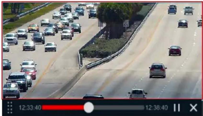
natural_image
Highway traffic scene with multiple cars and a tree-lined road, captured in video player interface (no readable text or symbols)8.2 Playback Interface Introduction
Click the general tool bar at the bottom of the live-view interface or click Start→Playback. (Click on the general tool bar at the bottom of the live-view interface to set the default playback time).
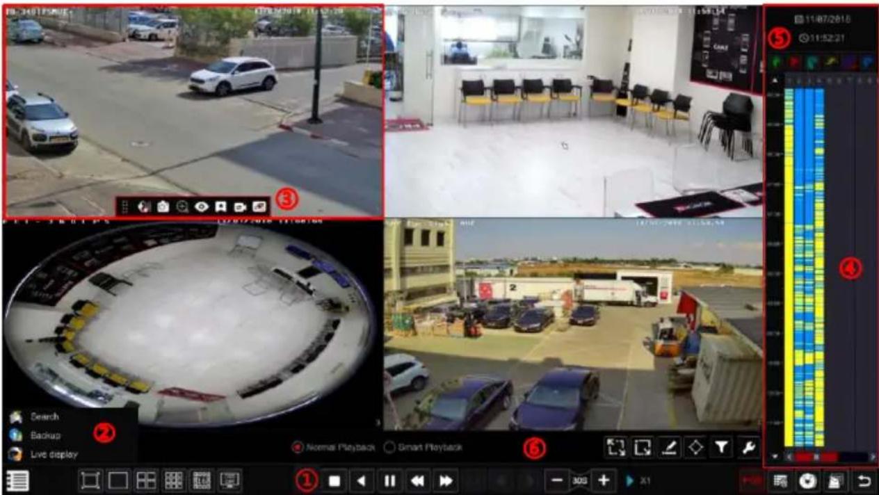
text_image
Screenshot of a car security camera interface with multiple surveillance feeds and a color-coded playback panel on the right.The interface will switch from live-view to playback and the cameras from the live-view will be played back automatically. You can add the playback cameras manually by clicking on in the playback window to open the “Add Camera” window. Mark the cameras you wish to add and click “Add”. The system supports a maximum of 16 synchronous playback cameras.
The buttons of the general tool bar (area ①) are introduced in the table below:
| Button | Meaning | |
 | Start button. Click it to pop up area 2. | |
 | Full screen button. Click it to show full screen; click it again to exit the full screen. | |
 | Screen split modes. | |
 | “OSD ON/OFF” button. Click it to enable/disable the OSD | |
 | Stop button. | |
 | Rewind button. Click it to play video backward. | |
 | Play button. Click it to play video forward. | |
 | Pause button. | |
 | Decelerate button. Click it to decrease the playing speed. | |
| [22XW] | Acceleration button. Click it to increase the playing speed. | |
 | Return to normal playback speed (x1) | |
 | Previous frame button. It works only when the forward playing is paused in single screen mode. | |
 | Next frame button. It works only when the forward playing is paused in single screen mode. | |
 | Click to step backward 30s and click to step forward 30s. | |
 | Enable/Disable Watermark appearance (Applicable for DVRs only) | |
 | Enable/Disable POS data appearance | |
 | Event list/tag button. Click it to view the event records of manual / schedule / sensor / motion and the tag information. | |
 | Backup button. Drag the mouse on the time scale to select the time periods and cameras and click the backup button to back up the record. (After marking the area for backup you can also click on the right mouse button) | |
| [A4WS] | View the backup status. | |
 | Back button. Click it to return. | |
Introduction of area ②:
| Button | Meaning |
 | Go to record search & backup interface; see 8.3 Record Search, Playback & Backup for details. |
 | Click it to go to live-view interface; see Chapter 5 Live Preview Introduction for details. |
Click on the playback window to show the tool bar as shown in area ③; right click on the window to show the menu list. The tool bar and menu list are introduced in the table below.
| Button | Menu List | Meaning |
 | -- | Move tool. Click it to move the tool bar. |
 | Enable Audio | Click it to enable audio and listen to the camera's audio channel. |
 | Snap | Click it to take a snapshot. Not supported by “X” models when playback is paused. |
 | Zoom In | Click it to go to the digital zoom. The playback digital zoom interface is similar to live-view digital zoom interface. Click to pause the playback. When the record is paused while in forward playing mode, you can click to view the previous frame and click to view the next frame. |
 | Fish Eye | Click it to open controls for Fish-Eye cameras as described in the “Live-View” Chapter. |
 | Add Tag | Save a tag of the exact date and time you wish to save. You can use the tag later to go back quickly to the tagged point. When adding a new tag the system will name it with the saved time automatically. You can change the name or edit it later. |
 | Switch Camera | Click it to switch the playback camera to a different camera that will playback the exact date and time. Click it and choose the new camera in the window. Click “OK” to change the camera. |
 | Close Camera | Click it to close the playback camera. |
Introduction of area ④:
| Button | Meaning |
 | Set/Change the playback date |
 | Set/Change the playback time |
* | Manual Record markings. Uncheck it to remove manual record display |
* | Sensor Alarm Record markings. Uncheck it to remove manual record display |
* | Analytics Alarm Record markings. Uncheck it to remove manual record display |
* | Motion Alarm Record markings. Uncheck it to remove manual record display |
* | Schedule Record markings. Uncheck it to remove manual record display |
* | POS Record markings. Uncheck it to remove manual record display |
** Playback must be stopped completely before these icons can be used. After stopping the playback use +on to add the desired cameras for search/playback.
Introduction of the record time scale (area ⑤):
| Button | Meaning |
| [WWCB] | The time-scale default view is 24 hours. Click on this icon to return to 24 hours view |
 | Zoom in/out within the playback time scale |
 | Move up the time scale (The mouse wheel can also be used) |
 | Move down the time scale (The mouse wheel can also be used) |
The record time scale shows different record types with different colors. The green color stands for manual record, red color stands for sensor alarm record, yellow color stands for motion alarm record and blue color stands for schedule record. Click the time scale to set the playback exact location.
Drag the mouse cursor on the time scale to select the backup area and right click on the marked area or click 🔒 to pop up a backup information window. Select the destination device, backup path and backup format and click “Backup” to start the backup process.
Introduction of “Smart Playback” (Area ⑥):
Smart Playback allows you to perform simple analyzing of recorded video while playing it back, saving a lot of time and efforts.
Note: Smart Playback is available for recording devices running Ossia v1.3.x. All analog cameras are supported together with IPC running v4.2.1 or higher.
| Button | Meaning |
| Standard playback controls | |
| Smart playback controls | |
| Full screen motion search | |
| Square selection motion search | |
| Line Crossing (Bi-Directional) | |
| Polygon selection (up to 4 Corners) | |
| Apply a face recognition filter (If applicable) | |
| Smart Search configuration. |
If you wish to apply an additional face recognition filter to the smart search, click on the icon to open the filter interface.

In the following interface tick “Enable face playback” in order to activate the face filter and set the similarity value.
You can choose face/faces from the following options:
1) Face database - Search from faces already in the database.
A) Here you can choose from the thumbnails or search by name. Click on "More" to narrow down groups or tick "All" to search/display within all groups.
B) Tick the face/faces you wish to search for and click on Search by face/group as needed.
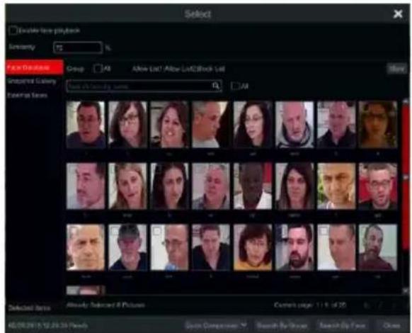
text_image
Double Face Playback Sensitivity: 75 % Face Options: Group: 40 Alive List! Alive List2Block List Inspired Gallery Faceplay Series Selected Items: Already Selected @ Pictures Camera's page 11.8 of 30 65/09/2018/12/29/2018 Preview Search Comparison: % Search By Group Search By Focus Close2) Snapshot Gallery – Search within snapshots taken by the system
A. Set the time range for the face snapshot search. (Day to choose a day, Week to choose a week, Month to choose a month, customization to set a unique time range and Today to choose the date of today starting at midnight).
B. Choose the camera/cameras that took the face snapshot. Click on "More" to choose specific cameras or tick "All" to choose all cameras.
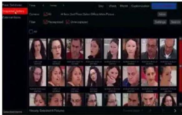
text_image
Face Swifter Form C Sigma S Day Sheet Month Customizations Visual Connections Commerce All 4 face Swifter Sales Office More Pictures Name Image Unrealized Settings Search Selected News Already Selected in Pictures Current format: 1.00C. Choose weather you like to see recognized and unrecognized faces in the search.
D. Tick the face/faces you wish to search for and click on Search by face/group as needed.
3) External Faces – Choose a picture file that contain a single face from a USB storage.
A. Select the USB storage under the "Device Name"
B. Select the relevant file (Must contain a single clear face).
C. Click on Search face.
text_image
File Edit Options Named Image Edit Name Origin Focus Import History Description Substituted Image Advanced Selected ImageSmart Search Settings: Click on the icon to open the settings menu: Here you can set if to skip unrequired video or play it.
You can set the playback speed for required video and unrequired video (if requested), and set the intrusion percentage into the marked area in order to improve detection rate.
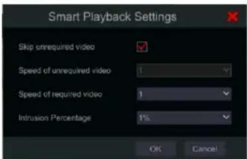
text_image
Smart Playback Settings Skip unrequired video Speed of unrequired video 1 Speed of required video 1 Intrusion Percentage 1% OK CancelAfter applying smart playback filter you will see that the time bar will display the original time bar next to the filtered time bar as follows:

text_image
Record Search, Playback & Backup Full details Filtered details8.3 Record Search, Playback & Backup
8.3.1 Search & Playback by Time-sliced Image
① Click Start→Search & Backup→By Time-sliced Image.
The “Time-Sliced Image” search is designed to quickly find a small change in the scene that might have happened in a split of a second.
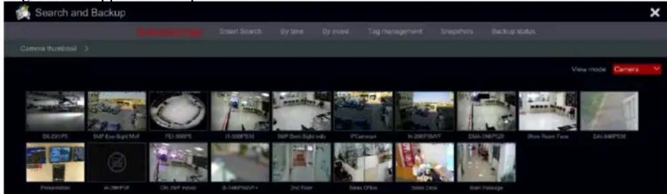
text_image
Search and Backup Camera thumbnail > View mode Camera OK-231/PS SMP Eye-Sight MVF FEI-300/PS II-300/PS34 SMP Dark-Sight India iPCammal M-288/PS34V DAA-288/PS28 Shoe Room Face DAI-348/PS38 Preservation IA-398/PSF CRI SNAP Inveror B-348/PS34V 2nd Floor Sawn Office Sawn Deck Room PackageThere are two view modes: by time and by camera. In the time view mode, a maximum of 64 camera thumbnails can be showed. If the camera thumbnail number is greater than 64, the cameras will be listed by their camera name, and not as a thumbnail. A maximum of 196 camera names can be listed. If the camera name number is more than 196, the time view mode will be disabled and only the camera view mode will be available.
② Double click on the selected camera or select one camera and click the “Open” button. The camera will refine from “Day” view to “Hour” view. Repeat this stage to refine from “Hour” view to “Minute” View.
③ You can also click once on the thumbnail to commence playback on the left window. This will help you to confirm if you are in the right camera/time.
④ Once in “Minute” view, double clicking on any image thumbnail will open the full playback interface and commence playback for the selected camera at the specific time and date.
⑤ You can click once on the image box to play the record in the small playback box on the left side of the interface (If the thumbnail is blackened out – it means there is no record data available)
⑥ You can perform backup directly from this interface in two methods:
A. Left click and drag the mouse on the time scale to select the segment for playback and click "Backup" button to continue; select the device, backup path and backup format in the opened window and click "Backup" button to start the backup.
B. After choosing the channel, click on “Set Backup Time” and input the start and end times. Confirm by clicking on “OK” and start the backup process using the “Backup” button.
⑦ Click “Playback” button (Or double click on the thumbnail) to commence playback in the playback interface (refer to 8.2 Playback Interface Introduction for details). Click “Close” to close the interface.
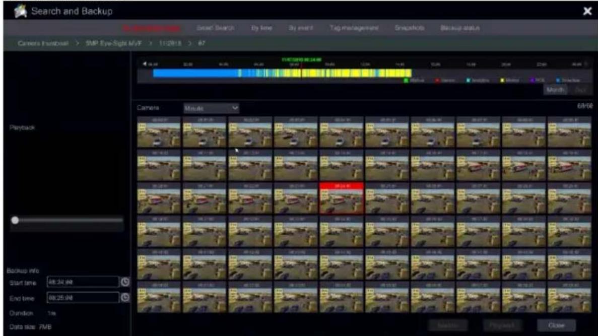
text_image
Search and Backup In-entrations Search Search By time By insert Tag management Snapshots Backup status Camers In-Backball > 5MP Eye-Sight MVF > 11:28:18 > 67 11:43:00:00:24:00 Playback 68/66 Backup info Start time: 08:24:00 End time: 08:25:00 Duration: 1ms Data size: 7MBTime Slice Mode Working method:
Method One: Click “Year”, “Month” or “Day” button under the record time scale to select the time slice mode. In “Day” mode, click / ▶ on the left/right side of the time scale to jump to the next/previous day; click “Minute” in the “Picture” option under the time scale to select “Minute” mode (in “Minute” mode, click the time scale to change the time of the 60 display windows) and click “Hour” to select “Hour” mode.
Method Two: Click > beside “Camera Thumbnail” on the left top corner of the interface to select the time slice mode.
Method Three: Right-click the mouse on any area of the time-sliced interface to go back to the upper interface.
8.3.2 Search, Playback & Backup by Smart Search:
① Click Start→Search & Backup→Smart Search.
② Choose on the left pane the camera you wish to playback (Only one camera can be selected)
③ Smart Playback allows you to perform simple analyzing of recorded video while playing it back, saving a lot of time and efforts.
Note: Smart search is available for recording devices running Ossia v1.3.x. All analog cameras are supported together with IPC running v4.2.1 or higher.
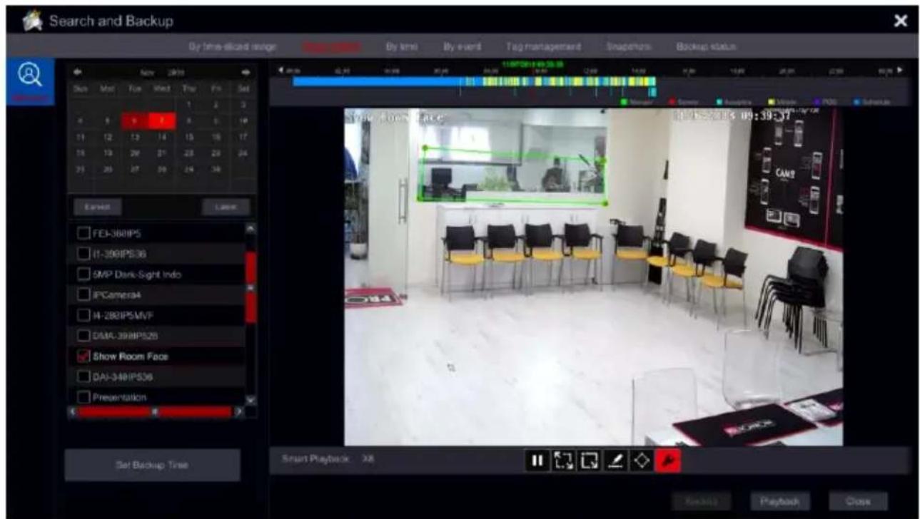
text_image
Search and Backup By time-diluted remote Time By time By event Tag management Snapshots Backup status Skin Myc Face Wind Taur Fts Set 4 5 6 7 8 9 10 11 12 13 14 15 16 17 18 19 20 21 22 23 24 25 26 27 28 29 30 31 32 33 34 Easterat Locks FEI-360IPS IT-398IPS36 SMP Dark-Sight Indo IPCamera94 IT-298IPSMVF DMA-398IPS28 Show Room Face DAI-348IPS36 Presentation Set Backup Time Smart Playback 30x Start Playback 30x Playback 30x Close| Button | Meaning | |
 | Full screen motion search | |
 | Square selection motion search | |
 | Line Crossing (Bi-Directional) | |
 | Polygon selection (4 Corners) | |
 | Smart Search configuration. | |
④ Face Recognition Filter (For applicable devices only)
⑤ Smart Search Settings: Click on the 📁 icon to open the settings menu: Here you can set the intrusion percentage into the marked area in order to improve detection rate.
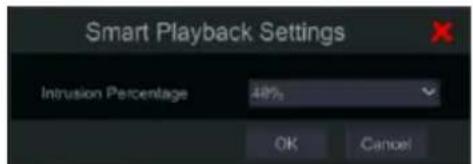
text_image
Smart Playback Settings Intrusion Percentage 48% OK Cancel8.3.3 Search, Playback & Backup by Time:
① Click Start→Search & Backup→By Time.
② Click 📋 on the bottom of the interface to choose the cameras (A maximum of 16 cameras can be added). Click “Modify” on the top right corner of the camera window to change the camera or click “Clear” to remove the camera.
③ Single click on the camera window to play the record in the small playback box on the left side of the interface. You can set the date on the top left of the interface, check the event type as required and click the time scale or click under the time scale to set the time. The camera window will play the record according to the time and event type you set.
④ Single click on the time bar to set the time for playback. The camera thumbnails will be
updated automatically and show a snapshot from the chosen time.
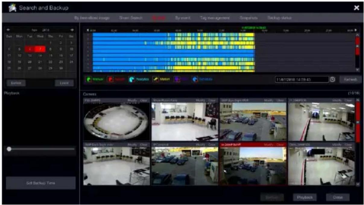
text_image
Search and Backup By International Image Smart Search By event Tag management Snapshots Backup status 11/07/2018 14:56:43 11/07/2018 (14:59:43) Refresh Playback Set Backup Time Camera (16/16) Main Tue Wed Thu Fri Sat 0 5 0 0 0 0 17 12 13 14 15 16 17 18 19 20 21 22 23 24 25 26 27 28 29 30 Manual Analytics Motion Connectivity Map Data Tools Add Modify Clear Map Data Tools Add Modify Clear Map Data Tools Add Modify Clear Map Data Tools Add Modify Clear Map Data Tools Add Modify Clear Map Data Tools Add Modify Clear Map Data Tools Add Modify Clear Map Data Tools Add Modify Clear Map Data Tools Add Modify Clear Map Data Tools Add Modify Clear Map Data Tools Add Modify Clear Map Data Tools Add Modify Clear Map Data Tools Add Modify Clear Map Data Tools Add Modify Clear Map Data Tools Add Modify Clear Path Back Close Playback Close⑤ You can perform backup directly from this interface. Left click and drag the mouse on the time scale to select the segment for playback and click “Backup” button to continue; select the device, backup path and backup format in the opened window and click “Backup” button to start the backup.
⑥ You can perform backup directly from this interface in two methods:
a) Left click and drag the mouse on the time scale to select the segment for playback and click "Backup" button to continue; select the device, backup path and backup format in the opened window and click "Backup" button to start the backup.
b) After choosing the channel, click on "Set Backup Time" and input the start and end times. Confirm by clicking on "OK" and start the backup process using the "Backup" button.
⑦ Click “Playback” button (Or double click on the thumbnail) to commence playback in the playback interface (refer to 8.2 Playback Interface Introduction for details). Click “Close” to close the interface.
8.3.4 Face Database Management
① Click Start→Search & Backup→Face Database.
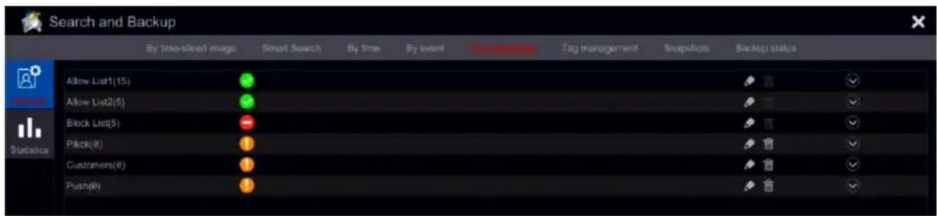
text_image
Search and Backup By time-speed image Smart Search By time By event Post-Source Tag management Snapshots Backup status Allow List1(15) Allow List2(5) Block List(5) Pick(0) Customers(0) Push(0)② In This section you will be able to create, edit and manage your face database.
③ By default, the database contains 3 groups:
a) Allow List1, Allow List2: Members of these groups are permitted 24/7
b) Block List: Members of this group are not permitted 24/7
④ You can create new groups by clicking on “Add Group”. You can configure “Permitted” time for members of customized groups.
⑤ Click on 📋 to edit a group name and on cannot be deleted).

to delete a group (The default groups
⑥ Click on to open a group.
Adding a new person to the database:
① Click on “Add” to add a new person. The following interface will open.
② Choose the source of the face snapshot. Snapshot Gallery – Search within snapshots taken by the system or External Faces – Choose a picture file that contain a single face from a USB storage.
③ Click on the “+”
④ If you chose “Snapshot Gallery” the following interface will open:
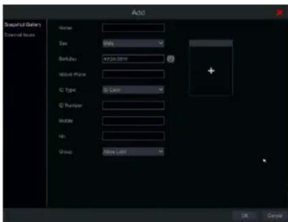
text_image
Add Drawout Gallery External Room Name: Code: Mily Radius: 47.26 mm Absolute Place: ID Type: B Case ID Number: Multiple: Size: Group: Above Left1 OK CancelA. Set the time range for the face snapshot search. (Day to choose a day, Week to choose a week, Month to choose a month,
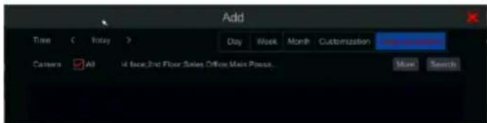
text_image
Add Time Event Day Week Month Customization Camera All 4 base 2nd Floor Sales Office Main Process.... Muse Searchcustomization to set a unique time range and Today to choose the date of today starting at midnight).
B. Choose the camera/cameras that took the face snapshot. Click on "More" to choose specific cameras or tick "All" to choose all cameras.
C. Click on "Search"
D. Choose the face you wish to input to the database. Click on "OK"
E. Fill the rest of the details in the form. (Only the name is mandatory. All the other fields are optional)
⑤ External Faces – Choose a picture file that contain a single face from a USB storage.
A. Select the USB storage under the "Device Name"
B. Select the relevant file (Must contain a single clear face).
C. Click on Select face.
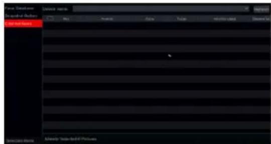
text_image
Auto & Books Auto and Books Auto and Books Automotive: Auto and BooksNote: that for good recognition results, the face must be well lit, looking straight to the camera with as many visible face features as possible (Eyes, pupils, ears, nose, mouth etc.)
If you input a new person to a customized group, you will also have a validation period option
meaning that the person will be recognized as permitted only within the specified time range.
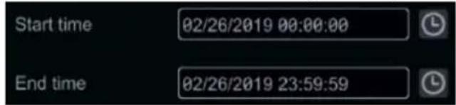
text_image
Start time 02/26/2019 00:00:00 End time 02/26/2019 23:59:59Modifying a person in the database:

① Click on 📋 to open a group.
② Select a person and click on “Modify”
③ The person's card will open. You will be able to edit any of the details and change the assigned group of the person.
Deleting a person from the database:

① Click on 🤕 to open a group.
② Select a person and click on “Delete”
③ The system will prompt for deletion.
Clicking on "Clear All" will delete all the people in the specified group.
Exporting the database:
① Click on Export and Import to open the following interface.
② Click on “Export” to export the database. Set the database name and target location.
③ Set a password
④ The database will be encrypted and exported to the target location.
Exporting the database:
① Click on Export and Import to open the following interface.
② Choose the database file and click on “Import”
③ Inpit the database password to initialize the import procedure
④ The database will be created on the device. The device will reboot automatically at the end of this procedure.
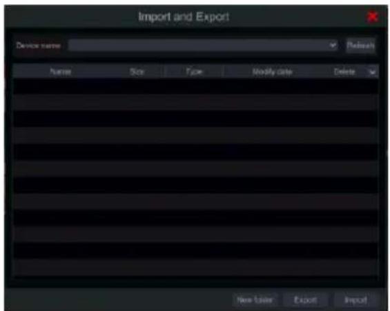
text_image
Import and Export Device name Refresh Human Size Type Modify Date Delete New Order Export ImportNote: the database is stored on the HDD. Formatting the HDD will delete the database as well. Importing a database will automatically overwrite the existing database.
8.3.5 Face Recognition Statistics
① Click Start→Search & Backup→Face Database.
② On the left pane, click on Statistics. The interface below will open.
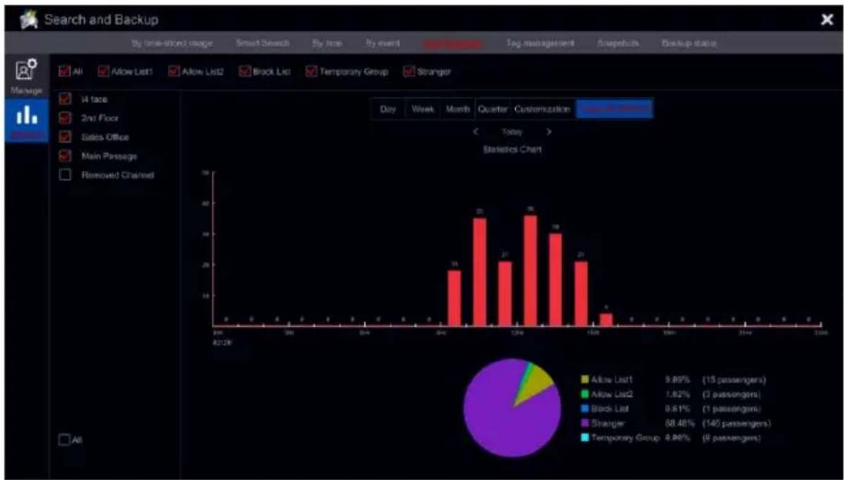
bar
| Category | Count | | :--- | :--- | | All | 9.89% (15 passengers) | | Allow List1 | 1.62% (3 passengers) | | Allow List2 | 0.61% (1 passengers) | | Block List | 88.46% (140 passengers) | | Temporary Group | 4.86% (8 passengers) |③ Choose the required groups and cameras.
④ Set the time range for the statistics display. (Day to choose a day, Week to choose a week, Month to choose a month, Quarter to choose a quarter, customization to set a unique time range and Today to choose the date of today starting at midnight).
8.3.6 Search, Backup & Playback by Event
① Click Start→Search & Backup→By Event.
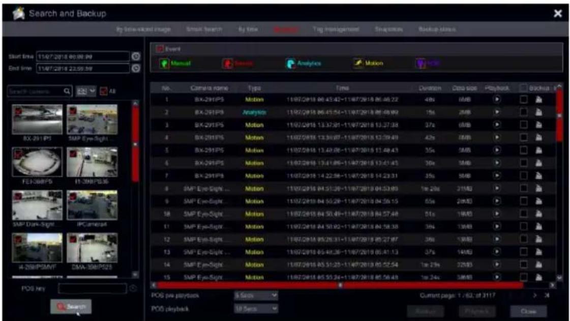
text_image
Search and Backup Up time-old image Smart search By time Mouse Tag in-transported Snapshots Backup status Event Manual Analysis Motion No. Camera name Type Time Duration Data size Playback Booklet 1 BX-291IP5 Motion 11/07/2018 00:43:42-11/07/2018 00:46:22 48x 1MB 2 BX-291IP5 Analysis 11/07/2018 06:45:54-11/07/2018 06:59:92 15x 2MB 3 BX-291IP5 Motion 11/07/2018 13:37:51-11/07/2018 13:37:38 37x 6MB 4 BX-291IP5 Motion 11/07/2018 13:39:87-11/07/2018 13:39:49 42x 1MB 5 BX-291IP5 Motion 11/07/2018 13:40:86-11/07/2018 13:40:43 35x 5MB 6 BX-291IP5 Motion 11/07/2018 13:41:89-11/07/2018 13:41:43 36x 5MB 7 BX-291IP5 Motion 11/07/2018 14:22:56-11/07/2018 14:23:31 35x 5MB 8 SMP Eye-Sight ... Motion 11/07/2018 04:51:39-11/07/2018 04:53:89 1m 2Mx 21MB 9 SMP Eye-Sight ... Motion 11/07/2018 04:55:28-11/07/2018 04:56:15 55x 2Mx3 10 SMP Eye-Sight ... Motion 11/07/2018 04:50:49-11/07/2018 04:57:48 51x 1MB 11 SMP Eye-Sight ... Motion 11/07/2018 04:53:52-11/07/2018 04:58:38 36x 1MB 12 SMP Eye-Sight ... Motion 11/07/2018 05:29:31-11/07/2018 05:27:87 36x 1MB 13 SMP Eye-Sight ... Motion 11/07/2018 05:49:36-11/07/2018 05:41:13 37x 1MB 14 SMP Eye-Sight ... Motion 11/07/2018 05:51:23-11/07/2018 05:52:54 1m 2Mx 32MB 15 SMP Eye-Sight ... Motion 11/07/2018 05:55:24-11/07/2018 05:56:49 1m 2Mx 3MB POS key POS pre-payback S Bars Current page 1 - 62; of 3I IY > X POS playback UP Seps Backs Players Close② Mark the required event type in the interface (Manual, Sensor, Motion or Analytics).
③ Click to set the start time and end time on the top left of the interface.
④ Mark the desired cameras on the left side of the interface and click Q Search to search the database. The searched records will be displayed in the list.
⑤ Click ▶ in the list to playback the record in a popup window. You can also select one record data from the list and click “Backup” button instant backup.
⑥ Select one record data from the list and click “Playback” button to play the record in the playback interface.
8.3.7 Search & Playback by Tag
You have to save tags prior to using this interface. While playing back click on one of the camera windows to open the camera menu bar and click on
Click Start→Search & Backup→Tag Management

text_image
Search and Backup By type-Blaced image Smart Search By time By email Snapshots Snapshots Backup status No. Name Camera name Time Playback Edit Delete ✓ 1 SMP Eye-Sight MVF_0P181187W45154 SMP Eye-Sight MVF 1197/2018 04:51:54 2 test SMP Eye-Sight MVF 1197/2018 04:52:12Click 📋 in the interface to play the record. Click 🔒 to edit the tag name. Click 🔒 to delete the tag.
8.3.8 Snapshots
Click Start→Search & Backup→Snapshots. The system will display all the snapped images.

text_image
Search and Backup By line-stated image Smart Search By true By event Tag management Backup status No Camera name Snapshot mode Snapshot time Creator Browse Export Deere 32 BMP Eye-Sight MVF Alarms 11/07/2018 15:05:27 BMP Eye-Sight MVF 33 2nd Floor Alarms 11/07/2018 15:05:28 2nd Floor 34 FBJ-36RIPS Alarms 11/07/2018 15:05:29 FBJ-36RIPS 35 Old 2MP Indoor Alarms 11/07/2018 15:04:58 Old 2MP IndoorClick to delete an image. Click to open the "Export" window. Select the device name and save path in the window and click "Save" button. Click to open a view window. Click to export the image. Click to view the previous image or click to view the next image. Click to delete the image; click to play all the images automatically one by one.
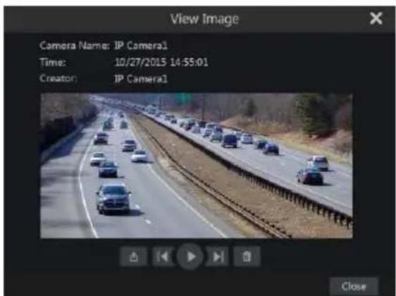
text_image
View Image Camera Name: IP Camera1 Time: 10/27/2015 14:55:01 Creator: IP Camera1 Close8.3.9 Backup Procedures
The recorded data and the snapped pictures can be backed up locally to USB (U-disk or external USB HDD) or by e-SATA (only available in selected models) it can also be backed up through network (only to AVI format). The file system of the backup devices must be FAT32 format or it will not be useable by the system.
① Refer to any of the Search & Backup methods and use the applicable backup methods.
② Once selecting the backup duration, click “Backup” button to open the “Record Backup” window as shown below. Select the device name, backup format and path and click “Backup” button to start the backup.
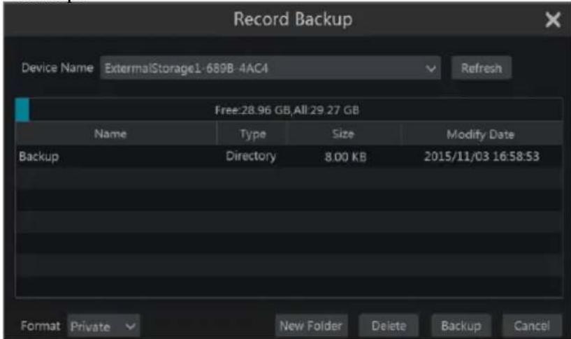
text_image
Record Backup Device Name ExternalStorage1-6898-4AC4 Refresh Free:28.96 GB,All:29.27 GB Name Type Size Modify Date Backup Directory 8.00 KB 2015/11/03 16:58:53 Format Private New Folder Delete Backup CancelNote: There are two backup formats available: AVI is a common video file that can be played by any video player. "Private" format can be played by "RPAS player" only. The RPAS player will be added to on the USB device automatically.
8.3.10 View Backup Status
Click Start→Search & Backup→Backup Status or click 📂 on the tool bar at the bottom of the playback interface to view the backup status.
This will show all the active backup procedures. From here you will be able to see the general progress of the backup tasks and pause or delete any of it.

text_image
Search and Backup By time-sliced image Smart Search By time By event Tag management Snapshots No. Time Duration Data size Path Creator Progress Details Operation Delete 1 11/11/2018 12:18:00-11/11/2018 12:52:00 42m 8s 2.65GB /mnt/u/ExternalStorage admin 3.20% Please Delete9 Alarm Management
9.1 Sensor Alarm
To fully configure the sensor alarm settings, you should enable the sensor alarm and set up the alarm handling for each camera/channel.
① Click Start→Settings→Alarm→Sensor Alarm to access the following interface.
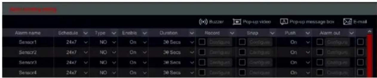
text_image
Buzzer Pop-up video Pop-up message box E-mail Alarm name Schedule Type Enable Duration Record Snap Push Alarm out Sensor1 24x7 NO On 30 Secs Configure Configure On Configure Sensor2 24x7 NO On 30 Secs Configure Configure On Configure Sensor3 24x7 NO On 30 Secs Configure Configure On Configure Sensor4 24x7 NO On 30 Secs Configure Configure On Configure② Select the alarm type (NO or NC) according to trigger type of the sensor.
③ Enable the sensor alarm for the desired cameras/channels.
④ Mark the and configure the desired response for sensor alarm out of “Record”, “Snap”, ,”Push Notification”, “Alarm-out” and “Preset”, and enable/disable “Buzzer”, “Pop-up Video”, “Pop-up Message Box” and “E-mail”.
⑤ Click “Apply” to save the settings.
The configuration steps for the alarm responses are as follows:
Record: once enabling “record” a “Trigger Record” window will pop up (you can also click “Configure” button to open the window manually). Select camera/s on the left side and click >> to set the camera as a triggered camera. Select a triggered camera from the right side and click << to remove the triggered camera. Click “OK” button to save the settings. The triggered camera/s will commence recording in case of a sensor alarm.
Snap: once enabling “Snap” a “Trigger Snapshot” window will pop up (you can also click “Configure” button to open the window manually). Select camera/s on the left side and click to set the camera as a triggered camera. Select a triggered camera from the right side and click to remove the triggered camera. Click “OK” button to save the settings. The triggered camera/s will take a snapshot in case of a sensor alarm.
Push: Tick if you wish to get push notifications for the selected input.
Alarm-out: once enabling “Alarm-Out” a “Trigger alarm-out” window will pop up (you can also click “Configure” button to open the window manually). Select alarm/s on the left side and click [icon] to set the alarm as a triggered alarm. Select a triggered alarm from the right side and click [icon] to remove the triggered alarm. Click “OK” button to save the settings. The triggered alarm will commence in case of a sensor alarm. You need to set the delay time and the schedule of the alarm outputs. See 9.4.1 Alarm-out for details.
Preset: once enabling “Preset” a “Trigger Preset” window will pop up. Configure the triggered preset of each PTZ camera. To add presets, please see 6.2 Preset Setting.
Buzzer: if enabled, the system will buzz using the internal buzzer when the sensor alarm is
triggered. To set the delay time of the buzzer, please see 9.4.4 Buzzer.
Pop-up Video: once enabling “Pop-up Video” a “Set Camera” window will pop up. Select a camera from the list as the triggered channel. Click “OK” button to save the settings. The triggered camera will open in a single channel live-view in case of sensor alarm. To set the duration time of the video pop up, please see 9.4.3 Display.
Pop-up Message Box: if enabled, the system will pop up the corresponding alarm message box automatically when a sensor alarm is triggered. To set the duration time of the message box, please see 9.4.3 Display.
E-mail: if enabled, the system will send an e-mail when a sensor alarm is triggered. Before you enable the email, please configure the e-mail addresses first (see 11.1.4 E-mail Configuration).
9.2 Motion Alarm
Motion Alarm: when motion appears in the specified area, it will trigger the motion alarm. Remember that the motion alarm is based on VMD which translates pixel color changes as motion, therefore might trigger false alarms.
You should enable and configure the motion detection for each of the cameras first and set the alarm handling to complete the motion alarm configuration.
9.2.1 Motion Configuration
① Click Start→Settings→Camera→Motion to access the following interface.
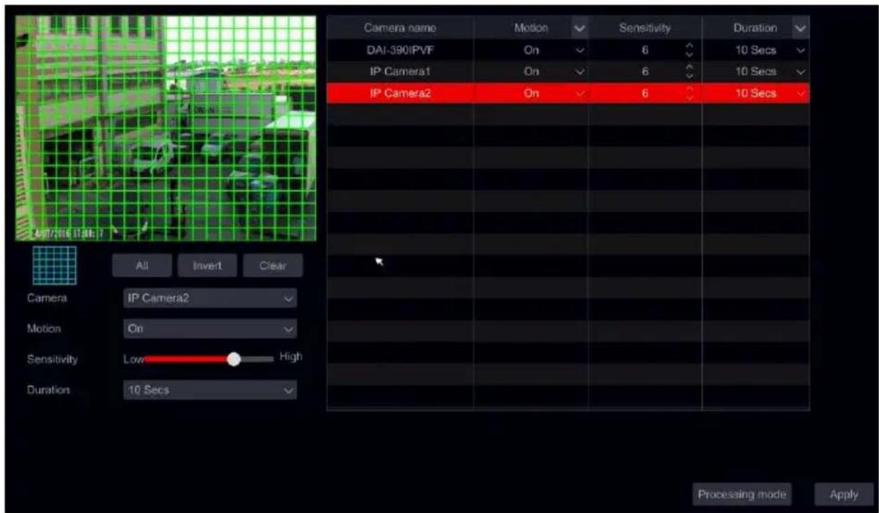
text_image
Camera name Motion Sensitivity Duration DAI-390IPVF On 6 10 Secs IP Camera1 On 6 10 Secs IP Camera2 On 6 10 Secs All Invert Clear Camera IP Camera2 Motion On Sensitivity Low High Duration 10 Secs Processing mode Apply② Select the camera, enable the motion and set the sensitivity and duration of the alarm. Sensitivity: the higher the value is, the more sensitive it is to motion. You should adjust the value according to the practical conditions since the sensitivity is influenced by color and time (day or night).
Duration: it refers to the interval time between two motion detections. For instance, if the duration time is set to 10 seconds, once the system detects a motion, it will trigger the alarm and disregard all other motions for 10 seconds (specific to camera). If there is another motion detected during this period, it will be considered as continuous movement, otherwise it will be considered as a single motion.
③ To select the area of interest, click and drag the mouse cursor on camera image from the top left to the bottom right. You can set more than one motion area. Click “All” to set the whole camera image as the motion detection area. Click “Reverse” to swap the selected area and the unselected area. Click “Clear” to clear all the motion areas. To delete a specified area click and drag the mouse cursor on the camera image from the bottom right to the top left.
④ Click “Apply” to save the settings. Click “Processing Mode” to go to the alarm handling configuration interface of the motion alarm.
9.2.2 Motion Alarm Handling Configuration
① Click Start→Settings→Alarm→Motion Alarm to access the following interface.
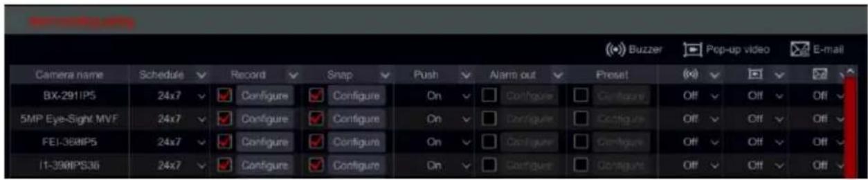
text_image
Buzzer Pop-up video E-mail Camera name Schedule Record Snap Push Alarm out Preset (B) (F) (G) (H) (B) (BX-291IPS 24x7 Configure Configure On Configure Configure Off Off Off 5MP Eye-Sight MVF 24x7 Configure Configure On Configure Configure Off Off Off FEI-388MP5 24x7 Configure Configure On Configure Configure Off Off Off I1-39MIPS36 24x7 Configure Configure On Configure Configure Off Off Off② Mark the and configure the desired response for motion alarm out of “Record”, “Snap”, “Push”, “Alarm-out” and “Preset”, and enable/disable “Buzzer”, “Pop-up Video”, “Pop-up Message Box” and “E-mail”. The alarm handling setting of motion alarm is similar to that of the sensor alarm (see 9.1 Sensor Alarm for details).
③ Click “Apply” to save the settings. You can click “Motion Settings” to return to the motion configuration interface.
9.3 Analytics Configuration
In NVRs and Hybrid DVRs IP Channels, Analytics are applicable only when supported by the IPC.
In DVRs running Ossia v1.3.x and up Sterile area and Line Crossing analytics are supported on analog cameras as well.
① Click Start→Settings→Camera→Analytics to access the interface.
② There are several types of Analytics alarms. You will need to configure the ones that applies to your needs. Select the camera, and choose the type of analytics you wish to set.
Note: Camera Tampering can be enabled in all conditions, but only one of "Object Monitoring", "Sterile area" "Line crossing" and "Face Detection" can be enabled in a given time.
9.3.1 Object Monitoring Configuration (IPC Channels Only)
Object monitoring will check that no items were left behind in a specified area (Left Object) or check that a monitored item was not taken (Missing Object)
① Click Start→Settings→Alarm→Analytics→Object monitoring (Must be supported by the IP Camera) to access the following interface.
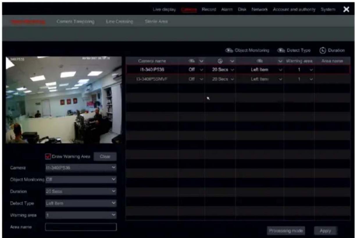
text_image
Live display Camera Record Alarm Disk Network Account and authority System Camera Tampering Live Crossing Stereo Area Object Monitoring Detect Type Duration 340IP518 2000/01/2019 Camera name Off 20 Secs Left Item 1 11-340IP536 Off 20 Secs Left Item 1 10-340IP55MVF Off 20 Secs Left Item 1 Draw Warning Area Clear Camera 11-340IP536 Object Monitoring Off Duration 20 Secs Detect Type Left Item Warning area 1 Area name Processing mode Apply② Choose the camera.
③ Enable/Disable the alarm.
④ Set the Duration for detection (5sec-2mins)
⑤ Choose the type of detection:
a) Missing object will monitor a specific object to prevent it from being taken. b) Left object will monitor an area to prevent from items to be left over.
⑥ Set the warning area. Up to 4 areas can be configured.
⑦ On the left side of the interface tick “Draw warning area” and create a polygon by clicking on the corners of the area you wish to mark. If you chose “missing object” then the polygon should be marked around a specific object. If you chose “left object” then the polygon should be marked around the monitored area.
⑧ Set the area's name.
⑨ If you need to set additional areas, switch to area 2-4 and repeat stages 3-8
9.3.2 Camera Tampering Configuration (IPC Channels Only)
Camera tampering will check that the camera hasn't been tampered in a way that will prevent it from providing a decent video image. The monitoring is divided into 3:
1) Camera Shifting: In case the camera was shifted and it does not point at the area that was set during the installation.
2) Lens Tampering: In case the Zoom/Focus of the lens was tampered and the image became blurry.
3) Camera Masking: In case that the camera was covered or blocked by a foreign object that blocks the majority of its view.
① Click Start→Settings→Alarm→Analytics→Camera Tampering (Must be supported by the IP Camera) to access the following interface.
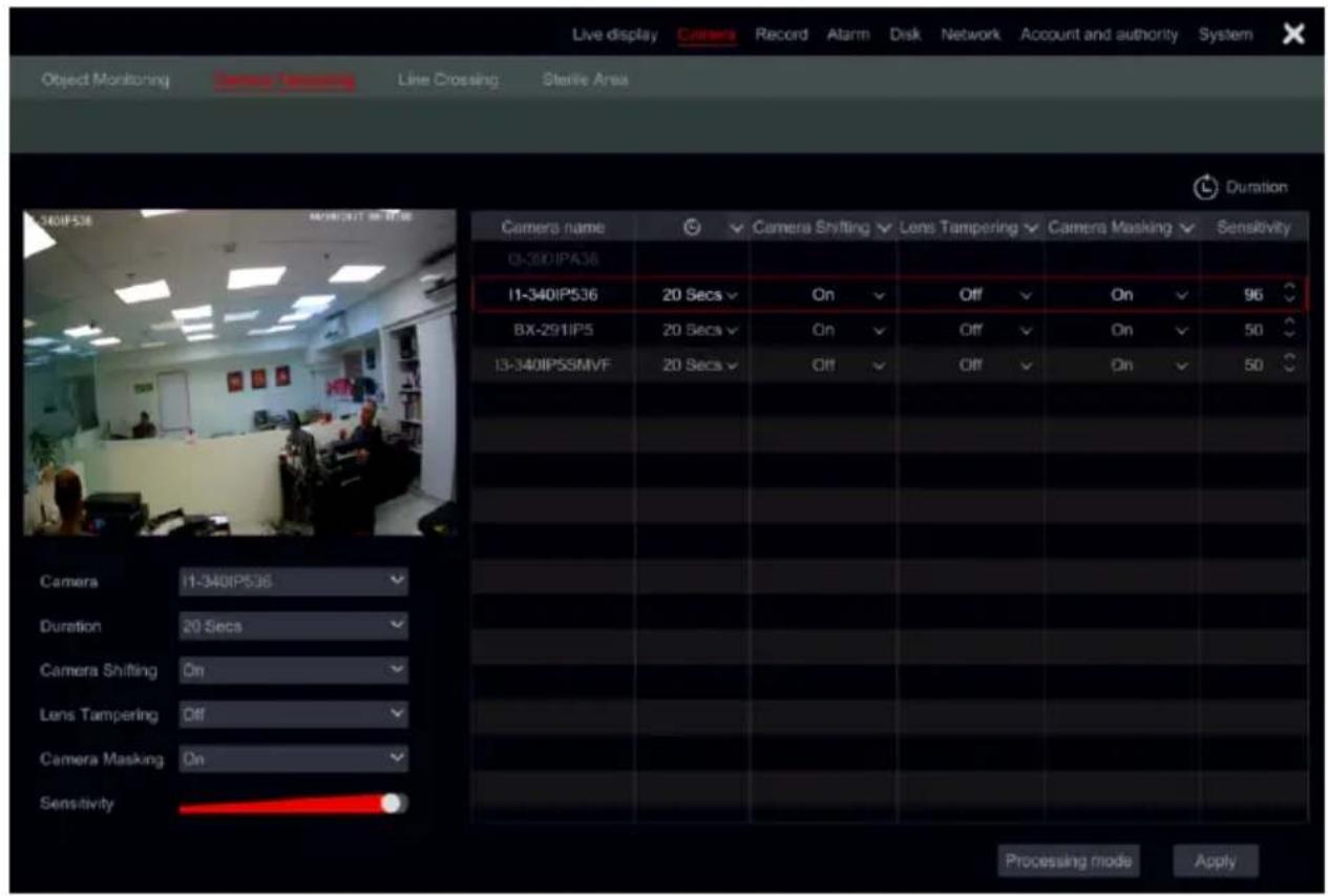
text_image
Live display Camera Record Alarm Disk Network Account and authority System Object Monitoring Camera Sensing Line Crossing Stertile Area Duration Camera name Camera Shifting Lens Tampering Camera Masking Sensitivity 0-340IP536 11-340IP536 20 Secs On Off On 96 BX-291IP5 20 Secs On Off On 50 13-340IPSSMVF 20 Secs Off Off On 50 Camera 11-340IP536 Duration 20 Secs Camera Shifting On Lens Tampering Off Camera Masking On Sensitivity Processing mode Apply② Choose the camera.
③ Set the Duration for detection (5sec-2mins)
④ Enable/Disable the required alarms.
⑤ Set the sensitivity.
⑥ If you need to set additional camera repeat stages 2-5
9.3.3 Line Crossing Configuration
Line crossing will detect any object that will fully cross a specified line. In Hybrid DVRs analog channels, the line crossing is only Bi-Directional (A↔→B). Line crossing monitoring generated by an IPC can work in 3 ways:
1) Left to Right (A→B)
2) Right to Left (B→A)
3) Any side to the other side (A←→B)
① Click Start→Settings→Alarm→Analytics→Line Crossing (Must be supported by the device) to access the following interface.
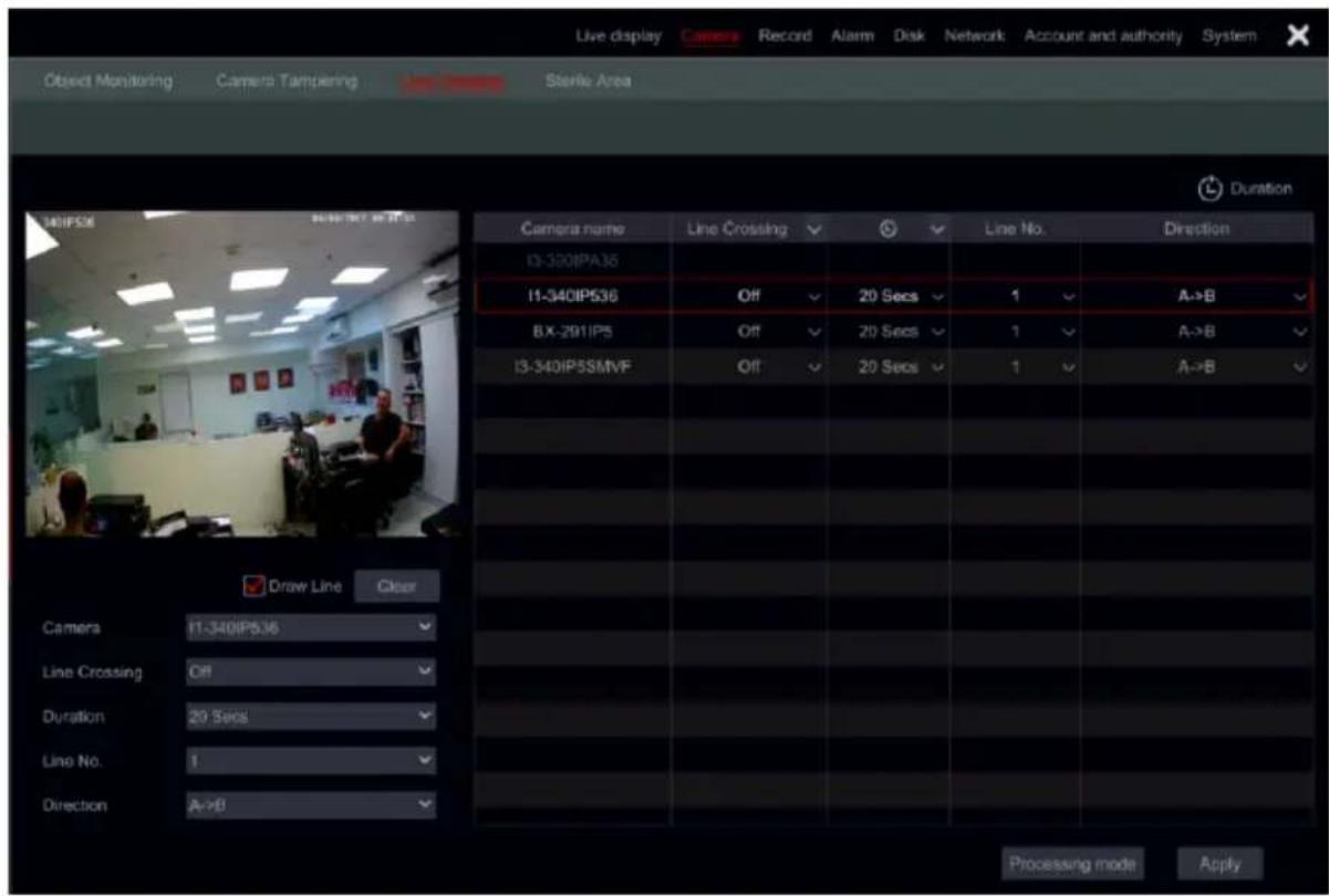
text_image
Live display Camera Record Alarm Disk Network Account and authority System Object Monitoring Camera Tampening Line Camera Sterile Area Duration M01PS36 Camera name Line Crossing Line No. Direction I3-300IPA36 I1-340IP536 Off 20 Secs 1 A→B BX-291IPS Off 20 Secs 1 A→B I3-340IP5SMVF Off 20 Secs 1 A→B Draw Line Clear Camera I1-340IP536 Line Crossing Off Duration 20 Secs Line No. 1 Direction A→B Processing mode Apply② Choose the camera.
③ Enable/Disable the alarm.
④ Set the Duration for detection (5sec-2mins)
⑤ Set the alert line. Up to 4 lines can be configured.
⑥ On the left side of the interface tick “Draw line” and create line by clicking and dragging the mouse cursor on the image.
⑦ Set the detection direction as specified on the line.
⑧ If you need to set additional lines, switch to line 2-4 and repeat stages 3-7
9.3.4 Sterile Area Configuration
Sterile area is an area which needs to be cleared from any object. Any object that will enter to the sterile area will trigger an alarm
① Click Start→Settings→Alarm→Analytics→Sterile Area (Must be supported by the device) to access the following interface.
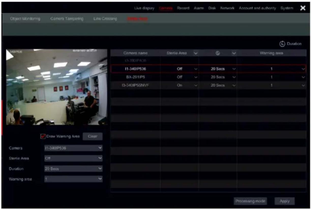
text_image
Live display Camera Record Alarm Disk Network Account and authority System Object Monitoring Camera Tampering Line Crossing Duration 140IP536 B/B/287 & B/287 Camers name Sterile Area Warning area I3-340IP536 Off 20 Secs 1 I1-340IP536 Off 20 Secs 1 BX-291IP5 Off 20 Secs 1 I3-340IP5SMVF On 20 Secs 1 Draw Warning Area Clear Camera I1-340IP536 Sterile Area Off Duration 20 Secs Warning area 1 Proceusing mode Apply② Choose the camera.
③ Enable/Disable the alarm.
④ Set the Duration for detection (5sec-2mins)
⑤ Set the warning area. Up to 4 areas can be configured.
⑥ On the left side of the interface tick “Draw warning area” and create a polygon by clicking on the corners of the area you wish to mark.
⑦ If you need to set additional areas, switch to area 2-4 and repeat stages 3-6
9.3.5 Analytics Alarm Handling Configuration
④ Click Start→Settings→Alarm→Analytics Alarm to access the following interface.
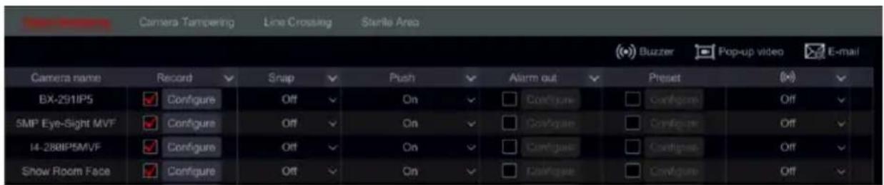
text_image
Camera Tampering Line Crossing Sterile Area Buzzer Pop-up video E-mail Camera name Record Snap Push Alarm out Preset (B) BX-291IP5 Configure Off On Configure Configure Off 5MP Eye-Sight MVF Configure Off On Configure Configure Off I4-280IP5MVF Configure Off On Configure Configure Off Show Room Face Configure Off On Configure Configure Off⑤ Mark the and configure the desired response for each of the analytics alarm out of “Snap”, “Alarm-out” and “Preset”, and enable/disable “Buzzer”, “Pop-up Video”, “Pop-up Message Box” and “E-mail”. The alarm handling setting of analytics alarm is similar to that of the sensor alarm (see 9.1 Sensor Alarm for details).
⑥ Click “Apply” to save the settings.
Note: You need to set the response for each of the analytics alarm separately. Failing to do so will result in insufficient system responses.
9.4 General Fault Alarms
9.4.1 General Fault Handling Settings
The system monitors its general health and the general condition of the HDD and network connection. The available alarms in this sector are: IP address conflict, Disk I/O error, Disk full, No disk, Illegal access, Network disconnected, HDD removed.
① Click Start→Settings→Alarm→General Faults Handling Settings
② Mark the and configure the desired response for General fault alarms out of “Push” for push notification, “Alarm-out” for I/O output. Enable/disable “Buzzer”, “Pop-up Message Box” and “E-mail”.
③ Click “Apply” to save the settings.
| Event type | Push | ✓ | Alarm out | ✓ | (×) | ✓ | A1 | ✓ | ☒ | ✓ |
| IP address conflict | On | ✓ | ☐ Configure | On | ✓ | On | ✓ | Off | ||
| Disk IO error | On | ✓ | ☐ Configure | On | ✓ | On | ✓ | Off | ✓ | |
| Disk full | On | ✓ | ☐ Configure | On | ✓ | On | ✓ | Off | ✓ | |
| No Disk | On | ✓ | ☐ Configure | On | ✓ | On | ✓ | Off | ✓ | |
| Illegal access | On | ✓ | ☐ Configure | On | ✓ | On | ✓ | Off | ✓ | |
| Network disconnected. | On | ✓ | ☐ Configure | On | ✓ | On | ✓ | Off | ||
| HDD was removed | On | ✓ | ☐ Configure | On | ✓ | On | ✓ | Off | ✓ | |
| RAID Exception | On | ✓ | ☐ Configure | Off | ✓ | Off | ✓ | Off | ✓ |
9.4.2 IPC Offline Settings
① Click Start→Settings→Alarm→General Faults→IPC Offline Settings to open the interface shown below.

text_image
Buzzer Pop-up video Pop-up message box E-mail Camera name Snap Push Alarm out Preset (M) Off Off Or BX-2911P5 Configure On Configure Configure Off Off Or 5MP Eye-Sight MVF Configure On Configure Configure Off Off Or FEI-368IP5 Configure On Configure Configure Off Off Or I1-398IPS36 Configure On Configure Configure Off Off Or② Mark the and configure the desired response for IPC Offline Alarm out of “Push”, “Record”, “Snap”, “Alarm-out” and “Preset”, and enable/disable “Buzzer”, “Pop-up Video”, “Pop-up Message Box” and “E-mail”. The IPC Offline Settings are similar to that of the sensor
alarm (see 9.1 Sensor Alarm for details).
③ Click “Apply” to save the settings.
9.5 Face Alarm
9.5.1 Face Detection
The system will trigger an alarm upon a detection of any face by the face detection cameras. Please note that the alarm is note relate to recognition, but to detection.
① Click Start→Settings→Alarm→Face Alarm→Face Detection to open the interface shown below.
| Camera name | Record | ✓ | Snap | ✓ | Push | ✓ | Alarm out | ✓ | Preset | (+) | ✓ |
| i4 face | ✓ | Configure | Off | ✓ | On | ✓ | Configure | Configure | Off | ||
| 2nd Floor | ✓ | Configure | Off | ✓ | On | ✓ | Configure | Configure | Off | ||
| Sales Office | ✓ | Configure | Off | ✓ | On | ✓ | Configure | Configure | Off | ||
| Main Passage | ✓ | Configure | Off | ✓ | On | ✓ | Configure | Configure | Off |
② Mark the and configure the face detection desired response for each of the supporting channels out of “Push”, “Record”, “Snap”, “Alarm-out” and “Preset”, and enable/disable “Buzzer”, “Pop-up Video”
9.5.2 Face Match Parameters
The face match parameters is in direct relation with the next configuration - Face Match. It
defines which cameras are allowed to trigger a response (Channel Settings) and under which condition (Similarity Settings.
① Click Start→Settings→Alarm→Face Alarm→Face Match Parameters to open the interface.
② Set the similarity settings. In this case, the similarity settings mean that if the detection similarity is lower than the setting, the set action will not be triggers and vice versa.
③ Set the Channel Settings. This defines which cameras are allowed to trigger a response in case of a recognition under the efficient similarity settings.
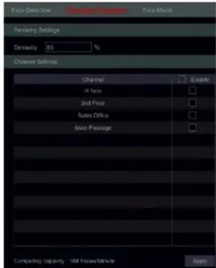
text_image
Face Detection Face Match Similarity Settings Similarity: 85 % Channel Settings Channel At face 2nd Floor Sales Office Main Passage Enable Computing capacity: 368 Faces/Minute Apply9.5.3 Face Match
The face match settings is the response for a face recognition under the settings of the “Face Match Parameters”.
① Click Start→Settings→Alarm→Face Alarm→Face Match to open the interface.

text_image
Buzzer Pop-up video E-mail Event type Enable Record Snap Push Alarm out Off Off On On Allow List1 On Configure Configure Configure Configure Configure Configure Configure Configure Configure Configure Block List On Configure Configure Configure Configure Configure Configure Configure Configure Configure Configure Configure Configure Configure Configure Configure Configure Configure Configure Configure Configure Configure Configure Configure Configure Configure Configure Configure Configure Configure Configure Configure Configure Configure Configure Configure Configure Configure Configure Configure Configure Configure Configure Configure Configure Configure Configure Configure Configure Configure Configure Infrastructure② Mark the and configure the response for each of the face database groups. Note that there is a “Stranger” group that is not defined in the database. All the unknown people falls into this group. The supported system responses are “Push”, “Record”, “Snap”, “Alarm-out” and “Preset”, and enable/disable “Buzzer”, “Pop-up Video”, “Pop up message” and “Send E-Mail”.
9.6 Alarm Event Notification
9.6.1 Alarm-out
Ossia devices will integrate with any device that has alarm output and display it on the alarm out list (together with any integral alarm outputs available on the device itself).
① Click Start→Settings→Alarm→Alarm Out to access the following interface.
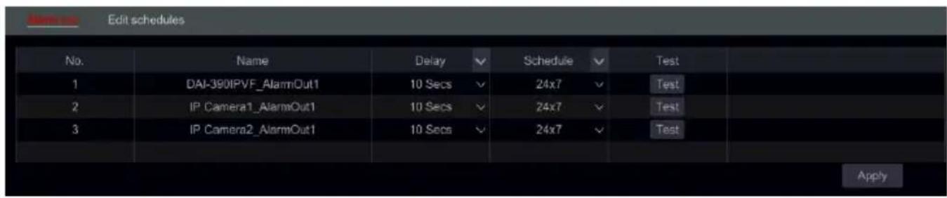
text_image
No. Name Delay Schedule Test 1 DAI-390IPVF_AlarmOut1 10 Secs 24x7 Test 2 IP Camera1_AlarmOut1 10 Secs 24x7 Test 3 IP Camera2_AlarmOut1 10 Secs 24x7 Test Apply② Set the delay time and the schedule of each alarm-out. You access the “Edit Schedules” interface from here (see 7.3.1 Add Schedule for details).
③ Click “Apply” to save the settings. You can click “Test” to test the alarm output.
9.6.2 E-mail
Click Start→Settings→Alarm→Event Notification→E-mail to go to the e-mail configuration interface. See 11.1.4 E-mail Configuration for details.
9.6.3 Display
Click Start→Settings→Alarm→Event
Notification→Display to set the duration of the pop-up video and pop-up message box. Click "Apply" to save the settings.
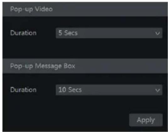
text_image
Pop-up Video Duration 5 Secs Pop-up Message Box Duration 10 Secs Apply9.6.4 Buzzer
Click Start→Settings→Alarm→Event Notification→Buzzer to set the holding time of the buzzer and click “Apply” to save the setting. You can click “Test” to test the buzzer.
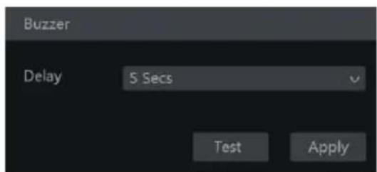
text_image
Buzzer Delay 5 Secs Test Apply9.6.5 Push Message
Click Start→Settings→Alarm→Event Notification→Push Message. Enable the push message service and wait for the Push server status to change from “Disabled” to xxx.xxx.xxx.xxx:xxxx
(Online). The IP Address of the Push server might vary according to your location and the availability of the server. All of the Push notification configuration will be done on your mobile phone through the “Provision Cam2” App. You can also set the “Push Schedule” which will define the days and times that push notifications will be sent by the device to the mobile app.
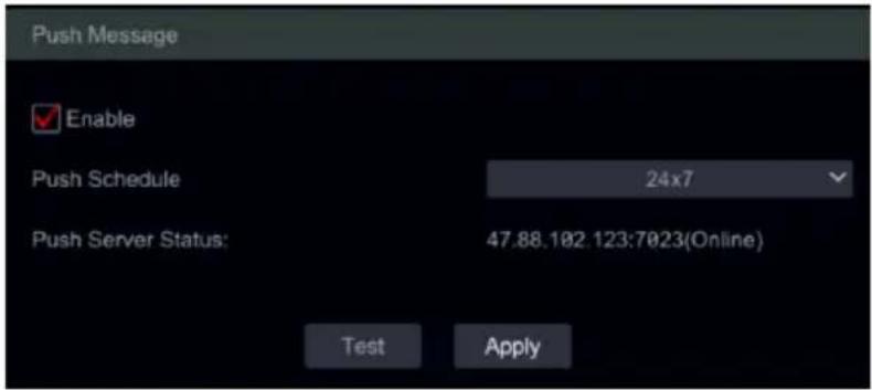
text_image
Push Message Enable Push Schedule 24x7 Push Server Status: 47.88.102.123:7023(Online) Test Apply9.7 Manual Alarm
Click the general tool bar at the bottom of the live-view interface to open the window as shown below. Click “Trigger” to start alarm. Click “Clear” to stop alarm. (The device must support alarms or have IPC which support alarm out connected to it in order to support this feature). If you wish for the alarm to be cleared automatically, set the delay timer according to your needs. “Manual” settings means that the alarm will stay active until you will clear it.
| Alarm-out name | Status | Trigger | Delay | Clear | |
| BX-291IP5_AlarmOut1 | Normal | Trigger | 5 Secs | ✓ | Clear |
| Video Server_AlarmOut1 | Normal | Trigger | 5 Secs | ✓ | Clear |
| I3-340IP5SMVF_AlarmOut1 | Normal | Trigger | 5 Secs | ✓ | Clear |
9.8 View Alarm Status
Click Start→Settings→Alarm→Alarm Status or click 📄 on the general tool bar at the bottom of the live-view interface and click “Alarm Status”.
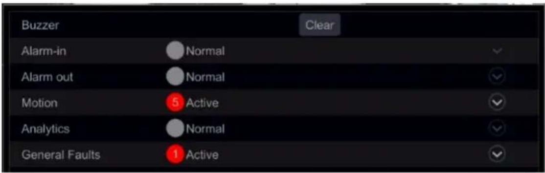
text_image
Buzzer Clear Alarm-in Normal Alarm out Normal Motion 5 Active Analytics Normal General Faults 1 ActiveClick “Clear” button to stop the buzzer if the buzzer is on. Click ▼ to view detailed information as shown below.
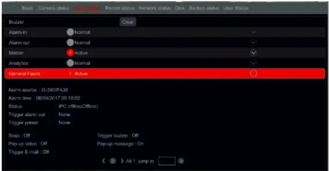
text_image
Basic Camers status Record status Record status : Network status Disk Backup status User Status Buzzer Clear Alarm-in Normal Alarm out Normal Motion Active Analytics Normal General Faults 1 Active Alarm source : I3-390IPA36 Alarm time : 06/08/2017 09:58:02 Status : IPC offline(Offline) Trigger alarm out : None Trigger preset : None Snap : Off Trigger buzzer : Off Pop-up video : Off Pop-up message : On Trigger E-mail : Off < > All 1, jump toIf the exception information is more than one page, you can input the number in the box and click ➤ to jump to the specified page. Click ◀ / ➤ to view the exception alarm information in the previous/next pages. Click ➤ to play the alarm record (if available).
10 Account & Permission Management
10.1 Account Management
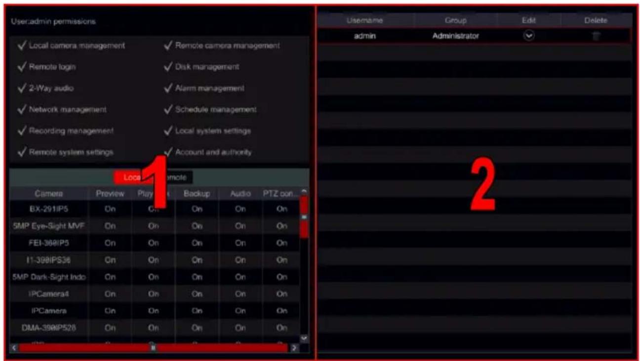
text_image
Useradmin permissions ✓ Local camera management ✓ Remote camera management ✓ Remote login ✓ Disk management ✓ 2-Way audio ✓ Alarm management ✓ Network management ✓ Schedule management ✓ Recording management ✓ Local system settings ✓ Remote system settings ✓ Account and authority Local Remote Camera Preview Play Backup Audio PTZ con BX-291IP5 On On On On On 5MP Eye-Sight MVF On On On On On FEI-388IP5 On On On On On I1-398IPS36 On On On On On 5MP Dark-Sight Indo On On On On On IPCamera4 On On On On On IPCamera On On On On On DMA-398IP528 On On On On 2Click Start→Settings→Account and Authority→Account→Edit User
Area ① displays the user permissions. Area ② displays the user list. Click on a user in area ② to display its user permissions in area ①.
There are three default permission groups (“Administrator”, “Advanced” and “Ordinary”) available when adding accounts. You can manually add new permission group (see 10.3.1 Add Permission Group for details).
The user admin have all system permissions and it can manage the device's accounts. Group "Administrator" owns all the permissions displayed in area ① and its permissions can never be changed or edited while the permissions of "Advanced" and "Ordinary" can be changed.
10.1.1 Add User
① Click Start → Settings → Account and Authority → Account → Add User or click + beside the search box.
② Set the username, password and permission group. Try to choose a complicated password that will be hard to guess. It is optional to set the e-mail address and pattern lock. You can also set if the user is allowed to change his password. Click “Add” to confirm and add the user.
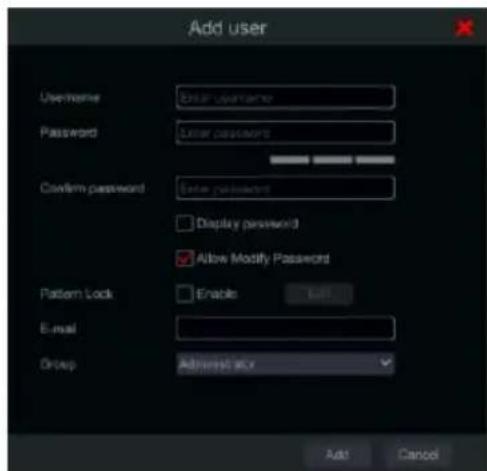
text_image
Add user Username: Password: Confirm password: Display password Allow Modify Password Pattern Lock Enable Add E-mail Group: Added size Add Cancel10.1.2 Edit User
Click Start→Settings→Account and Authority→Account→Edit User. Click in the user list or double click the user to edit its information. Click to delete the user (the user admin cannot be deleted).
➢ Edit Security Question
You can set password security question only for admin. Click “Edit Security Question” and set questions and answers in the opened window. If you forget the password, please refer to Q4 in Appendix A FAQ.
Modify Password
Only the password of admin can be modified. Click “Modify Password”. Input the current password and set new password. Click “OK” to save the settings.
▶ Recover Password
Click "Recover Password" to reset the password to 123456.
Edit User
Click “Edit User” to open the window as shown below. If admin is edited, its permission control is closed and permission group cannot be changed. You can enable or disable other users (if disabled, the user will be invalid), open or close their permission control (if closed, the user will get all the permissions which the administrator permission group has) and set their permission groups. Click “OK” to save the settings.
10.2 User Login & Logout
Login: Click Start→Login or directly click the live-view interface, then input the username and the password. Click “Login” button to log in the system. If “Auto Login” is marked – the system will not ask for password again until logout.
Logout: Click Start→Logout or click Start→Shutdown. Select “Logout” in the window and click “OK” button to log out the system.
10.3 Permission Management
10.3.1 Add Permission Group
Click Start→Settings→Account and Authority→Account→Edit Permission Group to open the interface as shown below.
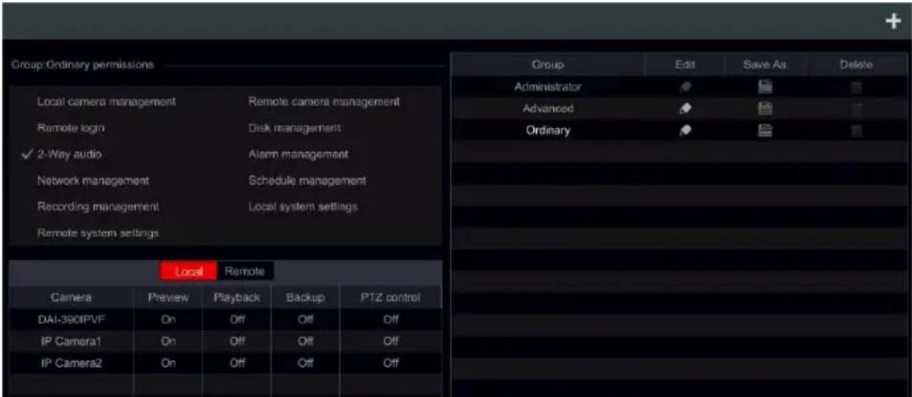
text_image
Group: Ordinary permissions Local camera management Remote camera management Remote login Disk management ✓ 2-Way audio Alarm management Network management Schedule management Recording management Local system settings Remote system settings Local Remote Camera Preview Playback Backup PTZ control DAI-380IPVF On Off Off Off IP Camera1 On Off Off Off IP Camera2 On Off Off Off Group Edit Save As Delete Administrator Advanced Ordinary OrdinaryClick + add a permission group. Set the group name, mark the permissions as required and set the specific "Local" and "Remote" permissions. Click "Add" to save the settings.
10.3.2 Edit Permission Group
Go to “Edit Permission Group” interface and click the group list to edit the permission group (the operations of the “Edit Permission Group” are similar to that of the “Add Permission Group”, please see 10.3.1 Add Permission Group). Click to save the group as another group. Click to delete the permission group. The three default permission groups (“Administrator”, “Advanced” and “Ordinary”) cannot be deleted.
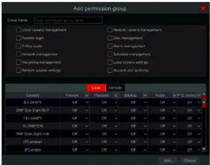
text_image
Add permission group Group name: Cross-permission group name Local camera management Remote login 2-Way audio Network management Recording management Remote system settings Remote camera management Disk management Alarms management Schedule management Local system settings Account and authority. Local Remote Camera Preview Playback Backup Audio PPTZ control B-X-291IPS Off Off Off Off Off Off Off SMP Eye-Sight MVF Off Off Off Off Off Off Off FEI-301MPS Off Off Off Off Off Off Off IFL-301MPS36 Off Off Off Off Off Off SMP Disk-Sight Inds Off Off Off Off Off Off IFC camera1 Off Off Off Off Off Off IFC camera2 Off Off Off Off Off Add Cancel10.4 Black and White List
① Click Start→Settings→Account and Authority→Security→Black and White Lists to go to the following interface.
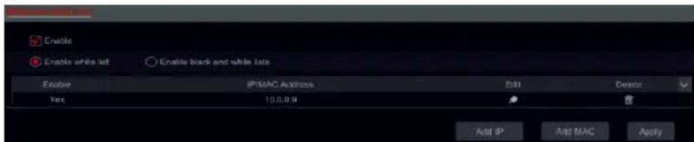
text_image
Enable Enable white list Enable black and white lists Enable IP-MAC Address Edit Delete Yes 10.0.0.9 Add IP Add MAC Apply② Check “Enable” and choose “Enable Allow List” or “Enable Block List” (the PC client of which the IP address is in the allow list can access device remotely while the PC client in the block list cannot).
③ Add IP/IP segment/MAC. Click “Add IP” or “Add MAC” button and check “Enable” in the popup window (only if you check it can the IP/IP segment/MAC you add be effective).
Enter the IP/IP segment/MAC and click “OK” button. In the above interface, click to edit IP/IP segment/MAC, click 📋 to delete it. Click “Apply” to save the settings.
10.5 Preview on Logout
Preview on logout configuration will set which channels will be available for view while no user is logged into the system only channels marked as “on” will be available. The default setting is “on” for all channels. To configure:
① Click Start→Settings→Account and Authority→Security→Preview on Logout to go to the following interface.
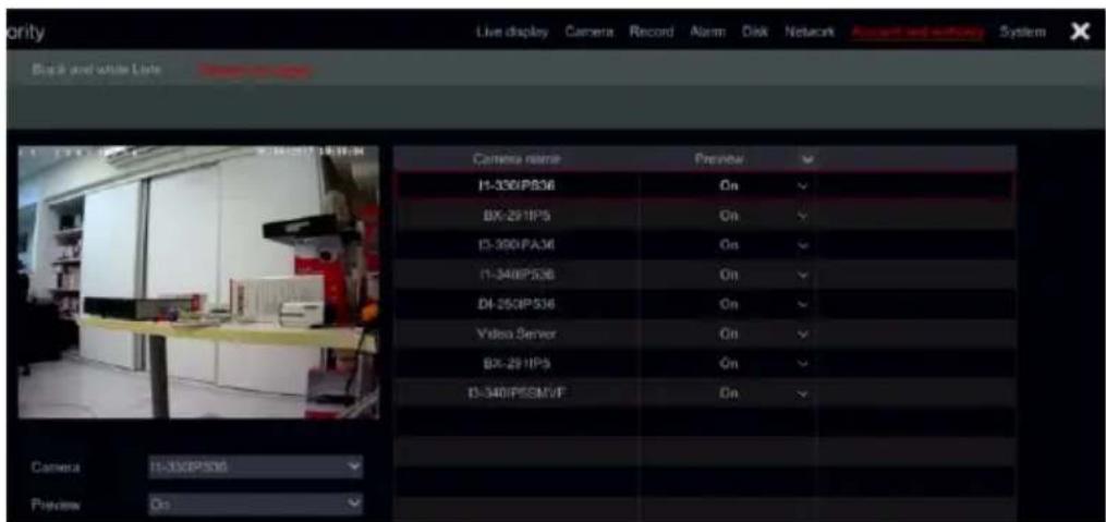
text_image
Live display Camera Record Alarm Disk Network Asset and security System File 2 and white lists Camera name Preview H-330IP536 On BX-291IP5 On I3-300PA36 On I1-340IP536 On DI-250IP536 On Video Server On BX-291IP5 On I3-340IPSSMVF On Camera I1-350P536 Preview On② Choose which channels can be viewed and which are not when all local users are logged out.
10.6 Password Security
Password security can force the user to change the password after given time and also can force the user to choose a password with defined strength
① Click Start→Settings→Account and Authority→Security→Password Security to go to the following interface.

text_image
Password security Level Strong Expiration Time 98Days External network access restrictions (administrators use the default password to preview only the field when it is logged in from the external network) Apply② Set the password level (Password with lower strength level will not be permitted)
③ Choose Expiration time out of: Never / 30 Days / 60 Days / 90 Days.
④ If you wish, you can tick “External network access restrictions”. This setting will allow you to use default credentials (admin/123456) but restrict to live view only when connecting from devices which are not in the LAN (Even for administrators).
10.7 User Status:
① Click Start→Settings→Account and Authority→User Status to go to the following interface.
② In the list you will find all the users who are currently connected to the system including their IP addresses and the number of live/playback channels they occupy
③ Click on 📄 to see detailed information about the channel usage by the selected user.
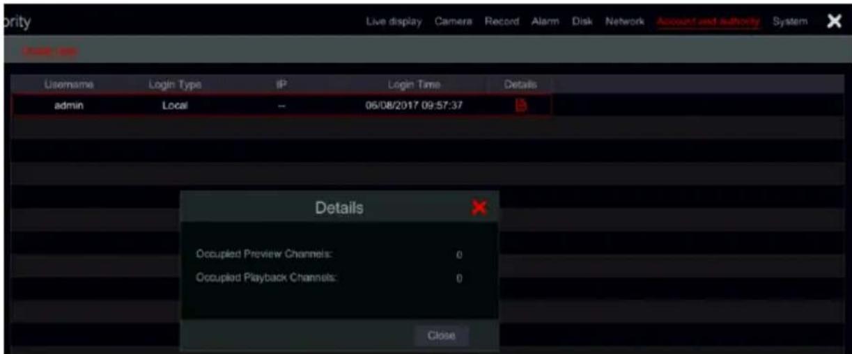
text_image
Welcome Username Login Type IP Login Time Details admin Local -- 06/08/2017 09:57:37 Details Occupied Preview Channels: 0 Occupied Playback Channels: 0 Close11 Device Management
11.1 Network Configuration
11.1.1 TCP/ IPv4/6 Configuration
IP Address Settings
Click Start→Settings→Network→TCP/ IPv4/6 to go to the following interface. Mark “Obtain an IP address automatically” and “Obtain DNS automatically” to get the IP address and DNS automatically, or input the IP address, subnet mask, gateway, preferred DNS and alternate DNS manually. Click “Apply” to save the settings. If your network support IPv6 you can set it here as well. The default setting is “Obtain an IPv6 address automatically”
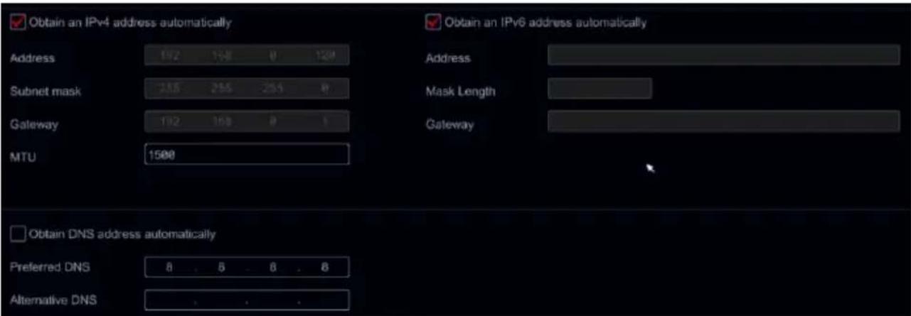
text_image
Obtain an IPv4 address automatically Address 192 158 0 120 Subnet mask 255 255 254 0 Gateway 192 158 0 1 MTU 1500 Obtain an IPv6 address automatically Address Mask Length Gateway Obtain DNS address automatically Preferred DNS 8 . 8 . 8 . 8 Alternative DNS . . . .Internal Ethernet Port Introduction:
If you use the PoE NVR, the network state of the internal ethernet ports will be shown on the interface. Refer to the picture below.
The internal ethernet port connects all the PoE ports with the NVR system. The PoE ports are available when the state is online. If it is offline, the NVR PoE ports will be unavailable. The IP address and subnet mask of the internal ethernet port can be changed in this interface (not recommended).
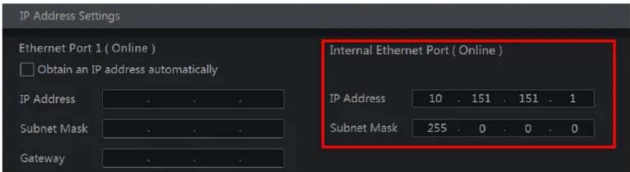
text_image
IP Address Settings Ethernet Port 1 ( Online ) Obtain an IP address automatically IP Address Subnet Mask Gateway Internal Ethernet Port ( Online ) IP Address 10 . 151 . 151 . 1 Subnet Mask 255 . 0 . 0 . 0▶ PPPoE Settings
In the above interface, mark “Enable” in “PPPoE Settings” and input the username and password. Click “Apply” to save the settings.
11.1.2 Port Configuration
Click Start→Settings→Network→Port. Input the HTTP, HTTPS, Server, RTSP and POS ports of the device and click “Apply” to save the settings.

text_image
Ports HTTP Port 80 HTTPS Port 443 Enable Server Port 6036 RTSP Port 554 Anonymous login allowed (No need for user name and password) POS Port 9036 ApplyHTTP Port: the default HTTP port of the device is 80. The port number can be changed. The port is mainly used for direct IE and mobile application remote access via static IP or DDNS. To access the device through IE, input the IP address plus HTTP port in the address bar for example: http://192.168.11.61:81. (If the HTTP port is 80 – there is no need to input it)
HTTPS Port: The default is 443 and must be enabled from this interface in order to use it. HTTPS will allow you to create an encrypted communication between the device and any web browser connected to it. Once enabled, you will be able to access the device using HTTPS address. For example: https://192.168.11.61. If you don't change the default port (443) there is no need to input it in the address line.
Server Port: the default server port of the device is 6036 and it can be changed as required. The port is mainly used in network video management system like CMS.
RTSP Port: RTSP (Real-Time Stream Protocol) can be used to retrieve the video stream from the device by any media player which supports the RTSP. You can view the live stream synchronously. The default RTSP port is 554. It can be changed as required. Here you can also tick “Watch video via anonymous login” to allow unauthenticated RTSP connections.
POS Port: POS (Point Of Sale) is used to connect cash registered to the device in order to compare the cash register output with the video recordings. The default port is 9036.
Note: The HTTP / HTTPS ports and server port of the device should be mapped to the router before you access the device via WAN.
11.1.3 DDNS Configuration
The DDNS is used to control the dynamic IP address through a domain name. You can access to the device easily if the DDNS is enabled and properly configured.
Click Start→Settings→Network→DDNS to go to the interface as shown below.
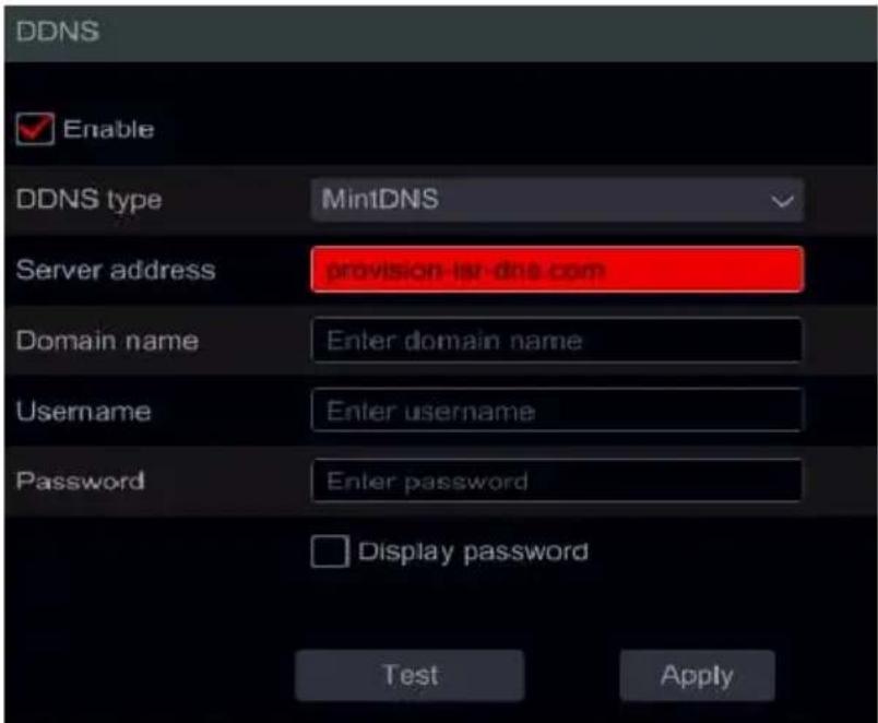
text_image
DDNS Enable DDNS type MintDNS Server address provision-lst-dns.com Domain name Enter domain name Username Enter username Password Enter password Display password Test ApplyMark “Enable” and select the DDNS type. Input the server address, domain name, username and password according to the selected DDNS type. Click “Test” to test the confirm connectivity. Click “Apply” to save the settings.
You will have to input the server address and domain name for some DDNS types. Go to the relative DNS website to register domain name and input the registered domain information here).
We will take http://provision-ISR-dns.com for example:
① Input http://provision-ISR-dns.com in the IE address bar to the website.
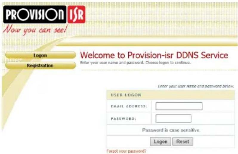
text_image
PROVISION ISR Now you can see! Logon Registration Welcome to Provision-isr DDNS Service Enter your user name and password. Choose logon to continue. Enter your user name and password below. USER LOGON EMAIL ADDRESS: PASSWORD: Password is case sensitive. Logon Reset Forgot your password?② Click Registration button to go to the interface as shown below. Set the DDNS account information (username, password, Etc.) and click Submit button to save the account.
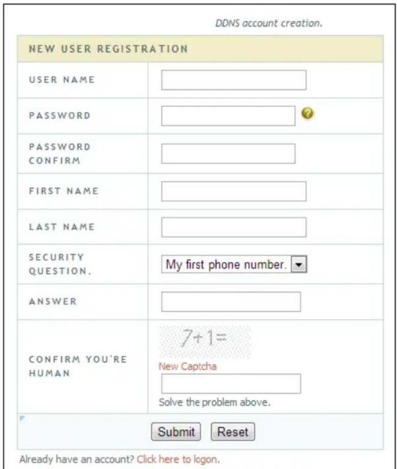
text_image
DDNS account creation. NEW USER REGISTRATION USER NAME PASSWORD PASSWORD CONFIRM FIRST NAME LAST NAME SECURITY QUESTION. ANSWER CONFIRM YOU'RE HUMAN 7+1= New Captcha Solve the problem above. Submit Reset Already have an account? Click here to logon.③ Create domain name and click Request Domain.
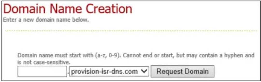
text_image
Domain Name Creation Enter a new domain name below. Domain name must start with (a-z, 0-9). Cannot end or start, but may contain a hyphen and is not case-sensitive. provision-ISR-dns.com ▼ Request Domain④ After you successfully request your domain name, you will see your domain name information.
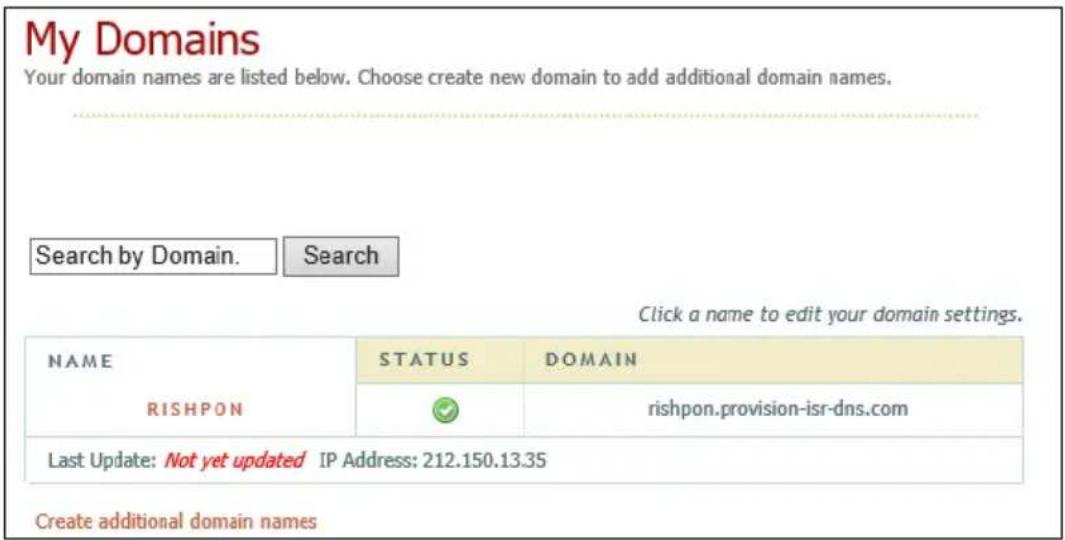
text_image
My Domains Your domain names are listed below. Choose create new domain to add additional domain names. Search by Domain. Search Click a name to edit your domain settings. NAME STATUS DOMAIN RISHPON ✓ rishpon.provision-ISR-dns.com Last Update: Not yet updated IP Address: 212.150.13.35 Create additional domain names⑤ Click Start→Settings→Network→DDNS. Enable the DDNS service and select MintDNS as the DDNS type. Input the pre-registered username, password and domain name and click “Apply”.
⑥ Map the IP address and HTTP port in the router (you can skip this step if UPnP function is enabled).
⑦ Input the registered domain name plus HTTP port like http://xx.provision-isl-dns.com:81 in the IE address bar and press the Enter key to go to the IE client.
11.1.4 E-mail Configuration
Click Start→Settings→Network→E-mail. Input the sender's e-mail address, name, password, SMTP server and SMTP port (you can click "Default" to reset the SMTP port to the default value) and enable/disable the SSL and "attaching image". Click "Test". Input the e-mail address of the recipient in the window and click "OK" button. The e-mail address of the sender will send an e-mail to the recipient. If the e-mail was sent successfully, it indicates that the e-mail address of the sender is configured correctly. Click "Apply" to save the settings.
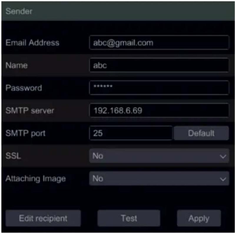
text_image
Sender Email Address abc@gmail.com Name abc Password ****** SMTP server 192.168.6.69 SMTP port 25 Default SSL No Attaching Image No Edit recipient Test ApplyClick "Edit Recipient" to open the following interface.
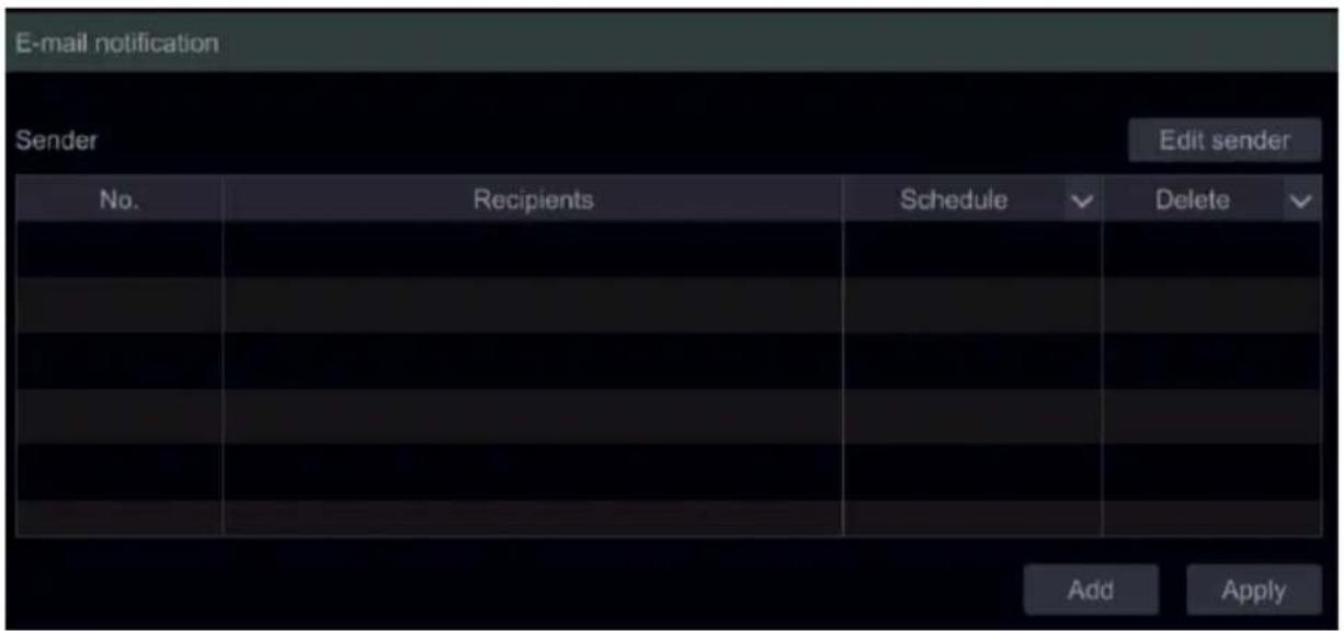
text_image
E-mail notification Sender Edit sender No. Recipients Schedule Delete Add ApplyClick “Add” and input the recipient’s e-mail address in the opened window. Set the schedule rule which you want to apply for the recipient and click “Add” to confirm. Click 📄 to delete a recipient from the list. Click “Apply” to save the settings. Click “Edit Sender” to go to the e-mail configuration interface of the sender.
11.1.5 UPnP Configuration
By using UPnP you can access the device through IE client in WAN via router without port mapping.
① Click Start→Settings→Network→UPnP to go to the following interface.
② Make sure the router supports UPnP function and the UPnP is enabled in the router.
③ Set the device's IP address, subnet mask and gateway and set the corresponding in the router interface.
④ Mark “Enable” and click “Apply” button.
Click “Refresh” button to refresh the UPnP status. If the UPnP status is still “Invalid UPnP” after refreshing, the port number is probably wrong. Please change the mapping type to “Manual” and click 📋 to modify the port until the UPnP status turns to “Valid UPnP”. Refer to the following picture. You can view the external IP address of the device. Input the external IP address plus port in the IE address bar to access the device.
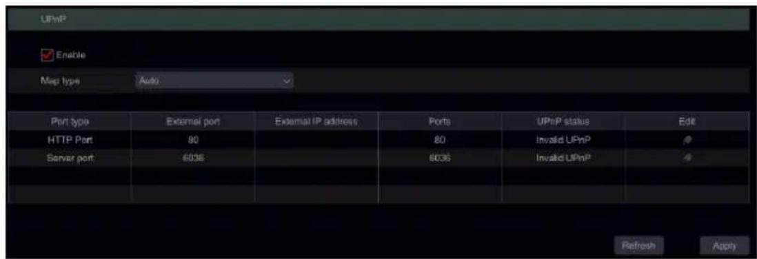
text_image
UPnP Enable Map type Auto Port type External port External IP address Ports UPnP status Edit HTTP Port 90 80 Invalid UPnP Server port 6036 6036 Invalid UPnP Refresh Apply11.1.6 NAT Configuration
NAT allows you to connect to the device using the P2P cloud platform. After enabling it, all you will have to do is to scan the QR code using the mobile app in order to remotely connect to your device.
Click Start→Settings→Network→NAT. Mark “Enable” and click “Apply” to save the settings.
11.1.7 FTP Configuration
FTP allows you to backup recording to an FTP server based on set rules. The data is uploaded to the FTP from the HDD and cannot replace the HDD or perform as a “fail safe” to the HDD.
① Click Start→Settings→Network→FTP.
② Enable the FPT in order to activate the interface.
③ Input the FTP server address and port (default port is 21)
④ Input the login credentials for the server.
⑤ Set the maximum file size (in MB)
⑥ Set the remote directory path on the FTP
⑦ Choose which alarms will trigger the device to upload information to the FTP server and set the stream type (Main/Sub) and if to include snapshot.
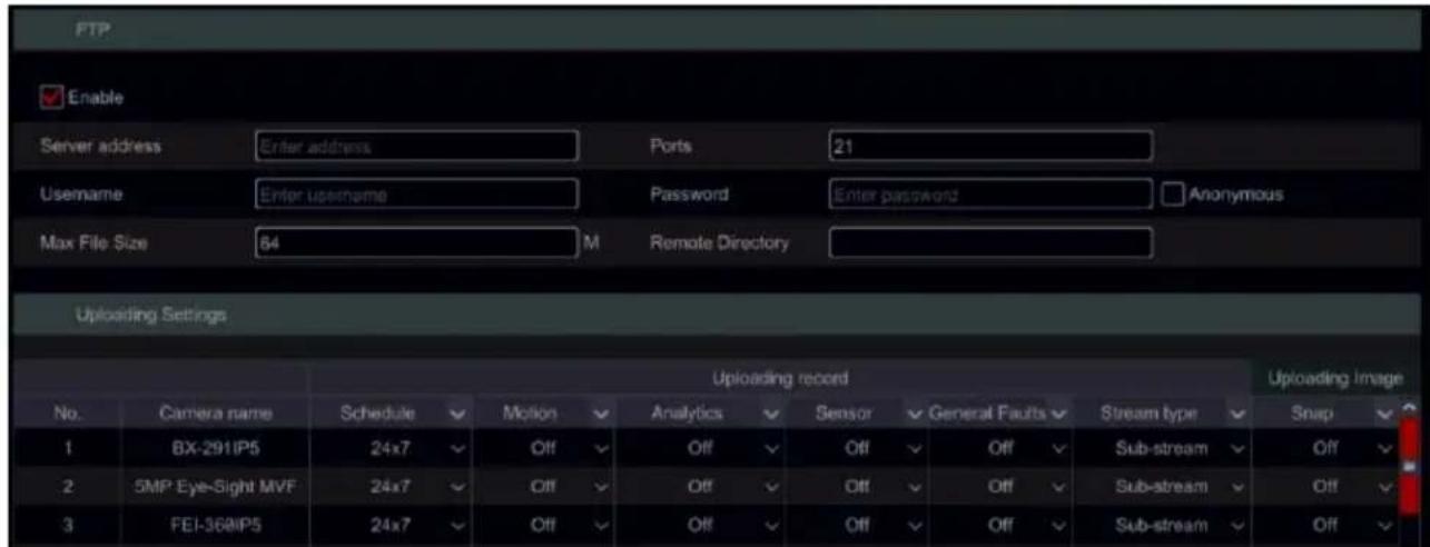
text_image
FTP Enable Server address Enter address Ports 21 Username Enter username Password Enter password Anonymous Max File Size 84 M Remote Directory Uploading Settings No. Camera name Schedule Motion Analytics Sensor General Faults Stream type Snap 1 BX-291IP5 24x7 Off Off Off Off Off Sub-stream Off 2 5MP Eye-Sight MVF 24x7 Off Off Off Off Sub-stream Off 3 FEI-36@IP5 24x7 Off Off Off Off Sub-stream Off⑧ Once done, click test. The system will confirm the connectivity and read/write permission on the FTP platform based on the given credentials.
⑨ If Test was successful, click "OK" to save.
⑩ If the test failed, repeat this process from stage 3 to 6.
11.1.8 SNMP Configuration
Simple Network Management Protocol (SNMP) is an Internet Standard protocol for collecting and organizing information about managed devices on IP networks and for modifying that information to change device behavior.
① Click Start→Settings→Network→SNMP
② Set all information required for SNMP. This information should be provided by the site IT manager, or configured on the supported device (Managed Switch/Router Etc.)
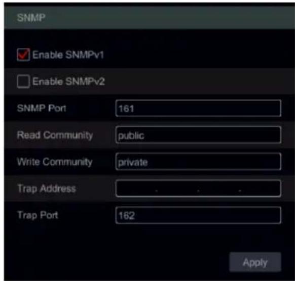
text_image
SNMP Enable SNMPv1 Enable SNMPv2 SNMP Port 161 Read Community public Write Community private Trap Address . . . . Trap Port 162 Apply11.1.9 View Network Status
Click Start→Settings→Network→Network Status to view the network status / or click 📄 on the general tool bar at the bottom of the live-view interface and switch to “Network Status” to view network status.
11.2 Basic Configuration
11.2.1 General Settings
Click Start→Settings→System→Basic→General Settings to go to the following interface. Set the device name, device No., language, video format and resolution. Enable or disable the configuration wizard, "Log In Automatically" or "Log Out Automatically" (if marked, you can set the wait time before log out). Click "Apply" to save the settings.
Device Name: The name of the device. It may display on the client end or CMS and help the user to easily recognize the device.
Device No.: An address number used for controlling the device using C06 Controller (Joystick)
Language: Language Selection Video Format: Two modes: PAL and NTSC. Select the video format according to the region / cameras.
Main Display: The device will automatically set the resolution when you turn on the device for the first time. If only VGA monitor is connected, the resolution will be set automatically to 1280x1024. If and HDMI monitor is connected, the resolution will be set automatically to 1920x1080. If both VGA and HDMI Monitors are connected, the HDMI will be the primary monitor and the resolution will be set to 1920x1080. In such case, you will have to reduce the resolution manually in case that the VGA monitor is not working well. Once the resolution has been set manually, the auto-configuration is disabled.
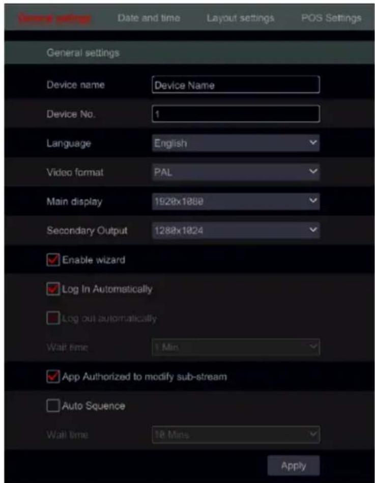
text_image
General settings Date and time Layout settings POS Settings General settings Device name Device Name Device No. 1 Language English Video format PAL Main display 1928x1000 Secondary Output 1288x1024 Enable wizard Log In Automatically Log out automatically Wait time 1 Min App Authorized to modify sub-stream Auto Sequence Wait time 16 Mins ApplySecondary Output (Devices with 2 HDMI outputs only): Set the output for the secondary video output.
Enable Wizard: Enabling the configuration wizard to pop-up on each startup of the system. Log in Automatically: The system will not request a login password until you will manually log out.
Log Out Automatically: The system will log out og the system after the configured time duration.
App Authorized to modify Sub-Stream : The system will prevent from “Provision Cam2” mobile app from making any changes to the main/sub stream resolutions. This will result in better performance on CMS and 3rd party applications on the expense of lower performance from the App side.
Auto Sequence + Wait Time: Start sequence when the system is not in use (mouse not moving) for a defined time.
11.2.2 Date and Time Configuration
Click Start→Settings→System→Basic→Date and Time to go to the interface as shown below. Set the system time, date format, time format and time zone of the device. If the selected time zone includes DST, the DST of the time zone will be marked by default. Click “Apply” to save the settings.
You can manually set the system time or synchronize system time with network through NTP.
Manual: select “Manual” in the “Auto Time Sync.” option and click 📋 after the “System Time” option to set the system time.
NTP: select “NTP” in the “Auto Time Sync.” option and input the NTP server. (The default is www.provisionisr-time.com)
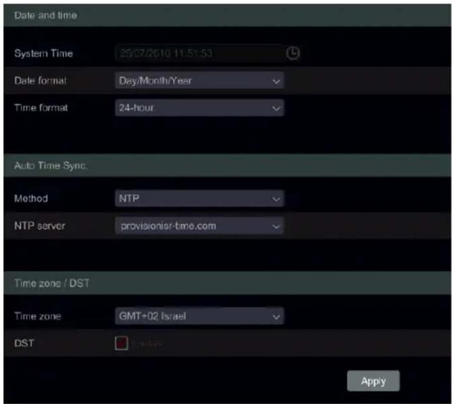
text_image
Date and time System Time 25/07/2019 11:51:53 Date format Day/Month/Year Time format 24-hour Auto Time Sync. Method NTP NTP server provisionisr-time.com Time zone / DST Time zone GMT+02 Israel DST Apply11.2.3 Layout settings:
Click Start→Settings→System→Basic→layout settings to go to the interface as shown below. The layout setting appearance and configuration options will be different depending on your device model. There are 3 options.
1) NVR/PoE NVR – you will have only “Main Display” option. Here you will be able to set the layout for sequence as described in section 5.3.2 Sequence or set your customized display modes as described in section 5.3.1 Display Presets.
2) DVR with Spot feature: You will find “Main display” as described above as well as “Output 2” which refers to the spot configuration. You will be able to set the display windows (Single channel only) and the dwell time in between windows. The spot output does not show the main interface.
3) Professional devices with 2 HDMI Outputs: In addition to the described above, you will also find here Secondary display. From here you will be able to set the layout for the second HDMI output. The secondary display does not show the main interface.
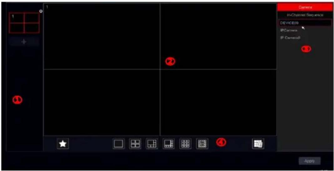
text_image
Camera in-Channel Sequence DEVICE09 IPCamera IP CameraB ApplyArea ① displays all the schemes; area ② shows the camera layout; area ③ displays all the cameras and groups; area ④ is the tool bar (☐: clear button; ★: favorite button, click it to save the layout as preset – only available for main display).
11.2.4 POS settings:
Click Start→Settings→System→Basic→POS to go to the interface as shown below.
POS is used to integrate between the recorded video and the information coming from a supporting cash register. This section allows you to configure the POS and link it to the proper video channel. Up to 4 POS can be configured.
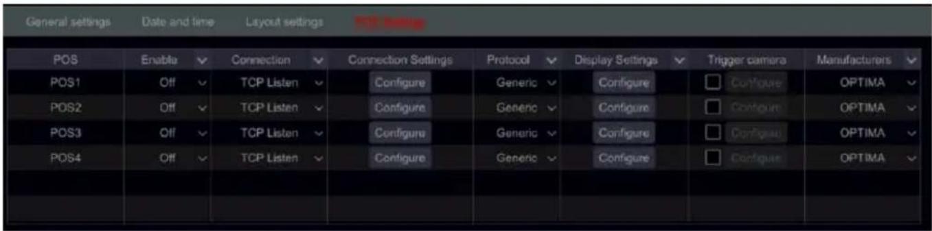
text_image
General settings Date and time Layout settings Post setting POS Enable Connection Connection Settings Protocol Display Settings Trigger camera Manufacturers POS1 Off TCP Listen Configure Generic Configure Configure OPTIMA POS2 Off TCP Listen Configure Generic Configure Configure OPTIMA POS3 Off TCP Listen Configure Generic Configure Configure OPTIMA POS4 Off TCP Listen Configure Generic Configure Configure OPTIMA1) Enable the required POS channel.
2) Set the Connection Type
3) Set the connection settings as follows:
a. POS IP: The IP of the required cash register.
b. If you wish, you can set filters for ports and destinations.
4) Set the POS protocol as required.
5) Set the display settings as follows:
a. Set the start and end characters
b. Set the new line character.
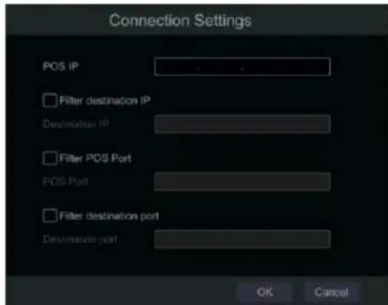
text_image
Connection Settings POS IP Filter destination IP Destination IP Filter POS Port POS Port Filter destination port Destination port OK Cancelc. Set "ignore" character.
d. Set connection timeout (Default is 10 seconds)
6) Switch to the "Display Position" Tab and set the required position for the text form the POS.
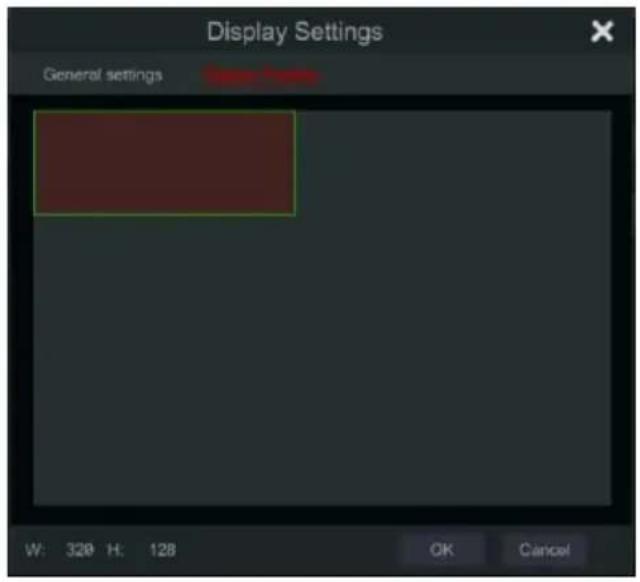
text_image
Display Settings General settings W: 320 H: 128 OK Cancel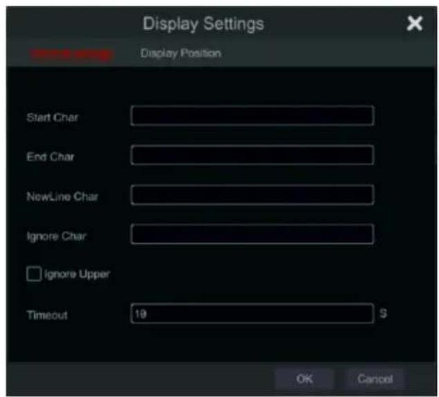
text_image
Display Settings Start Char End Char NewLine Char Ignore Char Ignore Upper Timeout 10 S OK Cancel7) If you wish for the POS to trigger a camera record, tick that option and set the camera(s) you wish to record.
8) Set the manufacturer of the POS.
11.3 Maintenance:
11.3.1 View Log
Click Start→Settings→System→View Log. Select the log type, click to set start time and end time and click "Search" button. The searched log files will be displayed as a list.
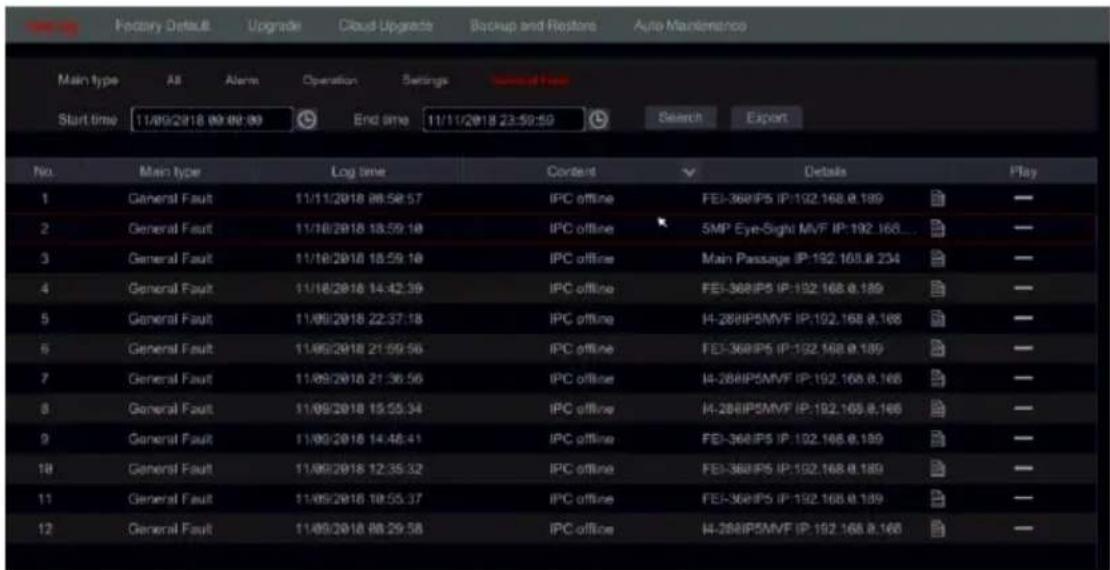
text_image
Main type All Alarm Operation Settings Start time 11/09/2018 00:00:00 End time 11/11/2018 23:50:50 Search Export No. Main type Log time Content Details Play 1 General Fault 11/11/2018 06:58:57 IPC offline FEI-368IP5 IP:192.168.8.189 — 2 General Fault 11/18/2018 18:59:18 IPC offline 5MP Eye-Sight MVF IP:192.168... — 3 General Fault 11/18/2018 18:59:18 IPC offline Main Passage IP:192.168.8.234 — 4 General Fault 11/18/2018 14:42:39 IPC offline FEI-368IP5 IP:192.168.8.189 — 5 General Fault 11/09/2018 22:37:18 IPC offline I4-288IP5MVF IP:192.168.8.166 — 6 General Fault 11/09/2018 21:59:56 IPC offline FEI-368IP5 IP:192.168.8.189 — 7 General Fault 11/09/2018 21:36:56 IPC offline I4-288IP5MVF IP:192.168.8.166 — 8 General Fault 11/09/2018 15:55:34 IPC offline I4-288IP5MVF IP:192.168.8.166 — 9 General Fault 11/09/2018 14:46:41 IPC offline FEI-368IP5 IP:192.168.8.189 — 10 General Fault 11/09/2018 12:35:32 IPC offline FEI-368IP5 IP:192.168.8.189 — 11 General Fault 11/09/2018 18:55:37 IPC offline FEI-368IP5 IP:192.168.8.189 — 12 General Fault 11/09/2018 08:29:58 IPC offline I4-288IP5MVF IP:192.168.8.166Choose the log file from the list and click "Export" button to export the log file.
Click on the “Content” title bar to create filters within the log entries. Click to play a video log if available.
11.3.2 Factory Default
Click Start→Settings→System→Maintenance→Factory Default. Now you have the option to choose between different types of factory default:
1) If you wish to keep the network settings, tick the "Reset all but Network Configuration" marker.
2) “Restore default parameters” will perform a full restore that will keep the device logs intact.
3) “Restore factory settings and clear logs” will perform a full restore and clear the device logs completely.
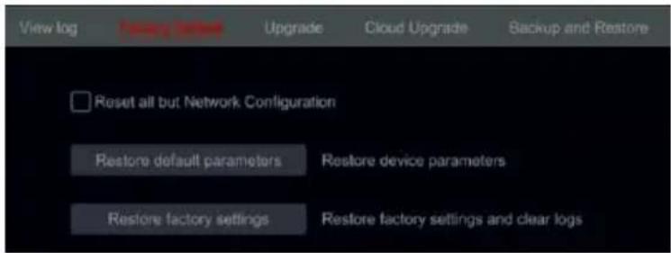
text_image
View log Fixing Settings Upgrade Cloud Upgrade Backup and Restore Reset all but Network Configuration Restore default parameters Restore device parameters Restore factory settings Restore factory settings and clear logs11.3.3 Device Software Upgrade
Before upgrading, download the correct update file from Provision-ISR's website.
Click Start→Settings→System→Information→Upgrade.
The upgrade steps are as follows:
① Copy the upgrade software into the USB storage device.
② Insert the USB storage device into the USB slot of the device.
③ Select the USB device under the “Device Name” option and go to the path where the upgrade software exists. Select the upgrade software and click “Upgrade”. The system will automatically restart during the upgrade process. Do not power off the device during upgrading.
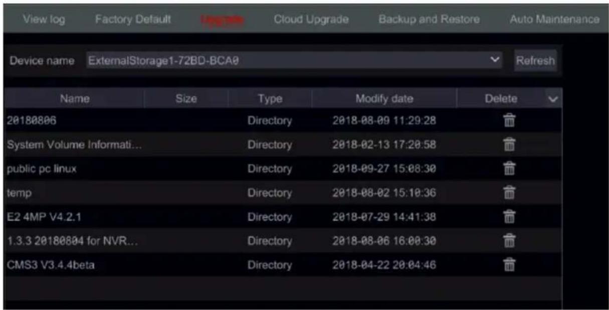
text_image
View log Factory Default Cloud Upgrade Backup and Restore Auto Maintenance Device name ExternalStorage1-72BD-BCA0 Refresh Name Size Type Modify date Delete 20180806 Directory 2018-08-09 11:29:28 System Volume Informati... Directory 2018-02-13 17:20:58 public pc linux Directory 2018-09-27 15:08:30 temp Directory 2018-08-02 15:10:36 E2 4MP V4.2.1 Directory 2018-07-29 14:41:38 1.3.3 20180804 for NVR... Directory 2018-08-06 16:00:30 CMS3 V3.4.4beta Directory 2018-04-22 20:04:46Notes:
1) The file system format of the USB device used for upgrading, backing up and restoring must be FAT32.
2) This method of update will restore all settings to factory default unless stated otherwise.
11.3.4 Cloud Upgrade
Cloud upgrade allows you to update the device directly from Provision-ISR update server. If required, the device will notify you that a new version is available for download and install. The installation of the update will always be done manually.
In order to set the cloud update, click on Start→Settings→System→Information→Cloud Upgrade.
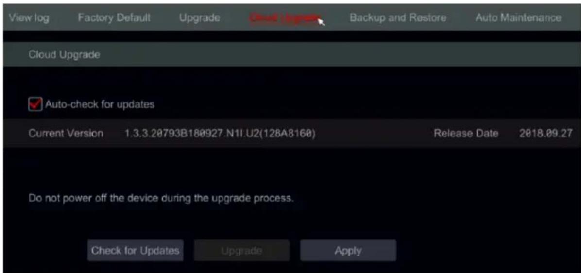
text_image
View log Factory Default Upgrade Cloud Upgrade Backup and Restore Auto Maintenance Cloud Upgrade ✓ Auto-check for updates Current Version 1.3.3.20793B180927.N11.U2(128A8160) Release Date 2018.09.27 Do not power off the device during the upgrade process. Check for Updates Upgrade ApplyTick the “Auto-Check for updates” for the device to perform routine checks for new FW on a weekly basis.
This interface will show the current version and its release date. Click on “Check for Updates” in order to check for updates manually. If a new update has been found, click on “Upgrade” to commence the download the update process. The process will take \~5-12 minutes. The device will reboot several times throughout it.
Notes:
1) Cloud update requires an active connection to the internet. Download time depends on your connection.
2) This method of update will keep all settings as it was before the update.
11.3.5 Backup and Restore
You can back up the configuration file of the device by exporting the file to other storage devices; you can recover the configuration to other device which from the same model as the origin device importing the configuration file to other devices.
Insert the USB storage device into the USB interface of the device and click Start→Settings→System→Maintenance→Backup and Restore.
- Backup
Select the USB device under “Device Name”, then go to the path where you want to store the configuration backup file and click “Backup”. Click “OK” to confirm.
Note: If you wish to backup network settings as well, make sure to tick the relevant box.

text_image
Backup include Network Configuration New folder Backup Recover- Recover
Select the USB device under “Device Name” option. Find the configuration backup file and click “Recover”. Click “OK” to confirm.
11.3.6 Auto Maintenance:
You can set an interval of days/times for auto maintenance. This will reboot the device at the configured time to ensure that the memory, buffers and cache memory are always cleared.
Click Start→Settings→System→Auto Maintenance. Tick "Enable", set the days interval and the point of time during that day. It is highly advisable to choose a time where there is less chance for an incident to occur. During the auto maintenance procedure the device will reboot so recording will not be available.
Click "Apply" – the next reboot date and time will appear in the interface.
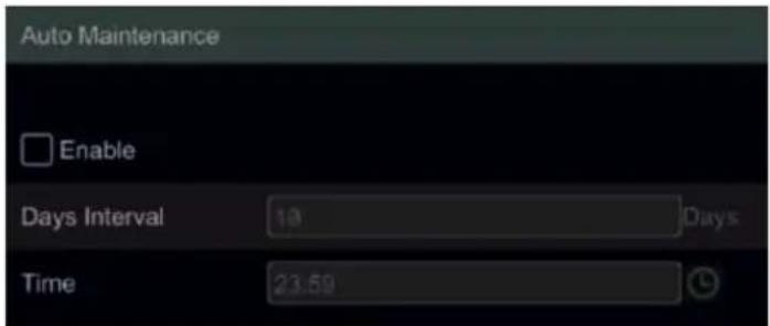
text_image
Auto Maintenance Enable Days Interval 10 Days Time 23.5911.3.7 View Log
Click Start→Settings→System→ View Log. Select the log type, click 📊 to set start time and end time and click “Search” button. The searched log files will be displayed as a list.
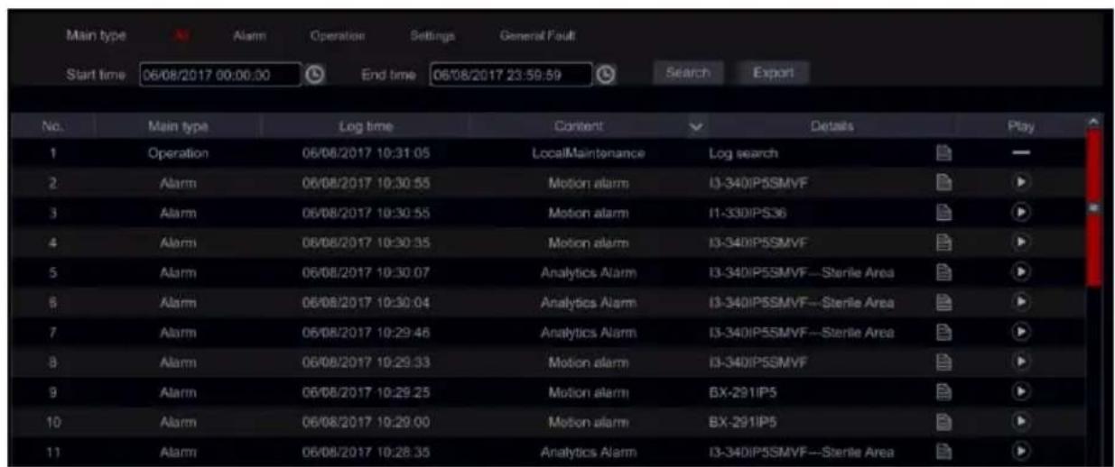
text_image
Main type Start time 06/08/2017 00:00:00 End time 06/08/2017 23:59:59 Search Export No. Main type Log time Content Details Play 1 Operation 06/08/2017 10:31:05 LocalMaintenance Log search 2 Alarm 06/08/2017 10:30:55 Motion alarm I3-340IPSSMVF 3 Alarm 06/08/2017 10:30:55 Motion alarm I1-330IPS36 4 Alarm 06/08/2017 10:30:35 Motion alarm I3-340IPSSMVF 5 Alarm 06/08/2017 10:30:07 Analytics Alarm I3-340IPSSMVF—Sterile Area 6 Alarm 06/08/2017 10:30:04 Analytics Alarm I3-340IPSSMVF—Sterile Area 7 Alarm 06/08/2017 10:29:46 Analytics Alarm I3-340IPSSMVF—Sterile Area 8 Alarm 06/08/2017 10:29:33 Motion alarm I3-340IPSSMVF 9 Alarm 06/08/2017 10:29:25 Motion alarm BX-291IP5 10 Alarm 06/08/2017 10:29:00 Motion alarm BX-291IP5 11 Alarm 06/08/2017 10:28:35 Analytics Alarm I3-340IPSSMVF—Sterile AreaChoose the log file from the list and click "Export" button to export the log file.
Click ▼ on the “Content” title bar to create filters within the log entries. Click ▶ to play a video log if available.
11.3.8 View System Information
Click Start→Settings→System→Information and choose the corresponding menu to view the "Basic", "Camera Status", "Alarm Status", "Record Status", "Network Status" and "Disk" information.
12 Remote Surveillance
12.1 Mobile Client Surveillance
① If you are intending to use Provision-ISR cloud service, make sure to enable NAT in the device. Refer to 11.1.6 NAT Configuration for details.
② Download and install the mobile app "Provision Cam2" (Available for iOS & Android).
③ Run the mobile app, go to the “Add Device” interface and click ☐ to scan the QR Code from the device (Go to Start→Settings→System→Information→Basic to view the QR Code of the device).
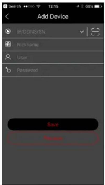
text_image
Search •••••• 12:15 69% Add Device IP/DDNS/SN Nickname User Password Save Name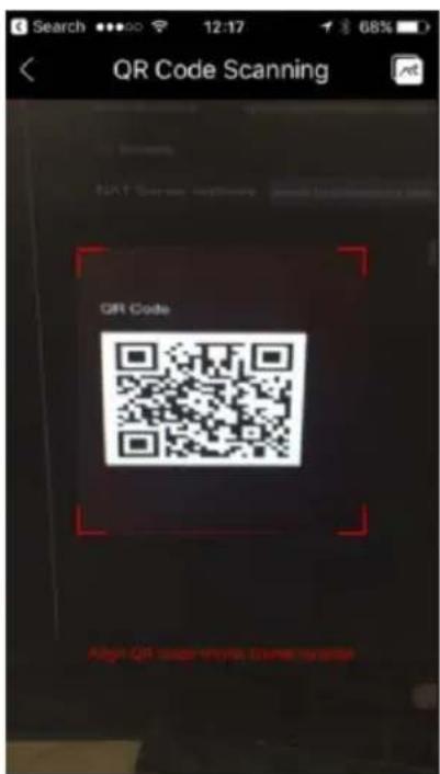
text_image
QR Code Scanning QR Code Align QR code-name code version④ After scanning the OR Code successfully, input the login credentials to log into the device.
⑤ You can also use the app for LAN/WAN connection as described below.
12.2 Web LAN Access
① Click Start→Settings→Network→TCP / IP to go to the “TCP / IP” interface. Set the IP address, subnet mask, gateway, preferred DNS and alternate DNS.
② Open your preferred internet browser (Must Support NPAPI plug-ins) and input the IP address of the device in the browser address bar. You can change the display language on the top right corner of the login interface. Input the username and password of the device in the interface and click “Login” to go to the live preview interface.
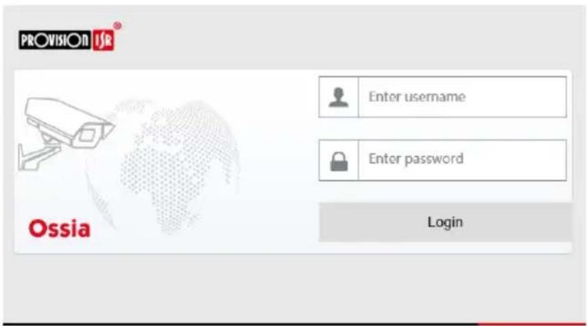
text_image
PROVISION ISR Enter username Enter password Login OssiaNotes: 1. Please make sure that the IP address of both the device and the computer are in the same local network segment. For example, supposing that the IP address of the computer is 192.168.1.YYY, the IP address of the device shall be set to 192.168.1.XXX. 2. If the HTTP port of the device is different than 80, you need to input the IP address plus the port number in the browser's address bar when accessing the device over network. For example, the HTTP port is 81. You should enter http://192.168.1.42:81 in the IE address bar.
12.3 Web WAN Access
NAT Access
① Set the network of the device. Please refer to 11.1.1 TCP/IP Configuration for details.
② Enable NAT. Please refer to 11.1.6 NAT Configuration for details.
③ Open your preferred internet browser (The browser must support NPAPI plugins) and input the NAT server address www.provisionisr-cloud.com in the address bar and press enter. If it is the first time you connect via P2P then download the plugin, close your browser and install it on your system.

text_image
PROVISION ISRA English Enter device serial number Enter username Enter password Login OssiaInput the serial number (click on the tool bar at the bottom of the live preview interface to see the serial number of the device), user name (the user name of the device, admin by default) and password (the password of the device, 123456 by default), select the display language on the top right corner of the interface and click “Login” button to go to the web client interface.
▶ PPPoE Access
① Click Start→Settings→Network→TCP/IPv4. Check “Enable” in the “PPPoE settings” and input the username and password you get from your ISP. Click “Apply” to save the settings.
② Click Start→Settings→Network→Network Status to view the IP address of the device.
③ Open IE browser on a computer, input the IP address of the device in the web browser address bar and press enter. Input the username and password of the device and click “Login” to go to the device’s web interface.
Router Access
① Click Start→Settings→Network→TCP/IPv4. Set the IP address, subnet mask, gateway, preferred DNS and alternate DNS of the device.
② Set the HTTP port (it is advised to modify the HTTP port since the default HTTP port 80 might be occupied) and enable UPnP function in both the device and the router. If the UPnP function is not available in the router, you need to forward the LAN IP address, HTTP port and server port of the device to the router. Port mapping settings may be different in different routers, so please refer to the user manual of your router for details.
③ Get the WAN IP address of the device from the router. Open internet browser on a computer and input the WAN IP address plus HTTP port like http://116.30.18.215:100 in the browser's address bar. Press enter to go to the login interface. Input the username and password of the device in the interface and click "Login".
Note: If the WAN IP address is dynamic, it is necessary for you to use the domain name to access the device. Click Start →Settings →Network →DDNS to set DDNS (see 11.1.3 DDNS_Configuration_for_details). By using DDNS function you can use the domain name plus HTTP port to gain remote access to the device remotely
12.4 Web-Client
On the first connection via any of the supported web-browsers, you will have to install the web client. Upon connection, you will be prompt to install the web-client.
The plugin is not installed, please click to download and install. Before installation, please close your browser.
1) Click on the marked area to download the installation file.
2) It is highly advisable to close all of the open internet browsers and tabs before running the installation file.
3) Run the installation file and open the web browser again
4) If pormpted, allow the internet browser to activate the plug in.
12.5 Web Remote Control
In order to work properly, web-browsers for Windows OS must support NPAPI plug-ins. For MAC OS – Safari browser is supported.
When you access the device through web browser for the first time, you will need to download and install the web-client components. The buttons and icons on the top right corner of the remote interface are introduced as follows.
admin: the logged user name.
Logout: click to log out of the system and return to the login interface.
Modify Password: click to change the password of the current user. Input the current password and set a new password in the popup window. Click “OK” button to save the new password.
Local Settings: click to change the local settings. Set the snapshot number, path and record path as shown below. Click “Apply” button to save the settings.
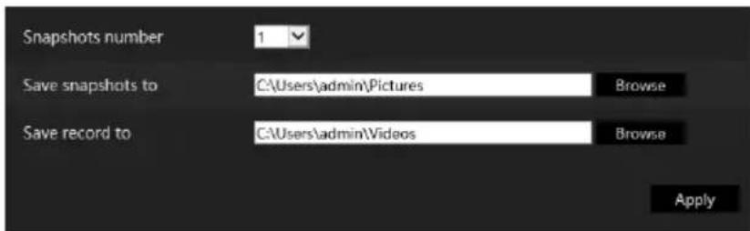
text_image
Snapshots number 1 Save snapshots to C:\Users\admin\Pictures Browse Save record to C:\Users\admin\Videos Browse Apply12.5.1 Remote Live-View
Click “Live Display” in the remote interface. The live-view interface is divided to four areas as marked in the following picture.
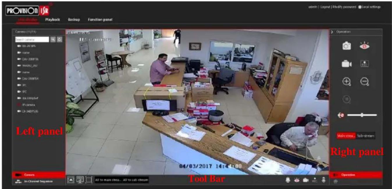
text_image
PROVISION ISR File Browser Playback Backup Function panel admin | Logout | Modify password | Local settings Camera (11/11) search directory 03.26 18% name DAI-2208756 M4002_282 name DAI-3108754 IPC IPC dHL-3300g54f IP camera DR-3407535 Left panel Operation Main store... Sub-stream Right panel 04/03/2017 14:41:00 Covers In-Channel Sequence Tool BarStart Preview
Select a window in the preview area and click one of the online cameras on the left panel to start live-view of the camera in the selected window. You can click in the general tool bar to fill all the video windows with live video cameras (with the order of cameras appearing on the left side).
▶ Left Panel Introduction
Click < on the left panel to hide the panel and > to show the panel. You can view all the added cameras and groups on the left panel.
- View Camera
Click Camera to view the added cameras. You can view the number of the added cameras and the online cameras. For instance, means that 3 cameras are online out of total of 4 added cameras. You can input the camera name in the search box and click to search the camera. Click to refresh the camera list.
• View Group (Applicable for NVRs only)
Click In-Channel Sequence to view the created groups. The upper area of the left panel displays all the groups and the lower area displays the cameras in the group.
▶ Tool Bar Introduction
| Button | Meaning | |
 | Screen split mode button. | |
 | Click to disable the OSD. Click to enable OSD. | |
 | Full screen mode. When in full screen right click to exit back to normal mode. | |
| All to main strea... All to sub-stream | Select “All Main Stream” or “All Sub Stream” to set the stream of all the cameras together. | |
 | Manual alarm button. Click it to open the selection window. From there manually trigger and clear the alarm-out. | |
 | Fill all windows with live view cameras | |
 | Close all the viewed cameras. | |
 | Start local recording. Click to stop recording. | |
 | Enable audio out to the device. | |
Right Panel Introduction
Click < on the right panel to show the panel and > to hide the panel. The button at the bottom of the panel will open the "PTZ" panel. The Operation button will open the "Operation" panel.
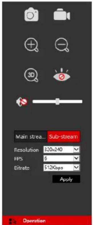
text_image
Main stream... Sub-stream Resolution 320x240 FPS 6 Bitrate 512Kbps Apply Operation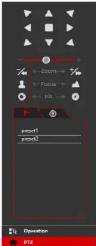
text_image
Zoom Focus Iris preset1 preset2 Operation PTZClick one camera window in the live-view area and click Main Stream to manually set the camera's live-view and local record stream to main stream (For manual record); click Sub-stream to manually set the camera's live-view and local record stream to sub-stream (For manual record). While in sub-stream you can quickly set the resolution, FPS and bitrate and click "Apply" to save the settings.
Operation panel introduction:
| Button | Meaning | |
 | Save local snapshot. | |
 | Start local recording in the viewed resolution; click again to stop recording. | |
 | Digital zoom the image. While zoomed in, left click and drag the mouse on the image to scroll within the image. | |
 | Digital zoom out. | |
 | Close the viewed camera. | |
 | Enable audio. Once enabled, drag the slider bar to adjust the volume. | |
PTZ panel introduction:
| Button | Meaning |
 | Click ▲ / ▶ / ▼ / ▼ / ▶ / ▶ / ▶ / ▶ / ▶ / ▶ to rotate the dome; click to stop rotating the dome. |
 | Drag the slider to adjust the movement speed. |
 | Zoom in/out camera image. |
 | Increase/ decrease the focal length. |
 | Open/Close iris. |
 | View the preset list. Click the call button in the list to call the preset. |
 | View the cruise list. Click the call/stop buttons in the list to start or stop the cruise. |
12.5.2 Remote Playback
Click "Playback" in the remote interface to open the playback interface.
① Choose the record event types and target cameras on the left panel.
② Set the search date/time on the calendar beside the time scale.
③ Click Research for record data.
④ Click Play or directly click on the time scale to play the record.
The working method for the playback time scale is similar to that of the device's local interface.
Please refer to 8.2 Playback Interface Introduction for details.
Introduction of playback control buttons:
| Button | Meaning |
| Stop button. | |
| Rewind button. Click it to play video backward. | |
| Play button. Click it to play video forward. | |
| Pause button. | |
| Deceleration button. Click it to decrease the playing speed. | |
| Acceleration button. Click it to increase the playing speed. | |
| Previous frame button. It works only when the forward playing is paused in single screen mode. | |
| Next frame button. It works only when the forward playing is paused in single screen mode. | |
| Clickto step backward 30s and click+to step forward 30s. | |
| Mark backup start time. Click the time scale and click on it to mark the start time. | |
| Mark backup end time. Click the time scale and click on it to mark the end time. | |
| Commence backup. | |
| View backup tasks status. | |
| Event list button. Click to view the record events in a list. |
12.5.3 Remote Backup
Click "Backup" in the remote interface. You can back up records by event or by time.
By Event
Mark the record type on the left side of the interface. Click to set the start time and end time; mark the desired cameras and click on the right side to search the record (the searched data will be displayed in a list); Mark the record data you wish to backup and click the “Backup” button.
By Time
Click to set the start and end times on the left side of the interface; choose the desired cameras and click on the right side to commence backup.
View Backup Status: Click “Backup Status” to view the current status. Click “Pause” to pause the backup process; click “Resume” to continue; click “Delete” to delete the task.
12.5.4 Remote Configuration
Click “Function Panel” in the remote interface and configure the camera, record, alarm, disk, network, account and authority and system of the device remotely. All of these settings are identical to the device local interface. See the configuration chapters of the device local interface for details.
Appendix A: FAQ
Q1. Why can't I find the HDD?
a. Please confirm that the power and SATA cables are connected firmly to the HDD.
b. Make sure that you use the power adaptor supplied with the device.
c. Make sure the HDD/s are compatible with the device. See Appendix C: Compatible Device List for details.
d. The HDD might have a technical fault. Try to replace the HDD and try again.
Q2. Why are there is no images output for some or all of the camera windows?
a. If you have problems with IP Cameras:
a) Check that the resolutions and coding of the cameras are supported by the device.
b) Check that the network cables of the IP camera and device are both connected properly.
c) Check that the network parameters of the device and camera are set correctly and that both the device and the cameras are on the same network segment.
d) Try connecting to the IPC directly from a PC to confirm it is working properly.
e) Please make sure the network and the switch both work normally.
b. If you have problems with analog cameras:
a) Check that the camera is powered up and working.
b) Confirm that the device and camera are both working on the same video system (PAL/NTSC)
c) Confirm that the camera's resolution and technology are supported by the device.
d) Confirm that the camera is working using a technician monitor.
Q3. There is no image on the screen after boot-up.
a. Please make sure the screen. HDMI or VGA cables are good and well connected.
b. Try clicking and holding the right mouse button for 6 seconds, then release it.
c. Please make sure the screen supports the minimum resolution of 1280*1024, 1920*1080 or 3840*2160 (4K*2K). Please change a screen to any screen supporting 1280*1024, 1920*1080 or 3840*2160 resolution and reboot the device.
Q4. Forget the password?
a. In case you forgot the password of the administrator admin can be reset through “Security Question” feature.
Click “Edit Security Question” button in the login window and enter the corresponding answer of the selected question in the popup window, the password of admin will be reset to 123456 by default. If you forget the answer of the question or you didn’t configure it, please contact Provision-ISR’s technical support for assistance.
b. The passwords of other users can be reset by the super administrator admin, please refer to 10.1.2 Edit User for details.
Q5. The device refuses to add cameras while it still have available channels?
The device is limited by both number of channels and bandwidth. You can see the bandwidth status on the bottom left of the “add camera” interface. In case you reach the bandwidth limit while you still have available channels – you will need to reduce the bit-rate of the camera before adding it. It is recommended to add cameras by “Quickly Add” for batch adding.
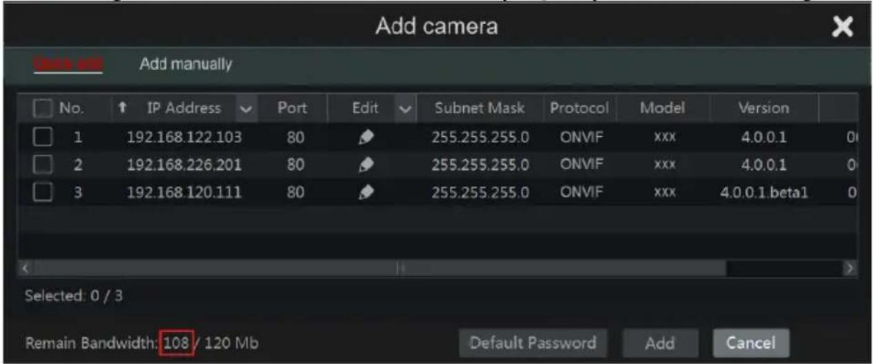
text_image
Add camera Add manually No. IP Address Port Edit Subnet Mask Protocol Model Version 1 192.168.122.103 80 255.255.255.0 ONVIF xxx 4.0.0.1 0 2 192.168.226.201 80 255.255.255.0 ONVIF xxx 4.0.0.1 0 3 192.168.120.111 80 255.255.255.0 ONVIF xxx 4.0.0.1.beta1 0 Selected: 0 / 3 Remain Bandwidth: 108 / 120 Mb Default Password Add CancelQ6. The IP cameras connected to the NVR's PoE port cannot be displayed automatically in the camera list, why?
a. Please check whether the channel assigned to the PoE port is occupied by another IP camera that was added through network.
- Take the 16 CH NVR with 8 PoE ports as an example. The resource distribution of the 16 CH IP cameras is shown in the picture below.
| CH1 | CH2 | CH3 | CH4 | CH5 | CH6 | CH7 | CH8 | CH9 | CH10 | CH11 | CH12 | CH13 | CH14 | CH15 | CH16 |
| POE-1 | POE-2 | POE-3 | POE-4 | POE-5 | POE-6 | POE-7 | POE-8 |
When you add IP cameras through network, the IP cameras will occupy the channels from CH1, CH2, CH3, CH4 and so forth. If you directly connect the IP cameras to the PoE ports of the NVR, the IP cameras will occupy the resource from CH9 to CH16 according to the number of the PoE port each IP camera is connecting to.
Supposing that 12 CH IP cameras have been added to the NVR through network and no IP camera has been directly connected to the PoE port. The 12 CH IP cameras occupy the 8 network resources from CH1 to CH8 and 4 PoE resources from CH9 to CH12 which are supposed to be occupied by connecting the IP cameras directly. In this situation, if you directly connect one IP camera to PoE5, PoE6, PoE7 or PoE8, the IP camera will be displayed in the camera list automatically; if you connect it to PoE1, PoE2, PoE3 or PoE4, it won’t be displayed in the camera list because it is conflicting with the manually added cameras; if you wish to connect it to PoE1, PoE2, PoE3 or PoE4, you should first delete the IP camera which occupies the PoE port resource and reconnect it to the PoE port.
● Take the 8 CH NVR with 8 PoE ports as another example. The resource distribution of the
8 CH IP cameras is shown in the picture below and the adding rules of the IP cameras are similar to the rules mentioned in the above. Please refer to the above for details.
| CH1 | CH2 | CH3 | CH4 | CH5 | CH6 | CH7 | CH8 |
| POE-1 | POE-2 | POE-3 | POE-4 | POE-5 | POE-6 | POE-7 | POE-8 |
b. Please make sure that the internal ethernet port and the IP camera are in the same network segment.
The internal ethernet port and the IP camera which directly connects to the PoE port through ONVIF protocol should be in the same network segment, or you will fail to add the IP camera. Log in the IP camera's web client and enable DHCP (obtain an IP address automatically); or manually change the IP address of the IP camera to make it in the same network segment with the internal ethernet port.
Q7. The IP camera connected to the PoE port of the NVR through ONVIF protocol. It is shown in the camera list, but there is no image output, why?
Please make sure the username and password of the IP camera are correct. The IP camera's username and password can be modified through the two ways mentioned as below.
① Click “Edit Camera” in the Camera module of the setup panel to go to the interface as shown below. Click ☐ modify the username and password of the IP camera (input the correct username and password of the IP camera in the popup window and click “OK” button).
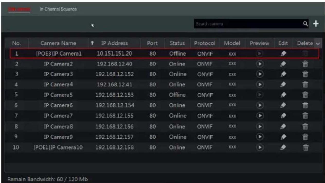
text_image
In-Channel Sequence Search camera No. Camera Name ↑ IP Address Port Status Protocol Model Preview Edit Delete 1 [POE3]IP Camera1 10.151.151.20 80 Offline ONVIF xxx 2 IP Camera2 192.168.12.40 80 Online ONVIF xxx 3 IP Camera3 192.168.12.152 80 Online ONVIF xxx 4 IP Camera4 192.168.12.41 80 Online ONVIF xxx 5 IP Camera5 192.168.12.153 80 Offline ONVIF xxx 6 IP Camera6 192.168.12.154 80 Online ONVIF xxx 7 IP Camera7 192.168.12.155 80 Online ONVIF xxx 8 IP Camera8 192.168.12.156 80 Online ONVIF xxx 9 IP Camera9 192.168.12.157 80 Online ONVIF xxx 10 [POE1]IP Camera10 192.168.12.158 80 Online ONVIF xxx Remain Bandwidth: 60 / 120 Mb② Go to the live preview interface and click in the preview window of the IP camera to edit the IP camera's username and password.
Q8. The system cannot record, why?
a. Make sure the HDD are formatted.
b. Confirm that the record schedule has not been set in manual record mode. Please refer to 7.3.2 Record Schedule Configuration for details.
c. Confirm that the HDD is not full and that “Recycle Record” is enabled. Check the HDD information from Disk Management and if required, please enable the recycle function (please see 7.1.2 Advanced Configuration for details).
d. There is no disk assigned to a group but there are cameras in that group. Please add at least one disk to the group. Refer to 7.5.1 Storage Mode Configuration for details.
e. The HDD might have a technical fault. Try to replace the HDD and try again.
Q9. I fail to access the device remotely through web-browser.
a. Please make sure that you use supported web-browser (browsers supporting NPAPI plug-ins are supported)
b. Please check whether the PC has an enabled firewall or antivirus software. If so, try to disable it and try to access the device again.
c. The Allow & block lists might be active in “Account and Authority” setting. The PC you are using may be in the block list or out of the allow list and cannot access the device remotely.
Q10. ActiveX control cannot be downloaded.
a. IE browser blocks ActiveX controls. Please fix it by following the steps mentioned below.
① Open IE browser. Click →Internet Options.
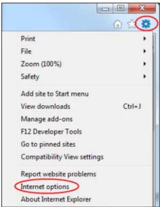
text_image
Print File Zoom (100%) Safety Add site to Start menu View downloads Ctrl+J Manage add-ons F12 Developer Tools Go to pinned sites Compatibility View settings Report website problems Internet options About Internet Explorer② Select Security→Custom Level. Refer to Fig 10-1.
③ Enable all the sub options under “ActiveX controls and plug-ins”. Refer to Fig 10-2.
④ Click "OK" to finish setup.
b. Other plug-ins or anti-virus may block the ActiveX. If the problem persist, please try to disable it.
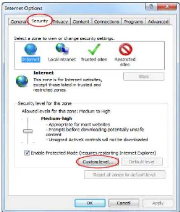
text_image
Internet Options General Security Privacy Content Connections Programs Advanced Select a zone to view or change security settings. Internet Local intranet Trusted sites Restricted sites Internet This zone is for Internet websites, except those listed in trusted and restricted zones. Security level for this zone Allowed levels for this zone: Medium to High Medium-high - Appropriate for most websites - Prompts before downloading potentially unsafe content - Unsigned ActiveX controls will not be downloaded Enable Protected Mode (requires restarting Internet Explorer) Custom level... Default level Reset all zones to default level OK Cancel ApplyFig 10-1
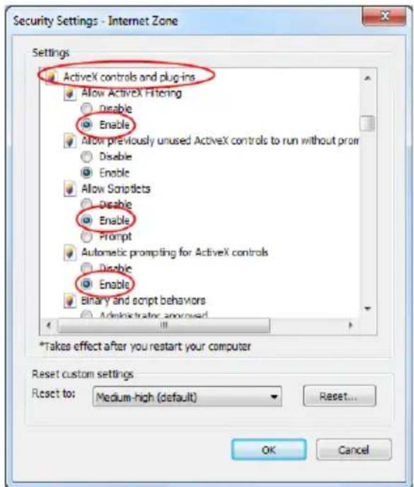
text_image
Security Settings - Internet Zone Settings ActiveX controls and plug-ins Allow ActiveX Filtering Disable Enable Allow previously unused ActiveX controls to run without prom Disable Enable Allow Scriptlets Disable Enable Prompt Automatic prompting for ActiveX controls Disable Enable Binary and script behaviors Administrator approved * *Takes effect after you restart your computer Reset custom settings Reset to: Medium-high (default) Reset... OK CancelFig 10-2
Q11. How to play the backup file?
a. If you made the backup by AVI format – it can be played in all common media players.
- If you made the backup by private format, the device will create a RPAS package along with the backup data. Extract the “RPAS.zip” and click “RPAS.exe” to set up RPAS. After the setup is completed, open the RPAS player and click “Open Folder” button to select the record data. Refer to Fig 11-1.
Select camera in the resource tree on the left side of the interface to play the camera record.
Click 📄 on the tool bar under the camera image to enable audio. Refer to Fig 11-2.
Note: The record will not have audio output if you disable the audio when recording on the device. Please see 7.1.1 Mode Configuration and 7.2 Encode Parameters Setting for details.
b. Record backed up through can only be backed up using AVI format.
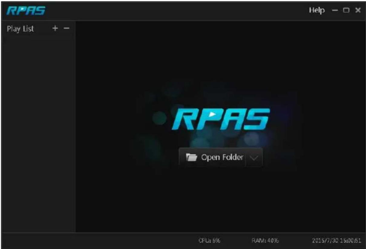
text_image
RPAS Play List + - RPAS Open Folder CPU: 5% RAM: 40% 2015/7/30 15:00:51Fig 11-1
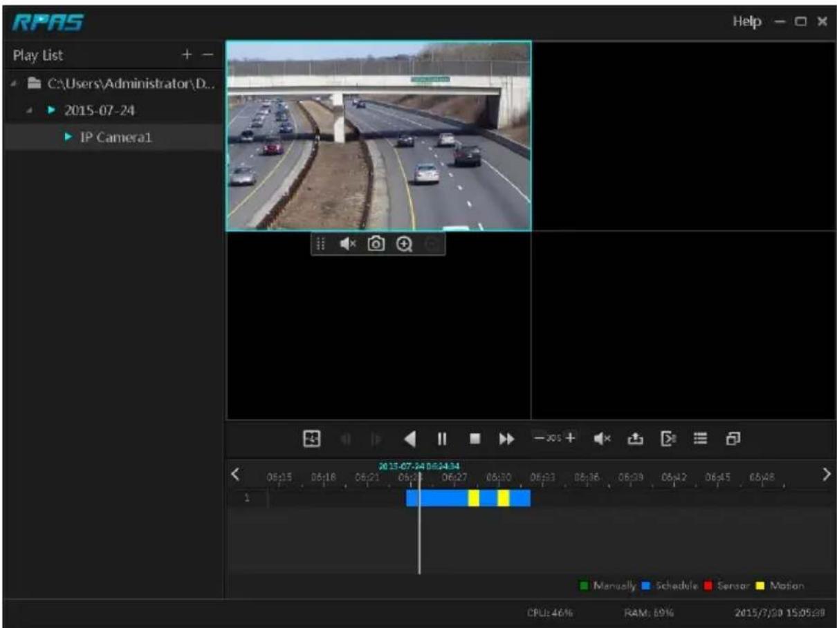
text_image
RPAS Play List C:\Users\Administrator\D... 2015-07-24 IP Camera1 Help 2015-07-24 06:24:34 06:15 06:16 06:21 06:24 06:27 06:30 06:33 06:36 06:39 06:42 06:45 06:48 Manually Schedule Sensor Motion CPU: 46% RAM: 69% 2015/7/20 15:05:30Fig 11-2
Appendix B: Calculate Recording Capacity
The recording capacity is mainly up to the record resolution, record stream and bitrate. Different image quality parameters will take different disk capacities in equal times. The bigger the record resolution, record stream and record bitrate is, the more disk capacity is taken up in equal times. The calculation format of recording capacity is shown as below.
Recording Capacity(MB) = Bitrate(Kbps) ÷ 1024 ÷ 8 × 3600 × Recording hours per day × Record Storage Days × channel numbers
3600 means record for an hour (1TB=1024GB, 1GB=1024MB, 1MB=1024KB, 1Byte=8bit).
| Record Bitrate (Kbps) | Used Space (MB/Hour) | Used Space (MB/Day) |
| 10240 | 4500 | 108000 |
| 8192 | 3600 | 86400 |
| 6144 | 2700 | 64800 |
| 4096 | 1800 | 43200 |
| 3072 | 1350 | 32400 |
| 2048 | 900 | 21600 |
| 1024 | 450 | 10800 |
| 768 | 337.5 | 8100 |
| 512 | 225 | 5400 |
| 384 | 168.75 | 4050 |
| 256 | 112.5 | 2700 |
The table below shows the recording capacity requirements for record storage of 30 days.
| Record Bitrate (Kbps) | Recording Capacity(TB) | |||||
| 1CH | 4CH | 8CH | 16CH | 32CH | 64CH | |
| 10240 | 3.09 | 12.36 | 24.72 | 49.44 | 98.88 | 197.76 |
| 8192 | 2.48 | 9.89 | 19.78 | 39.56 | 79.11 | 158.21 |
| 6144 | 1.86 | 7.42 | 14.84 | 29.67 | 59.33 | 118.66 |
| 4096 | 1.24 | 4.95 | 9.89 | 19.78 | 39.56 | 79.11 |
| 3072 | 0.93 | 3.71 | 7.42 | 14.84 | 29.67 | 59.33 |
| 2048 | 0.62 | 2.48 | 4.95 | 9.89 | 19.78 | 39.56 |
| 1024 | 0.31 | 1.24 | 2.48 | 4.95 | 9.89 | 19.78 |
| 768 | 0.24 | 0.93 | 1.86 | 3.71 | 7.42 | 14.84 |
| 512 | 0.16 | 0.62 | 1.24 | 2.48 | 4.95 | 9.89 |
| 384 | 0.12 | 0.47 | 0.93 | 1.86 | 3.71 | 7.42 |
| 256 | 0.08 | 0.31 | 0.62 | 1.24 | 2.48 | 4.95 |
For instance, there is a 32CH device recording 24 hours per day and the record stores for 30 days. The device adopts dual stream recording. The main stream is 4096Kbps and the sub stream is 1024Kbps, then the total recording capacity is 49.45TB (39.56TB + 9.89TB). Considering the format loss of the disk is about 10% , the required disk capacity will be 55TB (49.45TB ÷ (1-10%)).
Appendix C: RAID Types.
RAID0: Splits data evenly across two or more disks, without parity information, redundancy, or fault tolerance.
• Minimum Disks: 2
- Data Striping
- No storage "loss"
- No Redundancy.
RAID1: Mirrors data between 2 disks, creating 50% fault tolerance.
- 2 Disks Exactly
- Data Mirroring
- 50% Storage "Loss" for RAID capability.
• 1 out of the 2 disks can be damaged without loss of information.
RAID 5: 1n of each data packet is stored on the reserved disk (n=number of disks)
• Minimum Disks: 3
• Data Stripping With Parity
• 1 Disk Storage “Loss”.
• 1 Disk Failure Support.
RAID 6: 2n of each data packet is stored on the reserved disk (n=number of disks)
• Minimum Disks: 4
• Data Stripping With Parity
• 2 Disk Storage “Loss”.
• 2 Disk Failure Support.
RAID10: a combination of RAID0 and RAID1 (Data Stripping + Mirroring)
Features:
• Minimum Disks: 4 (Even Number)
• Data Stripping with Mirroring
- 50% Storage Usage.
In case there is a hot swap configured, it will automatically take place of a faulty disk in case of a fault.
For RAID to work properly - All disks must be in the same capacity.
Appendix C: Compatible Device List
Compatible HDD list
| Brand and Series | Capacity | |
| Seagate | Barracuda Series | 500GB /1TB /2TB /3TB |
| SV35 Series (recommended) | 1TB /2TB /3TB | |
| Surveillance HDD Series (recommended) | 1TB /2TB /3TB /4TB /6TB/8TB | |
| Western Digital | Blue Series | 500GB /1TB |
| Green Series | 2TB /3TB /4TB | |
| Purple Series(recommended) | 1TB /2TB /3TB /4TB /6TB / 8TB | |
Compatible USB mobile device
| Brand | Capacity |
| SSK | 2GB |
| Netac | 4GB |
| Kingston | 2GB/8GB/16GB/32GB |
| Aigo | 2GB |
| Smatter vider | 1GB |
| SanDisk | 4GB/8GB/16GB/32GB |