
Countryman GPS Premium - Satellite receiver MEGASAT - Free user manual and instructions
Find the device manual for free Countryman GPS Premium MEGASAT in PDF.


User questions about Countryman GPS Premium MEGASAT
0 question about this device. Answer the ones you know or ask your own.
Ask a new question about this device
Download the instructions for your Satellite receiver in PDF format for free! Find your manual Countryman GPS Premium - MEGASAT and take your electronic device back in hand. On this page are published all the documents necessary for the use of your device. Countryman GPS Premium by MEGASAT.
USER MANUAL Countryman GPS Premium MEGASAT
natural_image
Mechanical component with a 491 mm dimension label, showing black and white parts (no other text or symbols)Countryman GPS Professional
text_image
246 mm 511 mm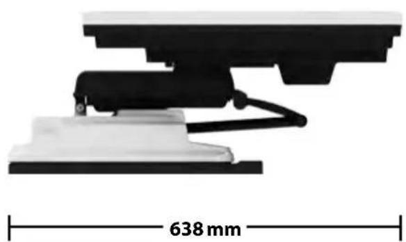
natural_image
Mechanical assembly diagram showing a 638 mm dimension label on a white base (no text or symbols beyond the measurement)5. Technische Daten
Montageabmessungen Countryman GPS Premium
natural_image
Hand pressing down on a surface, no text or symbols visible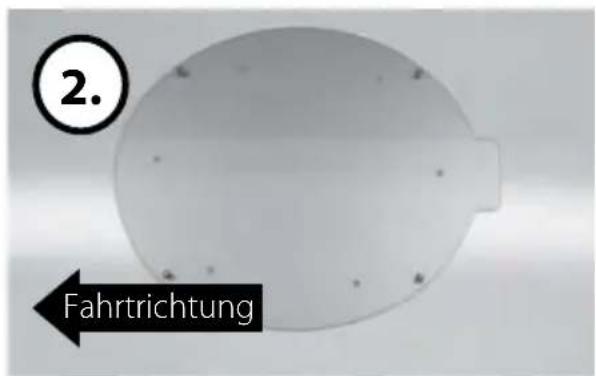
natural_image
Simple circular diagram with a label '3.' in the top-left corner, no text or symbols inside the shape.natural_image
Circular diagram with internal vertical lines and a numbered circle (4.) in the top-left corner, no text or symbols present.natural_image
Hand holding a small object against a plain background, no visible text or symbolsnatural_image
Close-up of a hand holding a tool near a circular metal frame, no visible text or symbolsnatural_image
Close-up of a metallic mirror with a hand holding it, no visible text or symbolsnatural_image
Close-up of a black plastic ring with a small tool inserted, no visible text or symbols6. Montageanleitung
natural_image
Close-up of a curved metallic object with a black border and small holes, labeled with number 9 (no text or symbols on the object itself)natural_image
Close-up of a hand holding a circular object with a black border, marked with number 10 in the corner (no text or symbols on the object itself)natural_image
Close-up of a transparent dome-shaped object with a black outline and circular marker labeled '11.' (no text or symbols on the object itself)natural_image
Circular metallic object with six holes and a small protrusion, labeled '12.' in the top-left corner (no other text or symbols)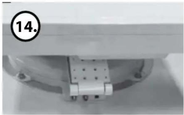
natural_image
Close-up of a mechanical component with a numbered circle marker (14) and no visible text or symbols on the main structure.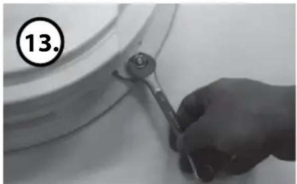
natural_image
Close-up of a hand using a tool to cut or adjust a curved mechanical component, no visible text or symbols.natural_image
Black cable with a connector and small square component, no visible text or symbolsnatural_image
Close-up of a mechanical or electrical connector with wires and connectors, no visible text or symbolsnatural_image
Two white electrical connectors mounted on a wall, one with a U-shaped opening and the other with a rectangular housing (no visible text or symbols)natural_image
Close-up of a mechanical clamp or tool with a metallic component inserted, labeled '18.' in the corner (no other text or symbols visible)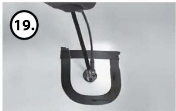
natural_image
Close-up of a hand holding a U-shaped metal object with wires, no visible text or symbolsnatural_image
Close-up of a mechanical component with a black cap and black base, labeled with number 20 (no text or symbols on the object itself)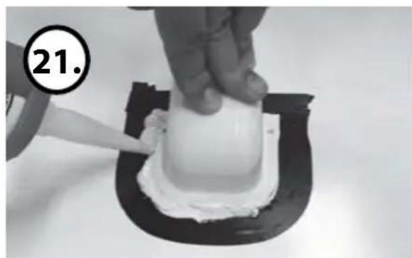
natural_image
Close-up of a hand pressing a white substance onto a black circular object, with number 21 circled in the top-left corner (no text or symbols on the object itself)natural_image
Close-up of a white substance being piped with a tool, placed on a dark surface (no text or symbols visible)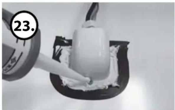
natural_image
Close-up of a piping bag applying white cream onto a black surface, with a numbered label '23.' in the corner (no other text or symbols)natural_image
Close-up of a hand pressing a white cylindrical object into a black mold, with number 24.25 in the corner (no text or symbols on the object itself)natural_image
Close-up of a white plastic electrical plug with a circular inset showing a circle (no text or symbols visible)natural_image
Close-up of a white plastic electrical plug with black wires, lying on a plain surface (no text or symbols visible)natural_image
Coiled black cable with two wires extending outward (no text or symbols visible)natural_image
Close-up of a white industrial air conditioner unit with black cables and a circular dial (no visible text or symbols)natural_image
Close-up of a white industrial control dial with 'HOME' label and electrical socket nearby (no readable text or symbols)Safety information....03
Short description....03
Proper use and operation 03
Delivery....04
Name of parts....05
2. Operating Instruction
Connection Diagram 06
Functional Description 07
Quick Reference 09
3. Program update
Connection Diagram for updating....10
4. Troubleshooting
Troubleshooting 11
5. Specifications
Specifications....12
Dimensions....13
Mounting dimensions....14
6. Mounting instruction....16
1. Introduction
Safety information

Caution – Improper handling by unqualified personnel can cause serious damage to this equipment. Unqualified personnel who tamper with this equipment may be held liable for any resultant damage to the equipment.
Note – Before you begin, carefully read each of the procedures in this manual. If you have not performed similar operations on comparable equipment, do not attempt to perform these procedures.
Short description
These instructions describe the functions and operation of the Countryman GPS auto skew satellite system. Correct and safe operation of the system can only be ensured by following these instructions. Your Countryman GPS is an intelligent satellite TV reception antenna system which can align itself towards a preset satellite automatically as long as the system is located within the footprint of this satellite. The Countryman GPS only occupies requisite space while it performs the necessary adjustments with the slim and agile antenna body. For general operation, please ensure that the system always has a clear view to the sky. If the satellite's signal beam is interrupted by obstacles such as mountains, buildings or trees, the unit will not function and no TV signal will be received The first few pages of these instructions contain information about using the general functions of your Countryman GPS, followed by an explanation of all the adjustment options. The last pages of the instructions cover various technical aspects of the Countryman GPS.
Proper use and operation
This product has been designed for portable use and fixed installation on vehicles with maximum speeds of 130 km/h. It is designed to automatically aim an antenna at geostationary television satellites. The power to the system is supplied by a standard vehicle electrical system with a rated voltage of 12 or 24 Volts DC. For installations where a main connection is provided, a suitable 230 Volt AC to 12 DC Volt power adaptor must be used. Use of the equipment for any other purpose to the one specified is not permitted.
1. Introduction
Delivery
• Countryman GPS Premium/Professional
- Controller incl. bracket
- Car cable
• 12 m coaxial cable for controller (black)
• 12 m coaxial cable for set-top box (grey)
- Mounting plate
- Cable holder
- Cable gland
- Screw set
- User manual
Name of parts
text_image
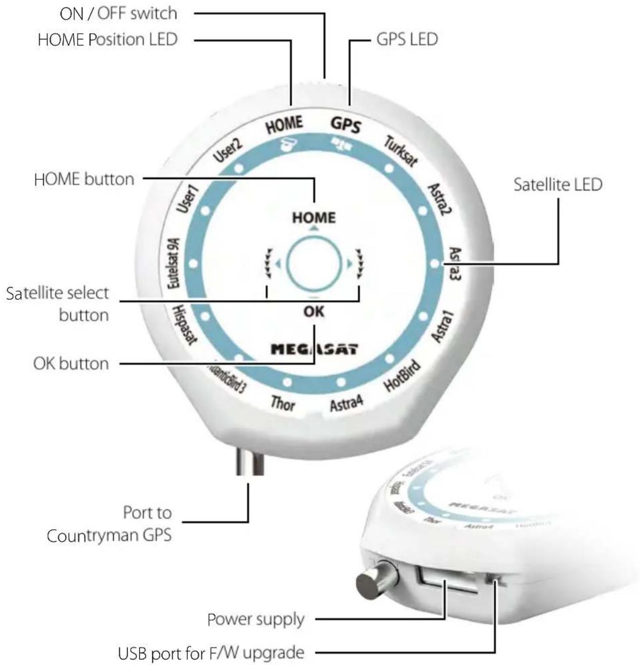
ON / OFF switch HOME Position LED GPS LED HOME button User2 HOME GPS Turksat Astra2 Astra3 Satellite LED User1 Gpset 4 Eurisat Hispsat OK Satellite select button OK button MEGISAT Thor Astra4 HotBird Port to Countryman GPS Power supply USB port for F/W upgrade1. Introduction
Name of parts
text_image
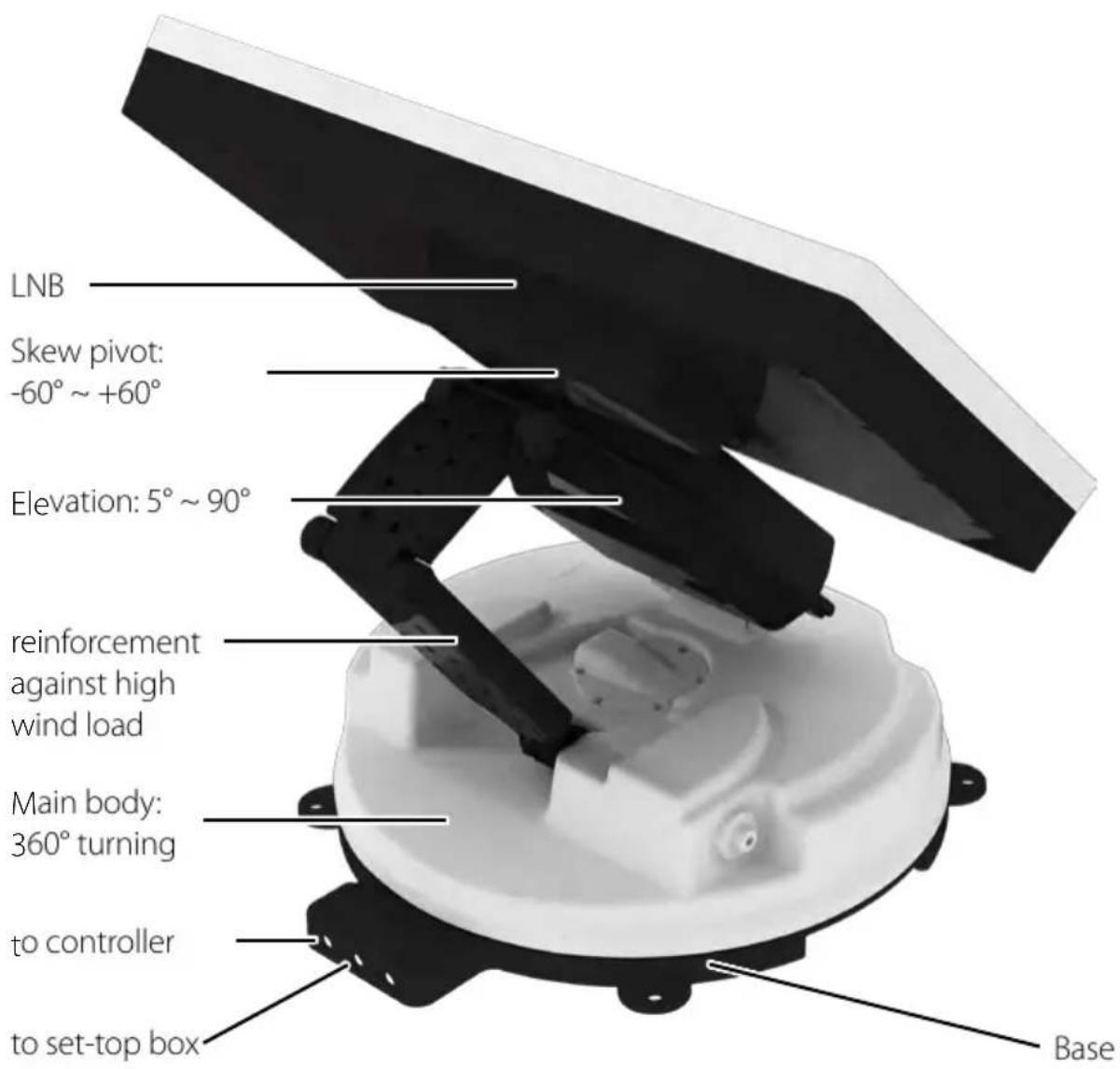
LNB Skew pivot: -60° ~ +60° Elevation: 5° ~ 90° reinforcement against high wind load Main body: 360° turning to controller to set-top box Base2. Operating instruction
Connection Diagram
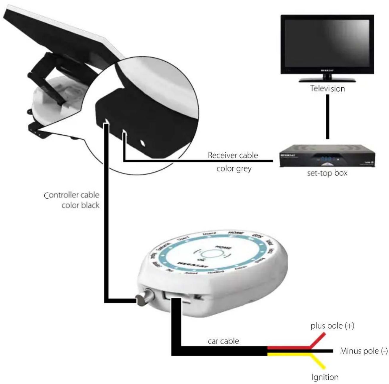
text_image
Controller cable color black Receiver cable color grey car cable plus pole (+) Minus pole (-) Ignition set-top box TelevisionUse the black color 5C Power cable to connect between the controller and antenna. The controller cable looks similar to the antenna receiver cable but you can distinguish them by the color and labeling.
2. Operating instruction
Functional Description
A Power On
| Function Description Operation | ||
ON OFF | "Power" Switch When the all cable connections are completed, switch on with the "Power Switch" button on the top of the controller. | |
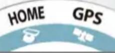 | "Home Status" light Stand By "ON" | If the antenna was at home position, "Home status" light will be solid on to show it is ready to use. |
 | "Home Status" light Flashing↓Turning into "ON" | If the antenna was not in the home position, "Home status" light will flash, and the antenna will return to the home position within a maximum 2 minutes. Then will be solid on. |
The "Home position" means antenna completely folded down to the body part which is the basic position for functioning.
B Selecting the satellite
| Funktion Description Operation | ||
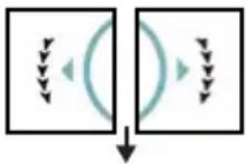  | “Satellite CCW / CW button” Light“OK” button | Once antenna and controller are connected, you can select & change the satellite as you desire. |
| Select the preferring satellite using the “CCW / CW” buttons, then press the “OK” button to accept the setting. | ||
| If you select the wrong satellite, you can re-search target satellite using the “CCW / CW” button, then press the “OK” button to accept the new setting. | ||
C Satellit suchen
| Funktion Description Operation | ||
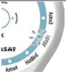 | “Satellite” light | After the satellite selection, “Home Status” light will go off and the LED light of the selected satellite will start flashing. |
| Once selected satellite has been found, the LED light of the satellite will become solid. | ||
2. Operating instruction
D Change satellite
| Funktion Description Operation | ||
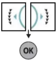 | "Satellite CCW / CW button" Light ↓ "OK" button | if you want to change desired satellite, you can change the target satellite using the "CCW / CW" buttons, then press the "OK" button to select the new satellite. |
E Back to „Home Position“
| Funktion Description Operation | ||
 | “HOME” button | Whenever you wish to return the antenna back to the Home position, press and hold the “Home” button for a few seconds. |
F GPS LED display
| Funktion Description | Operation | |
 | „GPS“ LED | When your Countryman GPS identifies a GPS signal, GPS LED light will remain on, regardless if the antenna is pausing or moving. GPS can help to search for the satellite faster & catch the optimum satellite signal, and assist Countryman GPS Premium to achieve the best elevation & skew angle. |
| Also, while program updating, the GPS LED light will flash to show the update procedure is processing. During this time, GPS LED light on doesn’t mean the unit is communicating with GPS satellite. |

Warning!
When starting the motor, the antenna will automatically moves to the park position. To ensure this please don't turn off the controller!
2. Operating instruction
Quick Start
| Description | |
| Settings & Connecting | 1. Take out the antenna from carrying case, and place it on the flat ground (or mount it on the top of the camper) facing South & no obstacle.2. Connect the left port of the antenna, which located at the rear of the main unit, to the controller using controller cable.a) One end of the controller cable connect to „controller“ port of the main unit of the antenna.b) The other end of the controller cable connect to the port of the controller.3. Connect the power cable to controller.a) If you use the power source from a car or caravan etc, use the cigarette lighter adaptor to connect the power to controller.b) Otherwise use a suitable 12 Volt DC adaptor to connect the power to controlle.4. Connect between the right port of the antenna, which located at the rear of the main unit, to the receiver using receiver cable.. |
| Operation (Search satellites) | 1. Switch on with the “Power switch” button on the top of the controller.2. Upon power on, all LED will flash twice.3. Wait until “HOME Status” light & one “Satellite LED” light, which you set previously or the first satellite in the controller (Turksat), remain solid on.4. Select the desired satellite using the “CCW / CW” buttons, then press the “OK” button to select.5. IF the satellite LED light starts flashing, please wait for a while until it turns to keep the LED on steadily.6. When the satellite LED light stays on, the selceted satellite has been located and a signal can be seen on the satellite TV. |

When you move the car, the flat dish of the antenna must be at the Home position.
3. Program update
Connection diagram
text_image
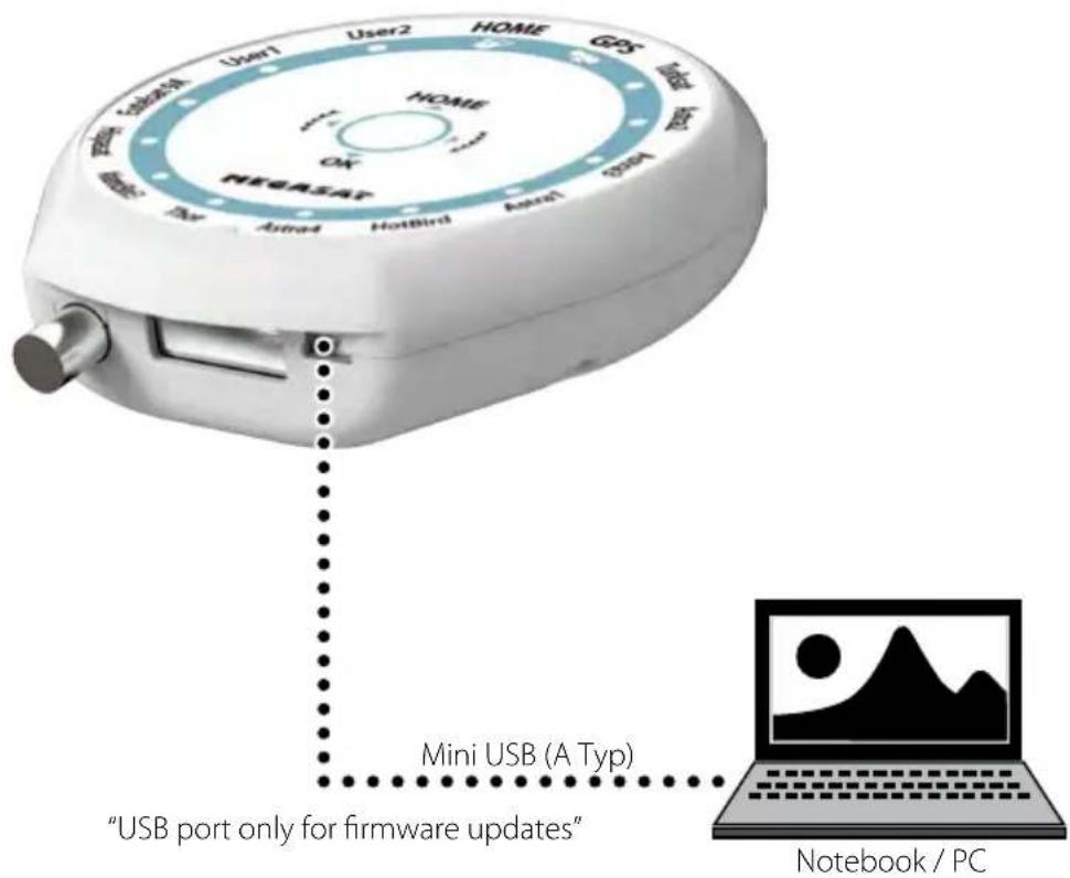
MEGASAT User1 User2 HOME GDS USB USB Astra4 Hotbird Astra1 DSS Mini USB (A Typ) "USB port only for firmware updates" Notebook / PCSimply connect the Controller to PC using USB cable. USB cable is not included in the package.
Note:
For frimware and satellite updates, please visit our homepage: www.megasat.tv
4. Troubleshooting
There are a number of common issues that can affect the signal reception quality or the operation of the Countryman GPS. The following sections address these issues and potential solutions.
A. No function when you power on the Controller
-
Check again all the cable connections have been made correctly..
-
Connection between the power and controller
-
Connection between the controller and the antenna. Make sure that the left port of the antenna should be connected to the controller.
-
Check if the cigarette lighter adaptor or adaptor has been damaged.
B. Fail to search the selected satellite
- Satellite signals can be blocked or degraded by buildings, trees. Make sure there are no obstructions in a southward direction.
- Check your program of Controller often, and get the latest updates.
C. Mechanical problems
- If the antenna does not move into desired position.
- Try to power OFF/ON again.
- If the antenna makes a noise whilst remaining static.
- Try to power OFF/ON again. If problem persists, please contact your local distributor for assistance.
D. Other issues
- If the system has been improperly wired, it will not operate properly. Contact your local distributor for assistance of cable damage.
5. Specifications
Specifications
| Product Countryman GPS Premium Countryman GPS Professional | ||
| Weight 13,5 kg 16,5 kg | ||
| Work Condition Stationary Stationary | ||
| Antenna Gain 33.7 dBi @ 12.7GHz 36.1 dBi @ 12.7GHz | ||
| Min EIRP 50 dBW 47 dBW | ||
| Polarization Linear (Horizontal / Vertical) Linear (Horizontal / Vertical) | ||
| LNB Output | 1 output | 1 output |
| LNB Input Frequency | 10.7 ~ 12.75 GHz | 10.7 ~ 12.75 GHz |
| LNB Output Frequency | 950 ~ 2,150 MHz | 950 ~ 2,150 MHz |
| Angle Range | 5° ~ 90° / 360° / -60° ~ +60° | 55° ~ 90° / 360° / -60° ~ +60° |
| Satellite Searching Time | ca. 1-2 min. | ca. 1-2 min. |
| Power Requirement | DC 12~24V | DC 12~24V |
| Power Consumption | max. 75 W (in searching) max. 75 Watt (in searching) | |
| Operating Temperature | -20°C ~ +60°C | -20°C ~ +60°C |
Declaration of Conformity
Note:
Weight and dimensions are not absolutely exact values.
Technical details can be changed at any time (according to manufacturer) without prior notice.
Declaration of Conformity
This complies with the following directives / standards is confirmed:
Electromagnetic Compatibility Directive 2004/108/EC
EN 55013: 2001 + A1: 2003 + A2: 2006
EN 55020: 2007
EN 61000-3-2:2006 + A1:2009 + A2:2009
EN 61000-3-3:2008
Low Voltage Directive 2006/95/EG
EN 60065: 2002 + A1: 2006 + A11: 2008
5. Specifications
Dimensions
Countryman GPS Premium
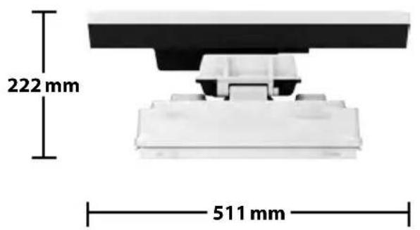
text_image
222 mm 511 mm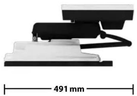
natural_image
Mechanical component with a 491 mm dimension label, showing black and white parts (no other text or symbols)Countryman GPS Professional
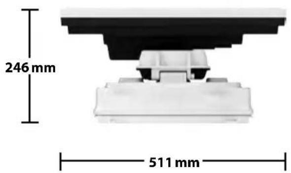
text_image
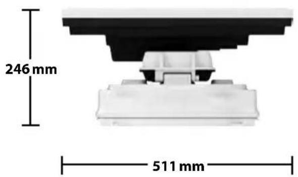
246 mm 511 mm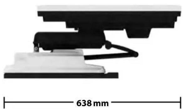
natural_image
Mechanical assembly diagram showing a 638 mm dimension label on a white base (no text or symbols beyond the measurement)5. Specifications
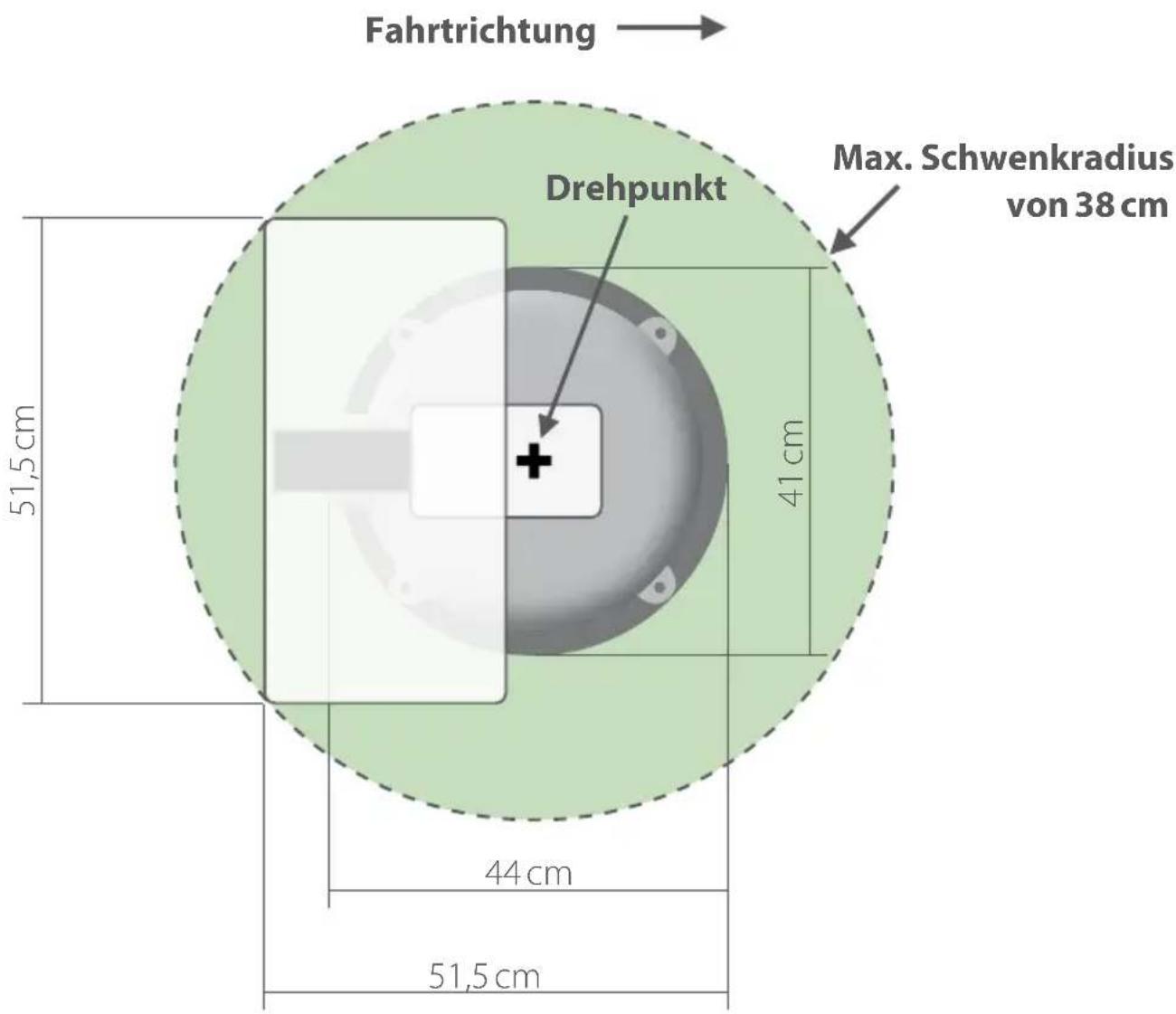
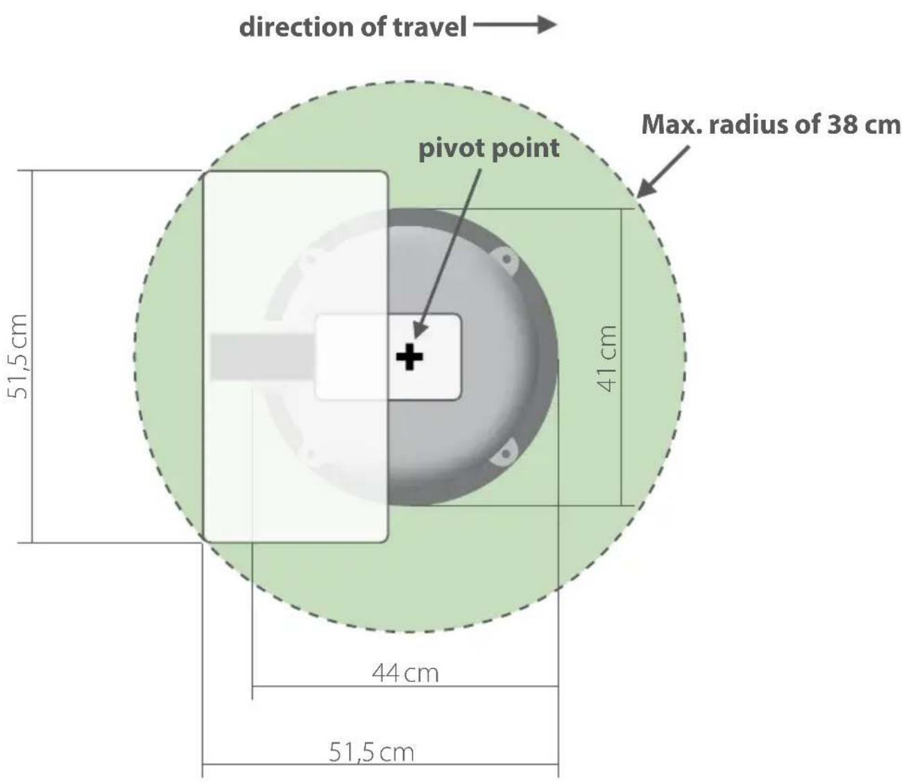
Mounting Dimensions Countryman GPS Premium
text_image
direction of travel pivot point Max. radius of 38 cm 51,5 cm 41 cm 44 cm 51,5 cm5. Specifications
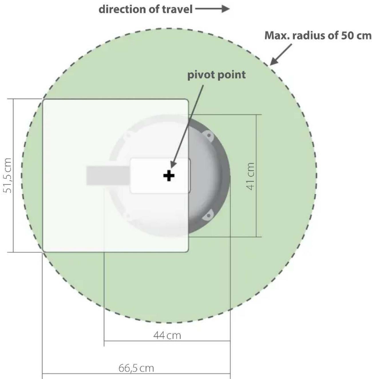
Mounting Dimensions Countryman GPS Professional
text_image
direction of travel Max. radius of 50 cm pivot point 51,5 cm 41 cm 44 cm 66,5 cm6. Mounting instruction
natural_image
Hand pressing down on a surface, no text or symbols visible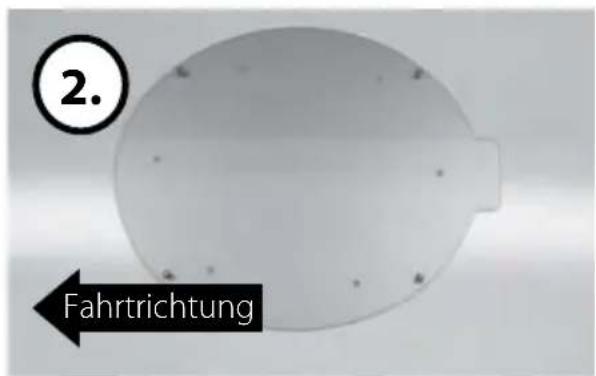
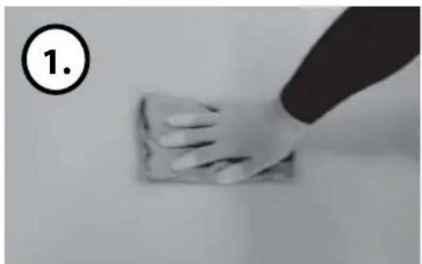
Clean the surface with cleaner. Locate mounting plate in the center of car roof.
natural_image
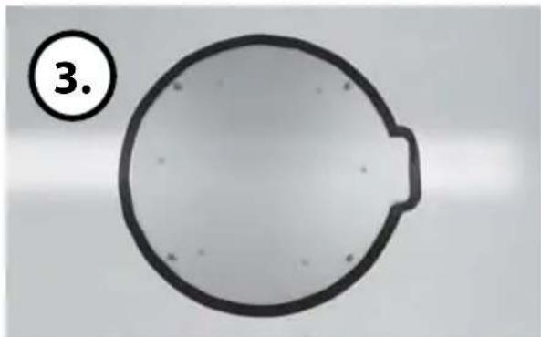
Simple circular diagram with a label '3.' in the top-left corner, no text or symbols inside the shape.Attach friction tape outside of the mounting plate by 4mm away from plate edges.
natural_image
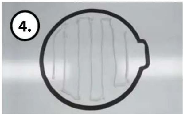
Circular diagram with internal vertical lines and a numbered circle (4.) in the top-left corner, no text or symbols present.Apply silicone within the guided tape line but leave 2cm gap from the line.
natural_image
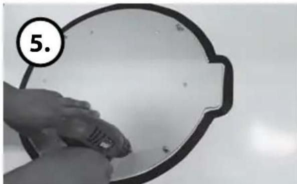
Hand holding a small object against a plain background, no visible text or symbolsPut back the mounting plate on the silicone applied and make 6holes (2mm).
natural_image
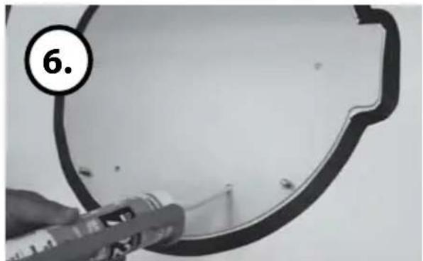
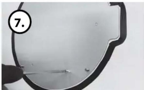
Close-up of a hand holding a tool near a circular metal frame, with no visible text or symbols.Apply silicone on the holes.
natural_image
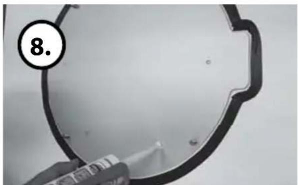
Close-up of a metallic mirror with a hand holding it, no visible text or symbolsAssemble bolts Re-apply silicone to cover bolts assembled
natural_image
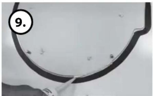
Close-up of a black plastic ring with a tool applying material to its surface, no visible text or symbols6. Mounting instruction
natural_image
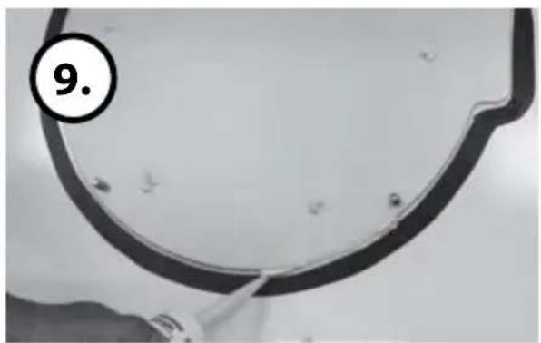
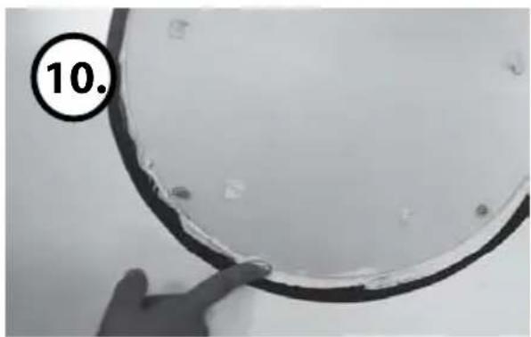
Close-up of a curved metallic object with a black border and small holes, labeled with number 9 (no text or symbols on the object itself)Apply silicone around mounting plate.
natural_image
Close-up of a hand holding a circular object with a black border, marked with number 10 in the corner (no text or symbols on the object itself)Tidy the area silicone applied.

natural_image
Close-up of a transparent dome-shaped object with a black outline and circular marker labeled '11.' (no text or symbols on the object itself)Remove friction tape and get dry. The image you will see. Place main unit on the top of fixed plate.

natural_image
Circular object with small holes and a small protrusion, labeled '12.' in the top-left corner (no other text or symbols)u will see. Place main unit on the top of fixed plate.
natural_image
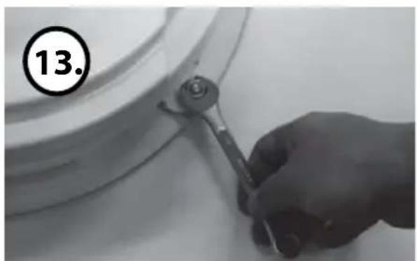
Hand using a wrench to adjust or install a component on a white surface, no visible text or symbolsAttach the antenna to the mounting plate
natural_image
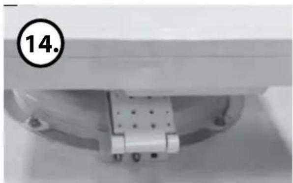
Close-up of a mechanical component with a circular marker labeled '14.' (no readable text or symbols beyond the number)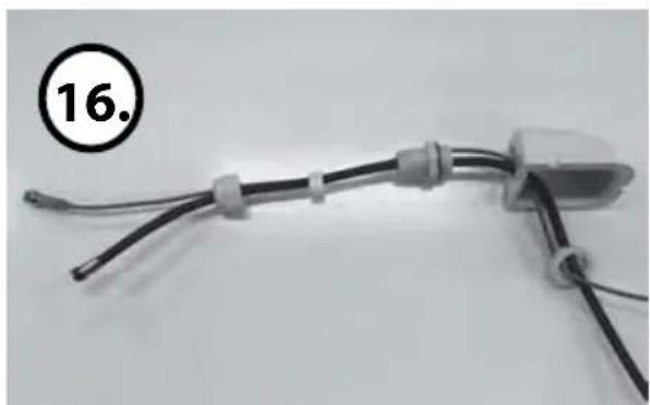
natural_image
Close-up of a black electrical connector with coiled wires and connectors, labeled with number 16 (no text or symbols on the device itself)Insert cables like picture.
natural_image
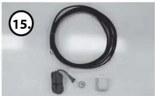
Black cable with attached plug and connector, plus a small square component (no text or symbols visible)Equipment to initiate Cable holder installation
6. Mounting instruction
natural_image
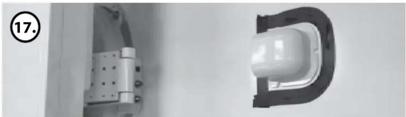
Two white electrical connectors mounted on a wall, one with a U-shaped opening and the other with a rectangular housing (no visible text or symbols)Arrange cable holder in front of (30cm apart from) antenna center by facing open side of cable holder toward projected part of the mounting plate. Then attach friction tape
outside of cable holder
natural_image
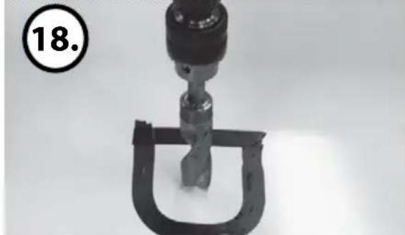
Close-up of a mechanical clamp or spring component with a black housing and a circular label showing number 18 (no text or symbols on the device itself)Make 15mm drill hole in the center of the tape marking.
natural_image
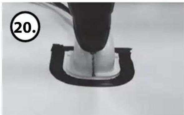
Close-up of a mechanical component with a black cap and black base, labeled with number 20 (no text or symbols on the object itself)lace cable holder in the tape marked and make 3 of 2mm drill holes.
natural_image
Close-up of a white substance being piped with a tool, placed on a dark surface (no text or symbols visible)Fix cable holder on the car roof with 3 of M4x20.
natural_image
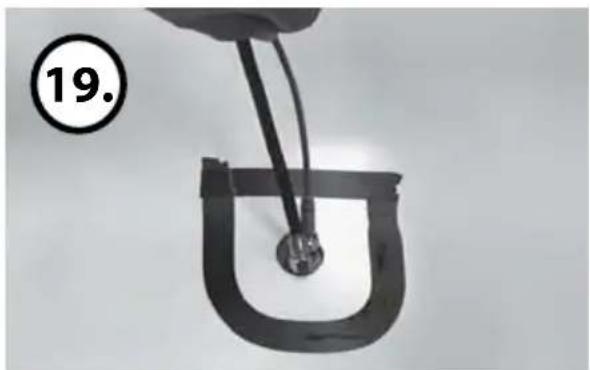
Close-up of a hand holding a U-shaped metal object with wires, no visible text or symbolsInsert Receiver & 5c Power cable through the hole.
natural_image
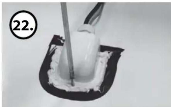
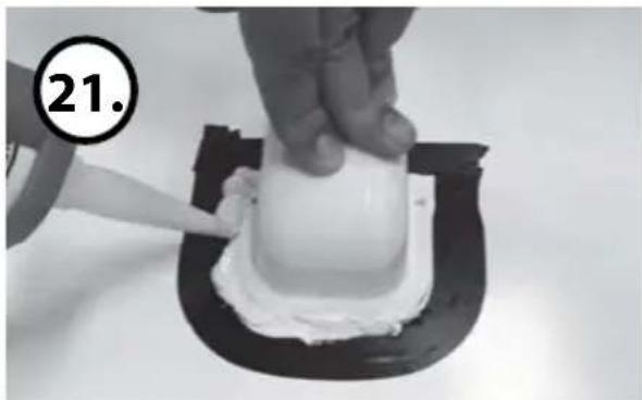
Close-up of a hand applying white cream to a small white object on a black curved surface, with number 21 circled in the top-left corner (no text or symbols on the object itself)Apply silicone around and on the top of screws.
natural_image
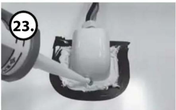
Close-up of a hand applying white cream to a small white object, with a numbered label '23.' in the corner (no other text or symbols)Apply silicone around and on the top of screws.
6. Mounting instruction
text_image
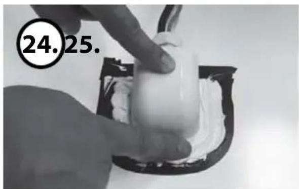
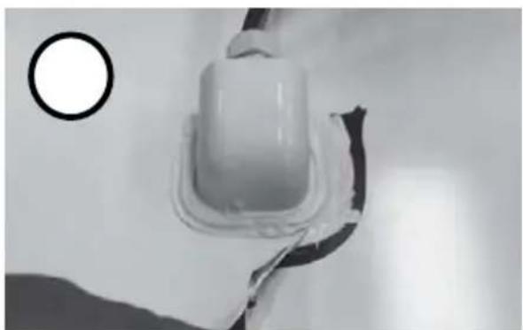
24.25.Tidy silicon.
natural_image
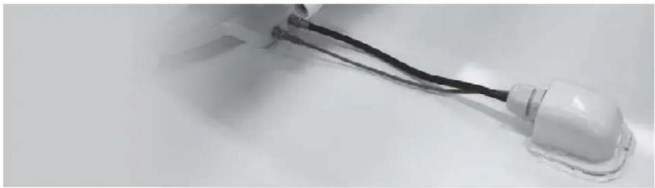
Close-up of a white plastic electrical plug with a circular inset showing a circle (no text or symbols visible)Remove friction tape.
natural_image
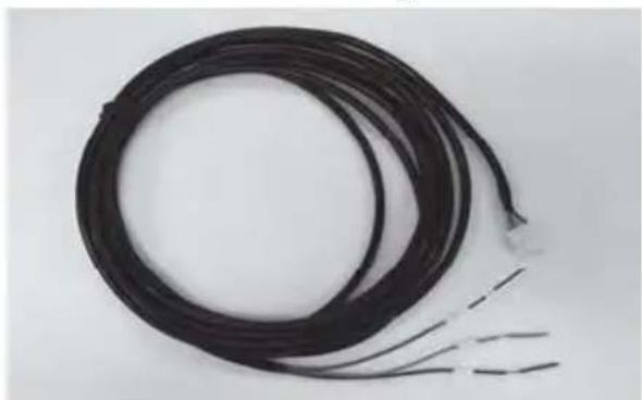
Close-up of a white plastic electrical plug with black wires, lying on a plain surface (no text or symbols visible)Connection battery
natural_image
Coiled black cable with two wires extending outward (no text or symbols visible)Power Input Cable Check Car Battery Polarities (+/-)
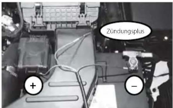
and Ignition Terminal
natural_image
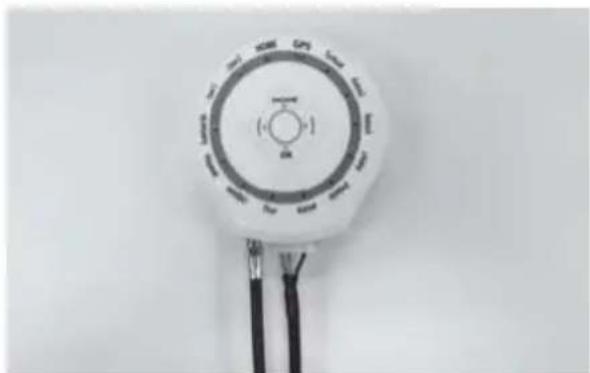
Close-up of a white industrial air conditioner unit with circular dial and black wires (no visible text or symbols)Use Power Input Cable and 5c Power cable to connect to Controller
natural_image
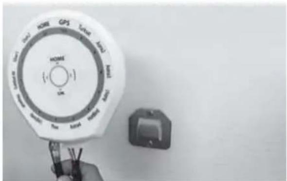
Close-up of a white industrial control dial with GPS and timer, next to a small electrical socket (no visible text or symbols)Place the Controller at where you want
Status: v1.1 August 2014 // Technical changes, misprints and errors reserved.
Megasat Werke GmbH | Industriestraße 4a | D-97618 Niederlauer | www.megasat.tv | info@megasat.tv