K-13474 - Faucet KOHLER - Free user manual and instructions
Find the device manual for free K-13474 KOHLER in PDF.


| Product Type | Bathroom Sink Faucet |
| Brand | Kohler |
| Model | K-13474 |
| Category | Faucet |
| Power Supply | 3V DC (sensor) / 120V AC (power adapter) |
| Mounting Hole Diameter | 32 mm - 38 mm |
| Minimum Distance from Wall | 44 mm |
| Maximum Recommended Temperature | 49°C (adjustable) |
| Main Function | Automatic sensor activation |
| Temperature Limit Adjustment | Yes (with handle or vandal-resistant) |
| Vandal-Resistant Mode | Optional (cap) |
| Material | Chrome-plated brass |
| Number of Mounting Holes | 1 hole |
| Water Supply | Flexible hoses included |
| Filters | Strainers to clean periodically |
| Maintenance | Clean strainers, avoid abrasive products |
| Safety | Follow local codes, disconnect before maintenance |
| Included Parts | Aerator, hex key, filter, power adapter (depending on model) |
| Repairability | Spare parts available (strainers, aerator, sensor) |
Frequently Asked Questions - K-13474 KOHLER
User questions about K-13474 KOHLER
0 question about this device. Answer the ones you know or ask your own.
Ask a new question about this device
Download the instructions for your Faucet in PDF format for free! Find your manual K-13474 - KOHLER and take your electronic device back in hand. On this page are published all the documents necessary for the use of your device. K-13474 by KOHLER.
USER MANUAL K-13474 KOHLER
Bathroom Sink Faucet
K-7514, K-7515, K-7516
K-7517, K-7518, K-7519
K-13460, K-13461, K-13462.
K-13463, K-13466, K-13467.
K-13468, K-13469, K-13472.
K-13473, K-13475, K-13475.
K-45344, K-45345
Mproduct numbers are for Mexico (i.e. K-12345M)
- Observe all local plumbing and building codes.
Shut off the water supply.
This faucet is for use on a single-hole bathroom sink.
For new installations, install the faucet and drain to the sink before installing the sink.
The faucet shown in this guide may differ from your actual product. The installation steps still apply.
In order for this faucet to function properly, install the faucet so the sensor points directly toward the user.
The faucet is rated at 3 V DC 1 W.
Without Escutcheon
1. Faucet Installation
Prepare the Site - AC and Hybrid Models
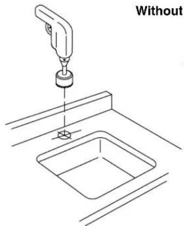
NOTE:Beforedrillingthemountinghole,usethefollowing provisionsforproperplacement:
A 1 - 1 / 4^ (32mm) minimum to 1 - 1 / 2^ (38mm) maximum diameter mounting hole is required.
A minimum distance of 1 - 3 / 4^ (44mm) is required between the back of the spout and the wall to allow access to the screw.
A 1 - 1 / 8^ (29mm) maximum distance is required between the sink bowl edge and the base of the spout.
AAA Battery Operated Models Only
NOTE: When K-13460,K-13461,K-13466orK-13467 are installed to drop-in sinks (sinks with the rim above the deck), the maximum height of the edge of the basin lip is 3/4''(19mm) and the maximum distance from the edge of the sink to the front edge of the faucet is 1/2''(13mm) .
NOTE: When K-13472 or K-13473 are installed to drop-in sinks, the maximum height of the edge of the basin lip is 1 - 1 / 4''(32mm)
NOTE:Beforedrillingthemountinghole,usethefollowing provisionsforproperplacement:
A 1 - 1 / 4^ (32mm) minimum to 1 - 1 / 2^ (38mm) maximum diameter mounting hole is required.
Kohler Co. 3 1244026-2-A
Faucet Installation (cont.)
A minimum distance of 1 - 3 / 4^ (44mm) is required between the back of the spout and the wall to allow access to the screw.
Install the Faucet
Determine the mounting hole location.
- Drill a hole through the mounting surface according to the surface manufacturer's instructions.
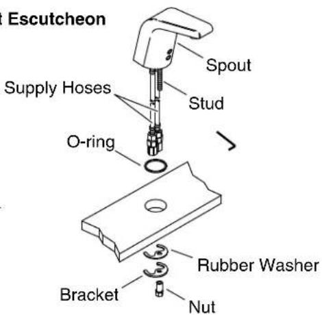
Install the stud to the underside of the faucet.
- Slide the O-ring over the flexible hoses and stud, then seat the O-ring in the groove on the underside of the spout.
- Insert the spout with flexible hoses and stud through the mounting hole.
From under the sink, slide the rubber washer and bracket onto the stud.
- Thread the nut onto the stud to secure the faucet to the mounting surface.
2. Supply Connections
Connect the Filter Assembly
Turn on the water and flush water through the supply stops into a bucket.
Turn off the water.
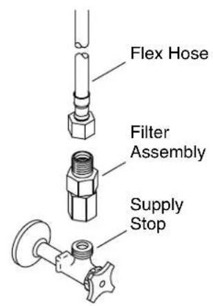
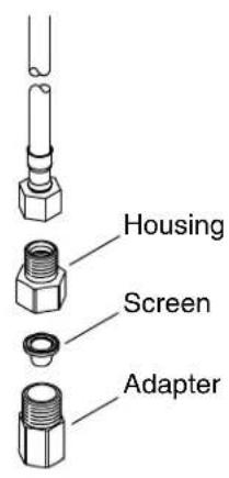
- Remove the filter assemblies from the supply hoses. Then thread a filter assembly onto each supply stop.
Connect the Supplies
For models with twooses, thread the left supply hose to the filter assembly on the hot supply stop and the right supply hose to the filter assembly on the cold supply stop.
For models with onehose,thread the supply hose to the filter assembly on the supply stop.
- Tighten the connections with a small adjustable wrench.
Turn on the water and flush the faucet by activating it.
NOTE:For optimum performance, clean your filter screens periodically. Refer to the Maintenance Guide.
3. Install the Power Supply - Hybrid Models
NOTE: Avoid the area in front of the sensor for 2 minutes after connections are complete. The sensor will not function correctly if it is triggered in the first 2 minutes. Disconnect and reconnect the power to reset the sensor.
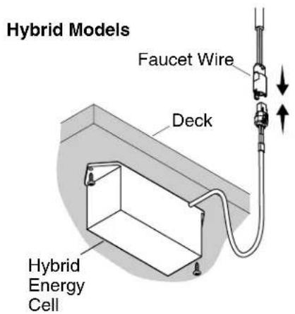
- Mount the Hybrid Energy Cell (HEC) under the counter using two screws (not supplied).
Connect the HEC to the faucet wire. - Avoid the area in front of the sensor for 2 minutes.
4. Install the AC Power Supply
SingleFaucet Installations
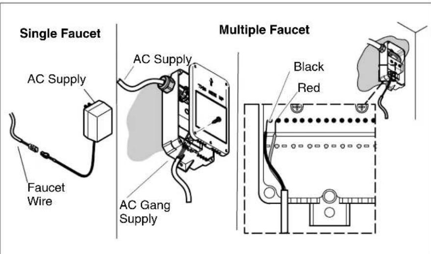
Connect the faucet wire to the AC supply.
Plug the AC supply into the wall outlet.
- Secure any excess wire under the counter.
IMPORTANT! The area in front of the sensor must be free of objects during the 2 minute learning cycle or the faucet may not function properly.
- Allow 2 minutes for the sensor to cycle through the automatic sensing distance.
MultipleFaucet Installations
- Mount the AC supply under the counter using two (not supplied) screws. Orient as shown.
Remove the cover.
Connect the faucet wire to the faucet.
If needed, cut and strip the AC supply wires to length. - Connect the stripped ends to the bottom terminal block (TB2) in the supply box.
Install the AC Power Supply (cont.)
NOTE:If a hard wired installation is required, go to the next installation section.
Plug the AC supply into the wall outlet.
- Secure any excess wire under the counter.
IMPORTANT! The area in front of the sensor must be free of objects during the 2 minute learning cycle or the faucet may not function properly.
- Allow 2 minutes for the sensor to cycle through the automatic sensing distance.
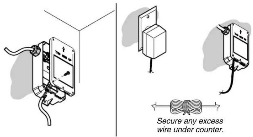
5. Hard Wire Installation - AC Only

WARNING: Risk of Electricalshock. Make sure the power has been disconnected before performing the following procedures.
- Loosen the terminal block screws and remove the wires from the top terminal block.
Loosen the outside nut of the strain relief and remove the power cord. - Put the supply wires through the strain relief and connect to the top terminal block.
NOTE:If a hard wired installation is required, the strain relief may need to be replaced depending on wire used.
Tighten the nut on the strain relief.
Replace the cover, and install and tighten the five screws.
Turn on the AC supply power.
- Secure any extra wire under the counter.
IMPORTANT! The area in front of the sensor must be free of objects during the 2 minute learning cycle or the faucet may not function properly.
- Allow 2 minutes for the sensor to cycle through the automatic sensing distance.
Kohler Co. 9 1244026-2-A
6. Optional Temperature Limiting Adjustment

CAUTION:Riskofpersonalinjury. Scalding may result if the temperature limit is set above 120^ (49^)
NOTE:The water temperature does not need to be adjusted if the water temperature is below 105^ (41^)
NOTE: Use a thermometer rated for 120^ (49^) or greater.
NOTE: When using a tempered water supply, install the vandal-resistant plug button.
Adjust the Water Temperature Limit - Handle Installations
Turn on the water and adjust to full hot by turning the handle toward the back of the faucet until it stops.
Determine the temperature using a thermometer. If the temperature exceeds 105^ (41^) , complete the following steps.
NOTICE:Do not rotate the handle when removing the screw.
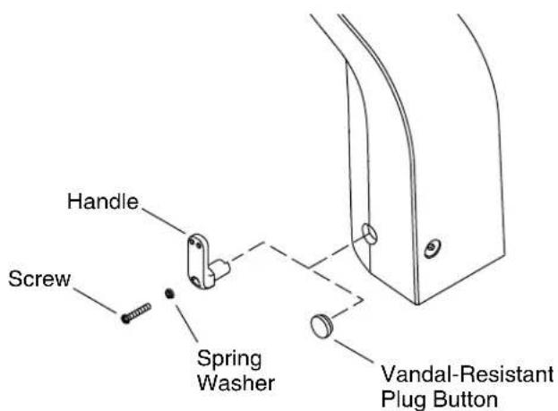
Using the 2.5mm hex wrench provided, remove and retain the handle screw.
- Remove and retain the handle with the spring washer.
1244026-2-A 10 Kohler Co.
Optional Temperature Limiting Adjustment (cont.)
- Insert the handle at the desired maximum temperature. If the handleisinsertedhorizontally: This is the maximum hot temperature, where the water will be the same temperature as the water from the hot water supply. If the handleisinserted vertically(shown): This is the maximum cold temperature, where the water will be the same temperature as the water from the cold water supply.
NOTICE:Do not rotate the handle when reinstalling the screw.
- Reinstall the spring washer into the handle, then attach the handle to the faucet.
- Secure the handle to the faucet with the screw.
Adjust the Water Temperature Limit - Vandal-Resistant Installations
NOTE:If you install the vandal-resistant plug button, save the handle to adjust the water temperature at a later date.
Using the handle, adjust the water to the desired temperature.
Using the 2.5mm hex wrench provided, remove and retain the screw, spring washer, and handle.
Position the vandal-resistant plug button and firmly press into place.
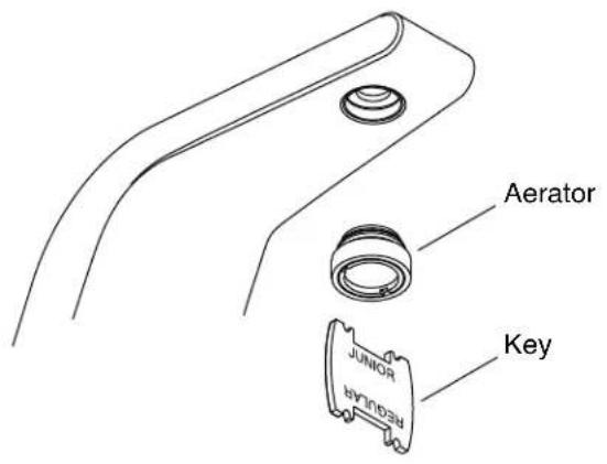
7. Installation Checkout
Using the key provided, remove the aerator from the spout.
If applicable, uncover the drain.
Turn on the water supply and check for leaks. Adjust as needed.
- Allow the water to run through the spout for about 1 minute to remove any debris. Check for leaks and adjust as needed.
- Temporarily cover the sensors on the faucet or close the water supplies.
Using the key provided, reinstall the aerator to the spout.
- Uncover the sensors on the faucet or turn on the water supplies.