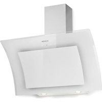
SleekAir - Basket Klarstein - Free user manual and instructions
Find the device manual for free SleekAir Klarstein in PDF.

User questions about SleekAir Klarstein
0 question about this device. Answer the ones you know or ask your own.
Ask a new question about this device
Download the instructions for your Basket in PDF format for free! Find your manual SleekAir - Klarstein and take your electronic device back in hand. On this page are published all the documents necessary for the use of your device. SleekAir by Klarstein.
USER MANUAL SleekAir Klarstein
area
| Category | Value | | -------- | ----- | | 1 | 100 | | 2 | 100 | | 3 | 100 | | 4 | 100 | | 5 | 100 | | 6 | 100 | | 7 | 100 | | 8 | 100 | | 9 | 100 | | 10 | 100 | | 11 | 100 | | 12 | 100 | | 13 | 100 | | 14 | 100 | | 15 | 100 | | 16 | 100 | | 17 | 100 | | 18 | 100 | | 19 | 100 | | 20 | 100 | | 21 | 100 | | 22 | 100 | | 23 | 100 | | 24 | 100 | | 25 | 100 | | 26 | 100 | | 27 | 100 | | 28 | 100 | | 29 | 100 | | 30 | 100 | | 31 | 100 | | 32 | 100 | | 33 | 100 | | 34 | 100 | | 35 | 100 | | 36 | 100 | | 37 | 100 | | 38 | 100 | | 39 | 100 | | 40 | 100 | | 41 | 100 | | 42 | 100 | | 43 | 100 | | 44 | 100 | | 45 | 100 | | 46 | 100 | | 47 | 100 | | 48 | 100 | | 49 | 100 | | 50 | 100 | | 51 | 100 | | 52 | 100 | | 53 | 100 | | 54 | 100 | | 55 | 100 | | 56 | 100 | | 57 | 100 | | 58 | 100 | | 59 | 100 | | 60 | 100 | | 61 | 100 | | 62 | 100 | | 63 | 100 | | 64 | 100 | | 65 | 100 | | 66 | 100 | | 67 | 100 | | 68 | 100 | | 69 | 100 | | 70 | 100 | | 71 | 100 | | 72 | 100 | | 73 | 100 | | 74 | 100 | | 75 | 100 | | 76 | 100 | | 77 | 100 | | 78 | 100 | | 79 | 100 | | 80 | 100 | | Note: The actual values are not provided in the code. I have used the label 'Value' as a placeholder for the value detection. You would need to run the code to get the actual values from the code list. Please note that the actual values would be the result of this example. You would need to run the code to get the actual values from the code list. You would need to run the code to get the actual values from the code list. You would need to run the code to get the actual values from the code list. You would need to run the code to get the actual values from the code list. You would need to run the code to get the actual values from the code list. You would need to run the code to get the actual values from the code list. You would need to run the code to get the actual values from you would need to run the code.text_image
QR code image containing encoded data, no visible human-readable textINHALT
Technische Daten 3
natural_image
Diagram of airflow around a mechanical structure with directional arrows (no text or symbols)Inklusive Installationsmaterial
∅8
7×

∅8
7×

∅8
6×
ST 6,0×40
2×

∅10
2×
natural_image
Diagram of a kitchen appliance with two curved arrows indicating motion, mounted on a rectangular base (no text or symbols)natural_image
Technical line drawing of a rectangular tank with internal components, shown with two circular insets (no text or symbols)natural_image
Diagram of a mechanical assembly with two hanging weights on a brick wall (no text or symbols)natural_image
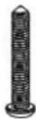
Technical line drawing of a vertical cylindrical device with a hanging lever and base plate (no text or symbols)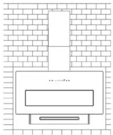
natural_image
Simple line drawing of a kitchen appliance mounted on a brick wall (no text or symbols)natural_image
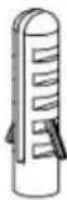
Line drawing of a mechanical device with a handle and internal compartments, no text or symbols presentnatural_image
Diagram of a mechanical assembly with rotating components and a central rod (no text or labels)
natural_image
Line drawing of an open mechanical device with internal components and a lid (no text or symbols)Hinweise
natural_image
Symbol of a trash bin with crossed lines indicating no waste, and a solid black rectangle below (no text or labels)Berlin Brands Group UK Limited
35 Ballards Lane
London, N3 1XW
United Kingdom
Name: Customer service
Website: https://www.elektronik-star.de/lnfo/Impressum/
E-Mail-Adresse: info@electronic-star.de
Telefonnummer: +49303001385500
Anschrift:
Wallstraße 16
10179 berlin
Deutschland
Dear Customer,
Congratulations on purchasing this equipment. Please read this manual carefully and take care of the following hints on installation and use to avoid technical damages. Any failure caused by ignoring the items and cautions mentioned in the operation and installation instructions are not covered by our warranty and any liability. Scan the QR code to get access to the latest user manual and more product information.

text_image
QR code image containing encoded data, no visible human-readable textCONTENTS
Technical Data 25
Safety Instructions 26
Product Dimensions 28
Installation 29
Installing Activated Carbon Filter 35
Operation 36
Cleaning and Maintenance 38
Troubleshooting 40
Disposal Considerations 41
Manufacturer & Importer (UK) 41
TECHNICAL DATA
| Article number | 10046820, 10046821, 10046822, 10046823, 10046824, 10046825 |
| Power supply 220-240 V ~ | 50/60 Hz |
| Power rating 123 W | |
| Motor power 120 W | |
| Lamp 1×3 W |
SAFETY INSTRUCTIONS
- Thank you for purchasing this cooker hood. Please read the instruction manual carefully before you use the cooker hood, and keep it in a safe place.
- The installation work must be carried out by a qualified electrician or competent person. Before you use the cooker hood, make sure that the voltage (V) and the frequency (Hz) indicated on the cooker hood are exactly the same as the voltage and the frequency in your home.
- The manufacturer and the agent will not bear any responsibility for the damage caused by inappropriate installation and usage.
• Children under the age of 8 must not use the cooker hood. - The appliance is not intended for commercial use, but only for household and similar environments.
- The cooker hood and its filter mesh should be cleaned regularly in order to keep it in good working order.
- Before cleaning, switch the power off at the main supply.
- Clean the cooker hood according to the instruction manual and keep the cooker hood from the danger of burning.
• Prohibit putting the cooker hood by fire. - If the appliance does not function normally, contact the manufacturer or a specialist company.
- This device may be only used by children 8 years old or older and persons with limited physical, sensory and mental capabilities and / or lack of experience and knowledge, provided that they have been instructed in use of the device by a responsible person who understands the associated risks.
- If the supply cord is damaged, it must be replaced by the manufacturer, its service agent or similarly qualified persons in order to avoid a hazard.
- If the range hood is used at the same time as appliances burning gas or other fuels, the room must be adequately ventilated.
- Do not flambé under the range hood. Accessible parts may become hot when used with cooking appliances.
Important hints on installation
- The air must not be discharged into a flue that is used for exhausting fumes from appliances burning gas or other fuels (not applicable to appliances that only discharge the air back into the room).
- Regulations concerning the discharge of air have to be fulfilled.
Important notes about the extraction mode

WARNING
Risk of poisoning from exhaust gases sucked back. Never operate the device in extraction mode simultaneously with an open flue appliance when there is not adequate airflow guaranteed.
Open flue combustion equipment (for example, gas, oil, wood or coal-fired heaters, tankless water heaters, water heaters) pulls combustion air from the room and runs it through an exhaust pipe or chimney to the outside. In the extraction mode, indoor air is removed from the kitchen and the adjacent rooms - without sufficient air intake this creates a vacuum. Toxic gases from the chimney or extraction flue can thereby be sucked back into the living spaces.
• Always ensure that a sufficient supply of fresh air is guaranteed and that the air can circulate.
- An air supply / extractor box alone does not ensure compliance with the limit value.
Safe operation is only possible when the negative pressure in the room where the appliance is located does not exceed 4 Pa (0.04 mbar). This can be achieved when the air required for combustion can flow through openings that are not closable, for example in doors, windows, in conjunction with an air supply / extractor box or through other technical measures. In any case, consult a qualified chimney sweep who can assess the entire ventilation of your house and propose appropriate measures for adequate ventilation.
If the hood is used exclusively in the recirculation mode, unrestricted operation is possible.
Important note on disassembly of the device
- Disassembly is similar to installation/assembly in reverse order.
• Take a second person to help you during disassembly to avoid injuries.
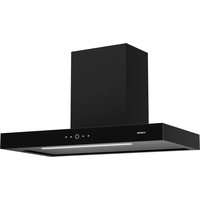
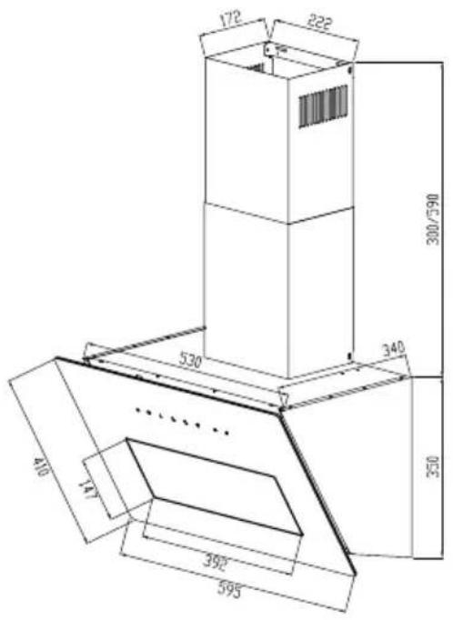
PRODUCT DIMENSIONS
60 cm
text_image
172 222 300/590 530 340 350 410 11 392° 595°90 cm
text_image
172 222 300/590 340 616 410 147 692 896 350INSTALLATION
Installation with exhaust air
Note: Observe the safety instructions for operating the unit when the air is discharged to the outside. If the cooker hood is in operation at the same time as an appliance that draws its energy from a source other than electricity, the negative pressure in the room must not exceed 4 Pa (4 x 10⁻⁵ bar).
Installation with convection function
If you do not have an outdoor extractor, you do not need an exhaust air pipe. The installation corresponds to installation with external ventilation.
Preparation
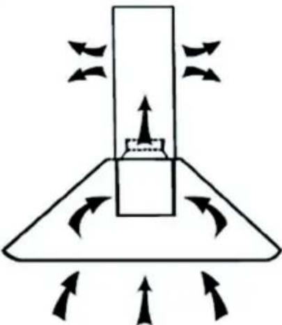
If you have an extractor to the outside, you can install the extractor hood as shown in the picture on the right.
The flue should have a diameter of at least 150 mm and be made of enamel, aluminium or a flexible, heat-resistant tube.
- Switch off the device before installation and pull the power plug out.
- The extractor hood should be placed at a height of 65-75 cm above the hob.
natural_image
Diagram of airflow around a mechanical structure with directional arrows indicating movement (no text or symbols)During installation, the minimum distance between the hob and the cooker bonnet must be strictly observed and the numbering of the work steps as well as the additional instructions must be followed.
Installation with exhaust air to the outside
The vapours are extracted with an exhaust air hose attached to the connection ring.
The diameter of the exhaust hose must match the diameter of the connection ring. If a smoke check valve is used or planned, it must be checked that it can be opened and closed easily after the exhaust air hose has been installed. The cooker hood can be equipped with one (top) or two (top and rear) exhaust openings.
Generally, the cooker bonnet is initially equipped for use of the upper extractor opening as a extractor bonnet. The openings that are not needed are covered with a plastic cover. This plastic cover can be easily removed by turning it anticlockwise and optionally attached to another opening that is not needed.
Installation of range hood
Hardware included

∅8
7×
∅8
7×

∅8
6×

ST 6.0×40
2×
∅10
2×
Installing steps
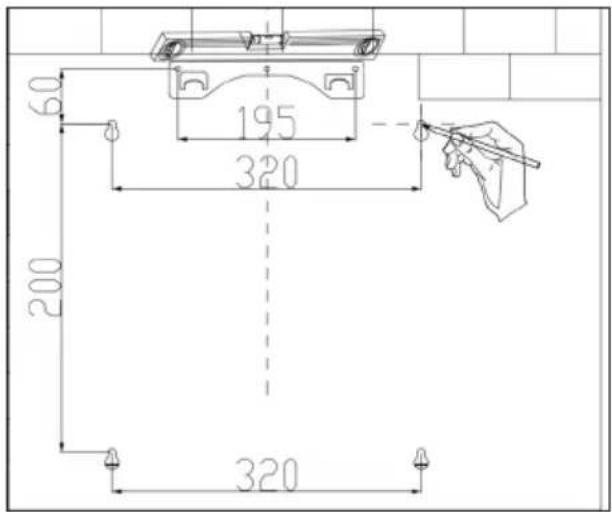
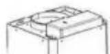
Determine the position of the mounting plate according to the following figure.
60 cm installation size
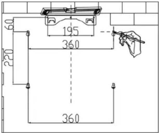
text_image
60 195 360 220 36090 cm installation size
text_image
60 195 320 200 320Drill 3 holes on the wall for installing the mounting plate. Then install the mounting plate onto the wall.
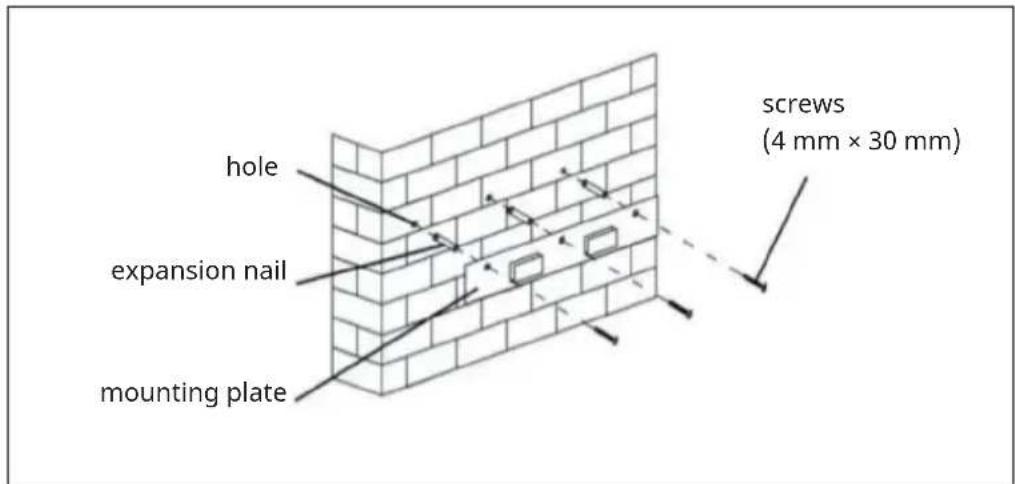
text_image
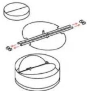
hole expansion nail mounting plate screws (4 mm × 30 mm)Hang the range hood onto the mounting plate. Remove the filters and mark the positions of the other two safety screws on the wall from inside the hood.
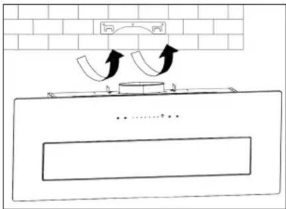
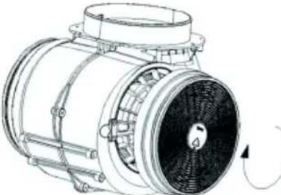
natural_image
Diagram of a kitchen appliance with two curved arrows indicating motion, mounted on a base (no text or symbols)Remove the range hood from the mounting plate, drill holes for safety screws in the wall, and insert expansion nails.
text_image
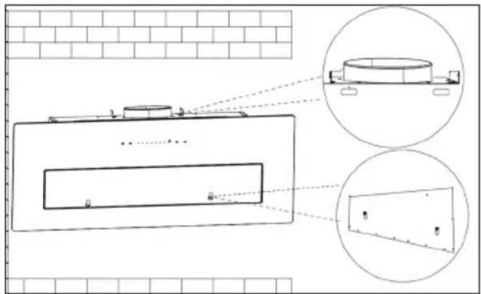
Technical diagram showing a tank with internal components and two circular insets highlighting different storage tanks.- Hang the hood mounting plate again and fix it to the wall with 2 screws.
- Install the filters.
• Install the exhaust pipe to the outlet of air on top of hood.
Chimney installation

text_image
Exhaust air Circulating air upper part of the chimney (inside) wall mount lower part of the chimney (outside)-
Slide the upper chimney section into the lower chimney section. Pay attention to the position of the ventilation slots - depending on the use for exhaust or recirculation (see illustration).
-
Attach the lower wall bracket to the lower part of the chimney.
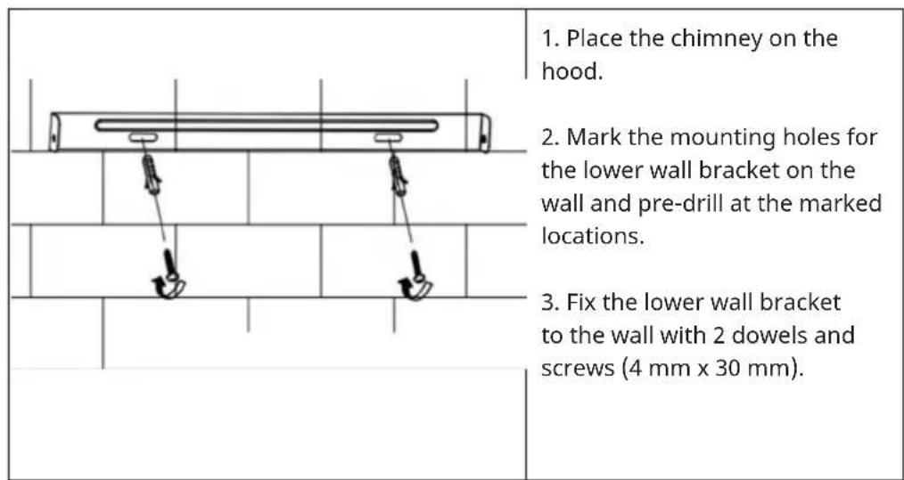
text_image
1. Place the chimney on the hood. 2. Mark the mounting holes for the lower wall bracket on the wall and pre-drill at the marked locations. 3. Fix the lower wall bracket to the wall with 2 dowels and screws (4 mm x 30 mm).
text_image
dowel wall mount screw 4 mm × 8 mm screw 4 mm × 30 mm- Pull out the upper part of the chimney to the desired height.
- Mark the mounting holes for the upper wall bracket on the wall and pre-drill at the marked locations.
- Fix the upper wall bracket to the drilled positions on the wall using 2 dowels and 2 screws ST4 x 30 mm.
- Fasten the upper part of the chimney to the wall bracket with 2 screws ST4 x 8 mm.
natural_image
Technical line drawing of a vertical mechanical device with a suspended load and base plate (no text or symbols)
natural_image
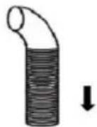
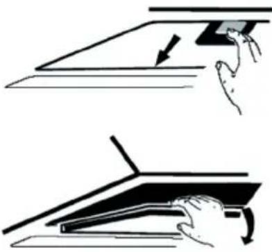
Line drawing of a kitchen appliance mounted on a brick wall (no text or symbols)Note: Push in from the above to open the glass panel.
natural_image
Line drawing of a mechanical device with a handle and internal structure, no text or symbols present- The angle of the bend of the exhaust air pipe should not be less than 120^ . Align the pipe horizontally. Alternatively, the pipe should go up from the starting point and be led to an outer wall.
• After installation, make sure that the cooker hood is horizontal in order to prevent grease from collecting on one side. - Make sure that the exhaust duct selected for installation complies with the relevant standards and is fire resistant.
Fastening the exhaust pipe
Note: The Vent pipe is not a standard accessory and has to be purchased separately. Remove the protective film before installation.
Valve installation
• Fix the one-way-valve to the air outlet of the range hood.
• Install the one-way valve to the fume hood air outlet. Then install the exhaust pipe to the one-way valve as shown in the picture.
natural_image
Diagram showing three circular components with internal structures and directional arrows, no text or symbols present.exhaust air pipe
range hood
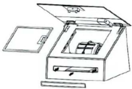
INSTALLING ACTIVATED CARBON FILTER
| 1 | 2 |
 |  |
| With an activated carbon filter, unpleasant food odours can be filtered out of the air in internally vented extractor hoods. | To be able to install the filter, you must first remove the grease filter. Press the fastener and pull it down. |
| 3 | |
 | Put the activated carbon filter on the fan and turn it clockwise to tighten. Repeat the procedure on the other side. Make sure the filter is tight, otherwise it could come loose and pose a hazard. Note: If an activated carbon filter is installed, the extraction performance decreases slightly. |
OPERATION
Control panel
 | Turn on/off |
| [4AB3] | Turn light on/off |
 | Fan level 1 |
| [0CSH] | Fan level 2 |
 | Fan level 3 |
 | Booster mode |
 | Timer button |
 | Air cleaning function button |
Starting the unit and Stopping the Unit
In standby mode, long press the ON/OFF button to switch on the cooker hood, in working mode, long press the ON/OFF button to close on the cooker hood.
Note: The LED on this button will remain off while the cooker hood fan is operating. Conversely, it will be illuminated when the fan is not running, and the LED colour will be red.
LED light
Briefly press the LIGHT button to switch the light on. Press the button again to switch the light off.
Light temperature adjustment/light brightness adjustment
In standby mode, perform a 3-second long press on LIGHT button to access the light temperature adjustment function. Upon entering the light temperature adjustment state, the LEDs on both the button first speed and button third speed will flash simultaneously. At this point, you can use the button first speed or the button third speed to regulate the light temperature. The range of adjustable light
temperature spans from 3200K for a warm colour tone to 6500K for a cooler colour tone, all within a cycle (press the button first speed to decrease, press the button third speed to increase).
Once you have entered the light temperature adjustment mode, you can conveniently modify the light's brightness by giving the button light a brief press. The brightness follows a sequence of 100% - 75% - 50% - 75% - 100%. After confirming your preferred light temperature and brightness settings, execute a long press on the button light to exit the adjustable light temperature mode. The initial default light temperature is set to 3200K for a warm colour tone.
Booster
Short press Booster button to activate Boost 1, the button will flash slowly. Long press to activate Boost 2, the button will flash rapidly. After the Boost has operated for 5 minutes, the speed automatically reverts to level 3 speed.
Timer
Timer button, short press it and will into 5 minutes countdown. After 5 minutes, the fan motor and light will turn off automatically and there is a beep.
Air cleaning function
In standby mode, long press the button to activate, the indicator light will turn on in green colour. This function automatically shuts down after 5 minutes of low-speed operation. After 55 minutes of stopping, it automatically runs again for 5 minutes and then stops again for 55 minutes. Once this function is enabled, it can only be deactivated by pressing the button for 1 second.
This deactivation does not have an impact on the normal operations. During the 55 minutes in operation phase, the LED button will flash green, when the 55 minutes on OFF period starts, the button LED will emit a steady green light.
Should the air cleaning been gauged and the fan manually switched on, the air cleaning function will halt automatically. However, upon turning off the fan, the air cleaning function will automatically resume.
CLEANING AND MAINTENANCE
WARNING
Risk of electric shock! Do not use a steam cleaner for the cleaning.
- Make sure that the appliance is switched off.
- Unplug the appliance before cleaning it.
• Always allow the appliance and its components to cool down before cleaning them. - Do not use cloths, chemicals or alcohol for cleaning as these may damage the surface. Electrical/electronic parts must not be cleaned.
- Do not use harsh or corrosive cleaning agents. Do not use abrasive cleaning agents or alkaline rinsing agents (pH value above 7).
- Maintenance and inspection should be carried out regularly. In case of visible damage, strong odour or excessive overheating of components, stop using the appliance.
- Clean the appliance according to the instructions. There is a fire hazard if this is not observed.
Stainless steel surfaces
Clean the stainless steel surface weekly. For cleaning, use a soft cloth and lukewarm water and use a cleaning agent suitable for stainless steel. Make sure you wipe along the grain of the stainless steel to avoid unsightly scratches.
Control panel interface
Clean the control panel surface weekly. Use a soft cloth and lukewarm water for cleaning. Make sure that the cloth is clean and not too wet before cleaning. Wipe away excess moisture with a dry, soft cloth.
Monthly cleaning of the grease filters
Clean the filter every month to avoid a fire hazard. The filter collects grease, smoke and dust and thus influences the efficiency of the cooker hood. If the filter is not cleaned, grease residues will collect there.
To clean the grease filters:
- Remove the grease filter.
- Manual cleaning (max. 30 °C): Soak the filter in water with a mild, non-caustic grease-dissolving detergent for about 3 minutes.
- Cleaning in the dishwasher (max. 30 °C): Place the filter in the dishwasher and run a programme with a mild, non-caustic, grease-dissolving detergent.
Replacing the light
• The light may only be replaced by a qualified electrician.
- Before opening the device, unplug all power connections.
• Always allow the light to cool down before replacing it.
• Always use gloves or a cloth to avoid direct contact with your hands. Direct contact can shorten the life of the light.
- Push the LED light out and replace the LED lighting.
natural_image
Line drawing of an open toolbox with internal compartments and a car (no text or symbols)Notes
- Make sure to reattach everything after inserting the new light and put all the screws in the same position.
• Always replace the lamp with a lamp of the same type and amperage.
TROUBLESHOOTING
| Problem Potential cause | Solution | |
| The light turns on but the motor does not run. | The ventilation is blocked. | Remove the blockage. |
| The capacitor is broken. Have the capacitor replaced. | ||
| The motor is broken. Have the motor replaced. | ||
| The motor smells strange. | Have the motor replaced. | |
| The light is off and the motor does not run. | The light is broken. Have the light replaced. | |
| The plug is loose. Plug the power plug securely into the wall socket. | ||
| The housing vibrates. The | rotor blade of the fan is damaged. | Replace the blade. |
| The motor is not firmly seated. | Fasten the motor. | |
| The casing is loosely hanging. | Fasten the housing. | |
| The air is not being properly extracted. | The distance between the cooker and the extractor hood is too far. | Reduce the distance. |
| Too much air circulation through open windows and doors. | Make sure that there is no draught. | |
DISPOSAL CONSIDERATIONS
natural_image
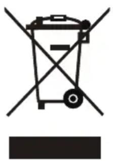
Symbol of a trash bin with crossed lines indicating no waste or discharge, and a solid black rectangle below (no text or labels)If there is a legal regulation for the disposal of electrical and electronic devices in your country, this symbol on the product or on the packaging indicates that this product must not be disposed of with household waste. Instead, it must be taken to a collection point for the recycling of electrical and electronic equipment. By disposing of it in accordance with the rules, you are protecting the environment and the health of your fellow human beings from negative consequences. For information about the recycling and disposal of this product, please contact your local authority or your household waste disposal service.
This product contains batteries. If there is a legal regulation for the disposal of batteries in your country, the batteries must not be disposed of with household waste. Find out about local regulations for disposing of batteries. By disposing of them in accordance with the rules, you are protecting the environment and the health of your fellow human beings from negative consequences.
MANUFACTURER & IMPORTER (UK)
Manufacturer:
Chal-Tec GmbH, Wallstrasse 16, 10243 Berlin, Germany.
Contact: info@electronic-star.de
Importer for Great Britain:
Berlin Brands Group UK Limited
35 Ballards Lane
London, N3 1XW
United Kingdom
Contact: info@electronic-star.de
Product fiche
Delegated Regulation (EU) 65/2014
| Supplier name or trademark Klarstein | |
| Model identifier | 10046820, 10046821, 10046822, 10046823, 10046824, 10046825 |
| Annual Energy Consumption 17,7 kWh/annum | |
| Energy Efficiency Class A+++ | |
| Fluid Dynamic Efficiency 40,4 | |
| Fluid Dynamic Efficiency class A | |
| Lighting Efficiency 40,0 Lux/W | |
| Lighting Efficiency class A | |
| Grease Filtering Efficiency 67,3 % | |
| Grease Filtering Efficiency class D | |
| Air flow (min speed normal use) 207 m3/h | |
| Air flow (max speed normal use) 385 m3/h | |
| Air flow (intensive or boost use) 717 m3/h | |
| Airborne acoustical A-weighted sound power emissions (min speed normal use) | 39 dB |
| Airborne acoustical A-weighted sound power emissions (max speed normal use) | 54 dB |
| Airborne acoustical A-weighted sound power emissions (intensive or boost use) | 66 dB |
| Power consumption in off mode (W) 0,48 W |
Model placed on the Union market from 01/04/2025.

EPREL registration number: 2294867
https://eprel.ec.europa.eu/qr/2294867
Supplier: Chal -Tec GmbH (Authorised representative)
Website:
Customer care service:
Name: Customer service
Website: https://www.elektronik-star.de/lnfo/Impressum/
Email: info@electronic-star.de
Phone: +49303001385500
Address:
Wallstraße 16
10179 berlin
Germany
Chère cliente, cher client,
text_image
QR code image containing encoded data, no visible human-readable textSOMMAIRE
Fiche technique 45
DIMENSIONS DU PRODUIT
60 cm
text_image
172 222 300/590 530 340 350 110 17 392 59590 cm

text_image
172 222 300/590 340 616 410 147 692 895 350INSTALLATION
natural_image
Diagram of airflow around a mechanical structure with directional arrows indicating movement (no text or symbols)natural_image
Diagram of a kitchen appliance with two curved arrows indicating motion, mounted on a base plate (no text or symbols)text_image
Technical diagram showing a tank with internal components and two circular insets highlighting different storage tanks.text_image
Diagram showing a house inside a double door with an arrow indicating downward motion, enclosed in a dashed box.natural_image
Diagram of a mechanical assembly with two hanging weights on a brick wall (no text or symbols)text_image
cheville support mural vis 4 mm × 8 mm vis 4 mm × 30 mmnatural_image
Line drawing of a vertical cylindrical device with a hanging lever and base plate (no text or symbols)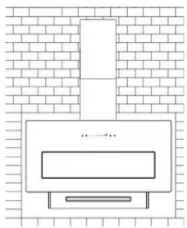
natural_image
Simple line drawing of a portable stove or oven with a chimney, set against a brick wall background (no text or symbols)natural_image
Line drawing of a mechanical device with a handle and internal structure, no text or symbols presentnatural_image
Diagram showing three circular components with internal structures and directional arrows, no text or symbols present.natural_image
Line drawing of an open mechanical device with internal components and a lid (no text or symbols)Remarques
natural_image
Symbol of a trash bin with crossed lines and a horizontal bar below (no text or labels)Berlin Brands Group UK Limited
35 Ballards Lane
London, N3 1XW
United Kingdom
Nom: Customer service
Site web: https://www.elektronik-star.de/lnfo/Impressum/
Courriel: info@electronic-star.de
Téléphone: +49303001385500
Adresse:
Wallstraße 16
10179 berlin
Allemagne
Gentile cliente,
text_image
QR code image containing encoded data, no visible human-readable textINDICE
Dati tecnici 65
natural_image
Diagram of airflow around a mechanical structure with directional arrows indicating movement (no text or symbols)natural_image
Diagram of a kitchen appliance with two curved arrows indicating motion, mounted on a base plate (no text or symbols)text_image
Technical diagram showing a tank with internal components and two circular insets highlighting different storage tanks.text_image
Diagram showing a house with a downward arrow inside a box, indicating a decrease or reduction in height.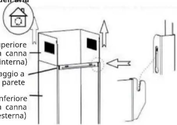
text_image
periore canna nterna) aggio a parete inferiore canna sterna)natural_image
Diagram of a mechanical assembly with two hanging weights and a cylindrical rod mounted on a brick wall (no text or symbols)natural_image
Technical line drawing of a vertical cylindrical device with a suspended arm and base plate (no text or symbols)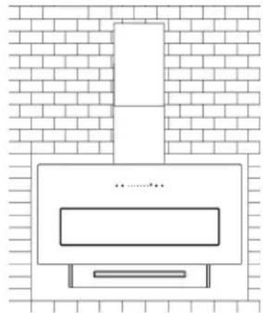
natural_image
Simple line drawing of a kitchen appliance on a brick wall (no text or symbols)natural_image
Line drawing of a mechanical device with a handle and internal compartments, no text or symbols presentIT
text_image
Diagram showing a mechanical or optical setup with labeled components and directional arrows, possibly illustrating a physics or engineering concept.natural_image
Line drawing of an open mechanical device with internal components and a lid (no text or symbols)Note
natural_image
Symbol of a trash bin with crossed lines indicating no waste or discharge, and a solid black rectangle below (no text or labels)Berlin Brands Group UK Limited
35 Ballards Lane
London, N3 1XW
United Kingdom
Nome: Customer service
Sito web: https://www.elektronik-star.de/lnfo/Impressum/
E-mail: info@electronic-star.de
text_image
QR code image containing encoded data, no visible human-readable textÍNDICE
Datos técnicos 85
DIMENSIONES DEL PRODUCTO
60 cm

text_image
172 222 300/590 530 340 350 110 17 392 59590 cm

text_image
172 222 300/590 340 616 410 147 692 895 350INSTALACIÓN
natural_image
Diagram of airflow around a mechanical structure with directional arrows (no text or symbols)natural_image
Diagram of a kitchen appliance with two curved arrows indicating motion, mounted on a base plate (no text or symbols)text_image
Technical diagram showing a tank with internal components and two circular insets highlighting different storage tanks.natural_image
Technical line drawing of a vertical cylindrical device with a suspended arm and base plate (no text or symbols)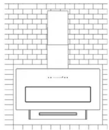
natural_image
Simple line drawing of a kitchen appliance with a chimney and gridded brick wall background (no text or symbols)natural_image
Line drawing of a mechanical device with a handle and internal compartments, no text or symbols presenttext_image
Diagram illustrating a mechanical or electrical setup with labeled components and directional arrows, likely from an engineering or physics context.natural_image
Line drawing of an open wooden box with internal compartments and a lid, no text or symbols presentNotas
natural_image
Symbol of a trash bin with crossed lines and a horizontal bar below (no text or labels)Berlin Brands Group UK Limited
35 Ballards Lane
London, N3 1XW
United Kingdom