BK49BS - Beer dispenser HomeCraft - Free user manual and instructions
Find the device manual for free BK49BS HomeCraft in PDF.

| Product Type | Beer Dispenser (Kegerator) |
| Brand | HomeCraft |
| Model | BK49BS |
| Dimensions (W x D x H) | 63 cm x 51 cm x 85 cm |
| Weight | 41 kg |
| Power Supply | 115 V, 60 Hz, 90 W |
| Capacity | 4,9 ft³ (138 L) |
| Keg Compatibility | 1/2 barrel, 1/4 barrel, 1/4 slim barrel, 1/6 barrel |
| CO2 Tank | 1,13 kg (2,5 lb) empty |
| Recommended Service Pressure | 8–12 PSI |
| Ideal Serving Temperature | 3 °C (37 °F) |
| Main Features | Beer dispensing, convertible to refrigerator |
| Safety | Mandatory grounding, pressure relief valve, child safety lock |
| Maintenance | Cleaning beer lines and faucet after each use |
| Included Parts | Keg tower, D-Sankey coupler, regulator, CO2 tank, casters (2 lockable), grilles (2), guard rail, drip tray |
| Warranty | 1 year |
Frequently Asked Questions - BK49BS HomeCraft
User questions about BK49BS HomeCraft
0 question about this device. Answer the ones you know or ask your own.
Ask a new question about this device
Download the instructions for your Beer dispenser in PDF format for free! Find your manual BK49BS - HomeCraft and take your electronic device back in hand. On this page are published all the documents necessary for the use of your device. BK49BS by HomeCraft.
USER MANUAL BK49BS HomeCraft
All products are trademarks of Nostalgia Products LLC.
Worldwide design & utility patented or patents pending.
© 2020 Nostalgia Products LLC.
www.nostalgiaproducts.com
(rev. 03/04/20 MD)

natural_image
Black HomeCraft-branded refrigerator with a vertical chimney and metal frame (no visible text or symbols on the device body)KEGERATOR™
Instruction Manual
Your safety and the safety of others is very important.
We have provided many important safety messages in this manual and on your appliance. Always read and obey all safety messages.

This is the safety alert symbol.
This symbol alerts you to potential hazards that can cause serious injury to you and others.
All safety messages will follow the safety alert symbol.
All safety messages will tell you what the potential hazard is, tell you how to reduce the chance of injury, and tell you what can happen if the instructions are not followed.
Appliance Specifications:
90 W, 115 V, 60 Hz


IMPORTANT SAFEGUARDS
A person who has not read and understood all operating and safety instructions is not qualified to operate this appliance. All users of this appliance must read and understand this Instruction Manual before operating or cleaning this appliance.
When using electrical appliances, basic safety precautions should always be followed, including:
- Read all instructions before operating this appliance.
- DO NOT TOUCH the hot surfaces. Use handles or knobs.
- This appliance is NOT A TOY.
- Keep out of reach of children.
- Unsupervised young children and cognitively challenged individuals should never operate this appliance.
- Close supervision is necessary when any appliance is used by or near children.
- To protect against electrical shock do not immerse cord, plug or any part of this unit in water or other liquids.
- Do not operate this appliance when parts are missing or broken.
- Unplug from outlet when not in use, before removing parts and before cleaning. Allow to cool before putting on or taking off any parts, and before cleaning.
- DO NOT operate any appliance with a damaged cord or plug, or after the appliance malfunctions, or if the appliance has been damaged in any manner. Return the appliance to the nearest repair shop for examination, repair or adjustment.
- The manufacturer does not recommend the use of accessory attachments other than what is provided by the manufacturer. Use of attachments may cause injuries.
- DO NOT use the appliance for other than its intended use.
- DO NOT use outdoors. FOR HOUSEHOLD USE ONLY.
- DO NOT place on or near a hot gas or electric burner, or in a heated oven.
- DO NOT put any parts of this appliance in dishwasher.
- DO NOT let cord hang over edge of table or counter, or touch not surfaces.
- NEVER leave unit unattended while in use or when plugged into an outlet.
- Extreme caution must be used when moving an appliance containing hot food.
- Always attach plug to appliance first, then plug cord in the wall outlet. To disconnect, turn any control to "off," then remove plug from wall outlet.

ADDITIONAL IMPORTANT SAFEGUARDS
Operating Safety Precautions
- Before discarding your old appliance, remove the door from its hinges so that children may not easily become trapped inside.
- DO NOT roll the KEGERATOR™ with loaded beer kegs onto carpet floor.
- The appliance door must be closed during operation. DO NOT leave the door open when children are near.
-
This appliance should not be recessed or built into an enclosed cabinet. It is designed for freestanding assembly only.
-
Do not operate your appliance in the presence of explosive fumes.
- Do not tamper with the controls.
Instructions for the Electrical Cord and Plug
-
ELECTRICAL SHOCK HAZARD: Failure to follow these instructions can result in death, fire, or electrical shock.
-
Plug into a grounded 3 prong outlet.
• DO NOT remove ground prong.
• DO NOT use an adapter.
• DO NOT use an extension cord. -
This unit MUST be grounded. In the event of an electrical short circuit, grounding reduces the risk of electric shock by providing an escape wire for the electric current. This unit is equipped with a cord having a grounding wire with a grounding plug. The plug must be plugged into an outlet that is properly installed and grounded.
- WARNING: Improper use of the grounding plug can result in a risk of electric shock. If the plug does not fit fully into the outlet, contact a qualified electrician. Do not attempt to modify the plug in any way.
- A short power supply cord is provided to reduce the risk resulting from becoming entangled or tripping over a long cord.
- The manufacturer does not recommend using this machine in countries that do not support 120V AC even if a voltage adapter, transformer, or converter is in use.
CO _2 (Carbon Dioxide) Gas
- CO 2 gas can be dangerous! CO 2 cylinders contain high-pressure compressed gas, which can be hazardous if not handled properly. Make sure you read and understand all the procedures for the CO _2 cylinders before installation.
- Always connect the CO _2 cylinder to a regulator! Failure to do so may cause an explosion resulting in possible death or injury when the cylinder valve is opened,
- Never connect the CO 2 cylinder directly to the beer keg.
- Always follow the correct procedures when changing the CO 2 cylinder.
- Never drop or throw a CO 2 cylinder.
- Always keep CO _2 cylinders away from heat. Store extra cylinders in a cool place (preferably 70° F). Secure fasten with a chain in an upright position when storing.
- ALWAYS ventilate and leave the area immediately if CO 2 leakage has occurred.
- There are two safety devices in the pressure system in the form of a valve. One safety feature is on the CO_2 bottle. The second is on the regulator.
- Never attempt to refill CO 2 cylinder yourself.
- IMPORTANT! If the refrigerator has been placed in a horizontal or tilted position for any period of time wait 8 hours before plugging in the unit.
SAVE THESE INSTRUCTIONS!
INTRODUCTION
Great for serving even the thirstiest crowd, the HomeCraft™ KEGERATOR™ keeps the beer owing and the good times rolling. This unit adds a unique element to backyard barbecues, garage hangouts, recreation rooms, or simply relaxing at home.
Proper Location
To ensure that your KEGERATOR ^™ works to the maximum efficiency for which it was designed, keep it in a location where there is proper air circulation and electrical outlets.
Choose a location where the KEGERATOR ^™ will be away from heat and will not be exposed to direct sunlight.
- Indoor use only. It should not be used outdoors.
- Designed to be freestanding and should not be placed in a built-in or recessed area.
- Unit includes a 2.5 lb. CO _2 bottle, which should be able to dispense two to four 15 gallon kegs of beer.
- Capacity: 4.9 cu. ft.
- Unit dimensions: L 24.80" x W 20.08" x H 33.50"
- The following dimensions are recommended for clearances around the KEGERATOR™: Sides .... 34 " (19 mm) Back .... 1" (25 mm)
- Unit weight: 90.4 lbs
Compatible Keg Types
The KEGERATOR™ can hold one BarrelFull Size Keg, or one Pony Keg, or two 5-Gallon Kegs. DOES NOT t non-standard keg sizes.
NOTE: Keg Coupler only ts D-Sankey Keg Valves. Attaching the Keg Coupler will add height to the Keg.

bar
| Barrel Type | Height (inches) | | ------------------------ | --------------- | | Sixth Barrel | 23 3/8" | | Quarter Barrel (Pony Keg) | 13 7/8" | | Slim Quarter Barrel (Tall Keg) | 23 3/8" | | ½ Barrel (Full Size) | 23 3/8" | | Bottom Bag (Bottom Height)| 9 1/4" | | Bottom Bag (Bottom Height)| 16 1/8" | | Bottom Bag (Bottom Height)| 11 1/8" | | Bottom Bag (Bottom Height)| 16 1/8" || Kegs 1/6 Barrel | 1/4 Barrel Short 1/4 | Barrel Slim 1/2 Barrel | ||
| Gallons 5.23 7 | 75 7.75 15.50 | |||
| Keg Capacity 1 | 1 1 1 | |||
| 12 oz. Beers 55 | 82 82 | 165 | ||
| Weight (Full in lbs.) | 58 87 87 | 161 |
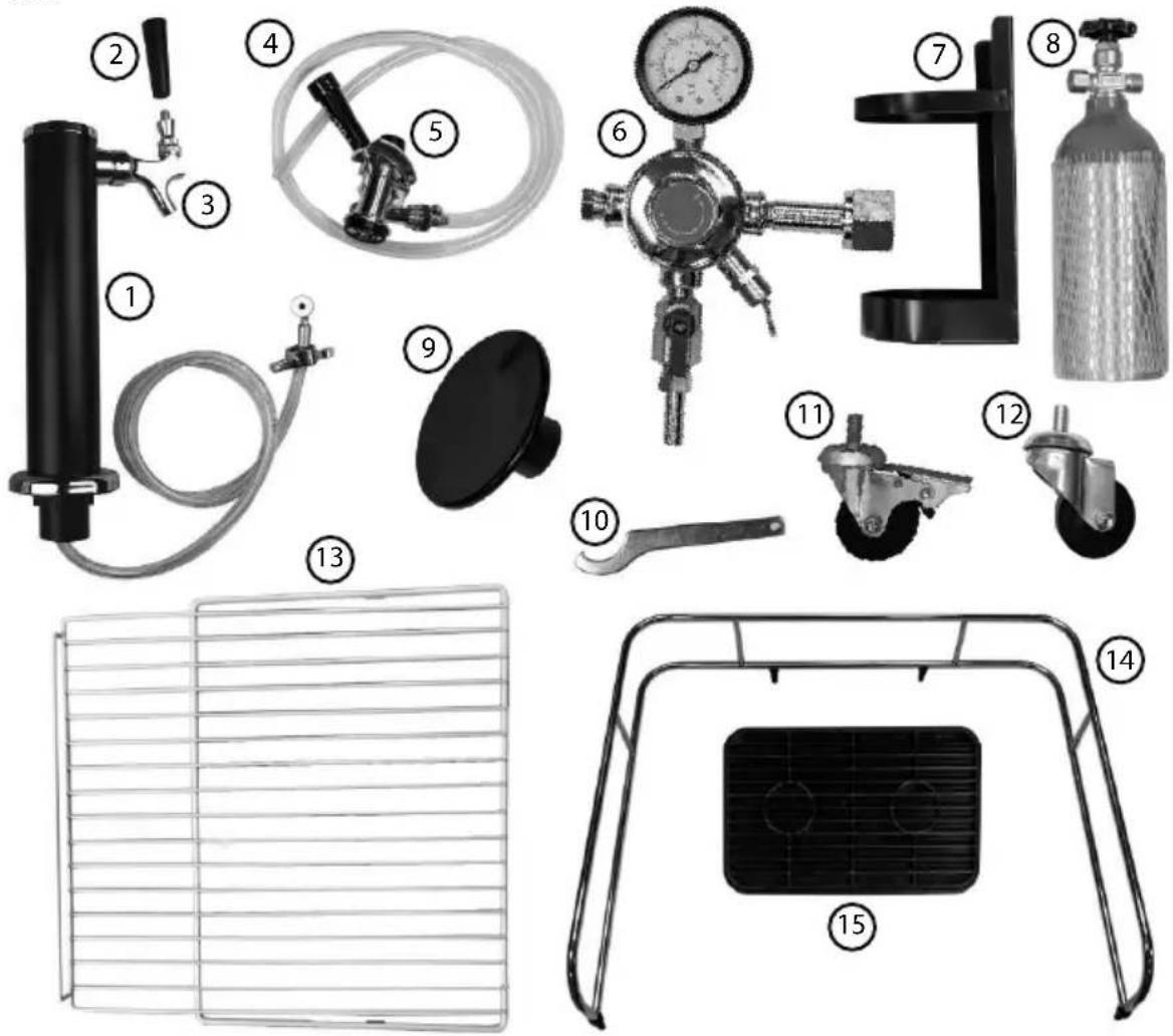
PARTS
Read all instructions carefully before assembling the KEGERATOR ^TM .
IMPORTANT! Stand the KEGERATOR ^™ in an upright position for 8-10 hours before plugging into an electrical outlet. This will allow the coolant in the refrigeration unit to stabilize before turning on the power.
If still unsure whether your KEGERATOR™ has been properly assembled, it is recommended that you contact customer service, or a qualified installer, such as a brewery or wherever kegs are sold.
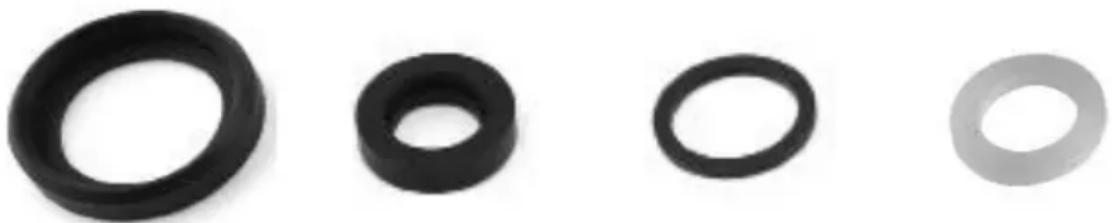
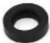
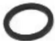
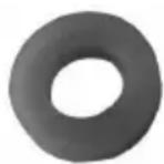
Washers / Beer Line Adapter Parts
NOTE: Most washers are already attached to the KEGERATOR™. Extra parts are included in a plastic bag. Refer to the parts diagram and corresponding part numbers to understand where each washer / extra parts belong.
natural_image
Four different types of black plastic washers or rings, arranged horizontally (no text or symbols visible)Body Seal Coupler Washer (38 mm) (Part 5)
Probe Seal Coupler Washer (22 mm) (Part 5)
Inner Probe Seal
Coupler Washer
(23 mm)
(Part 5)

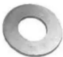
Top Coupler Washer (20 mm) (Part 5)


Tap Tower Spigot Washer (13 mm) (Part 3)
Regulator High Pressure Washer (18 mm) (Part 6)
Tap Tower Washer
(24 mm)
(Part 1)
Spigot Handle Washer
(15 mm)
(Part 2)

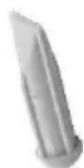
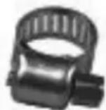

Hose Clamps (Part 4)
CO _2 Hole Plug (Exterior Cabinet)
CO _2 Directional Washer (Part 5)
Backflow Stopper (Part 5)

Metal Washer Qty. 2 (Part 11)
Tap Tower Washer (Part 1)
Parts
text_image
Exploded view diagram of automotive air lift components with numbered labels for identification| (1) Tap Tower Qty. 1 | (2) Spigot Handle Qty. 1 | (3) Tap Tower Spigot Qty. 1 | (4) CO2 Line Qty. 1 |
| (5) Keg Coupler (US Sankey D-System) Qty. 1 | (6) Regulator Qty. 1 | (7) CO2 Tank Holder Qty. 1 | (8) CO2 Tank (unfilled) Qty. 1 |
| (9) Top Cabinet Plug Qty. 1 | (10) Tap Tower Wrench Qty. 1 | (11) Front Locking Casters Qty. 2 | (12) Rear Non-Locking Casters Qty. 2 |
| (13) Wire Shelf Qty. 2 | (14) Guard Rail Qty. 1 | (15) Drip Tray Qty. 1 |
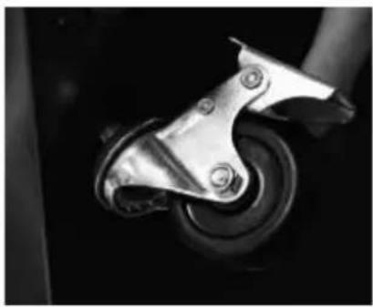
INSTALLING THE CASTERS
NOTE: Each of the Front Casters include a locking mechanism to ensure the unit does not roll on hard floors. The Front Casters should be fastened at the front end of the unit, with the Non-Locking Rear Casters fastened on the rear end.
- Empty the inside of the cabinet and lay the unit down on it's side. To prevent dents or scratches, we recommend placing a piece of cardboard or cloth underneath the cabinet.
- For the Front Casters, place Metal Washers over the Caster bolts, then insert the Casters into the holes on the bottom corners of the cabinet. (The Rear Casters do not require Metal Washers.) Tighten each Caster by turning each metal bracket clockwise.
- Once all four Casters have been tightened, stand the cabinet in the upright position.
Locking The Front Casters
natural_image
Close-up of a metallic mechanical component with bolts, no visible text or symbols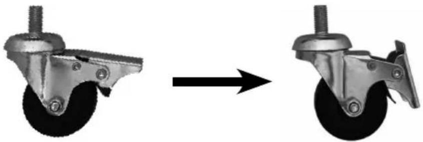
natural_image
Two views of a mechanical casket being processed, showing before and after motion (no text or symbols)Unlocked Locked
ASSEMBLY OVERVIEW

text_image
Tap Tower Regulator CO2 Line Keg Coupler CO2 TankTAP TOWER INSTALLATION
1.
Remove all packing tape from the Tap Tower.
2.
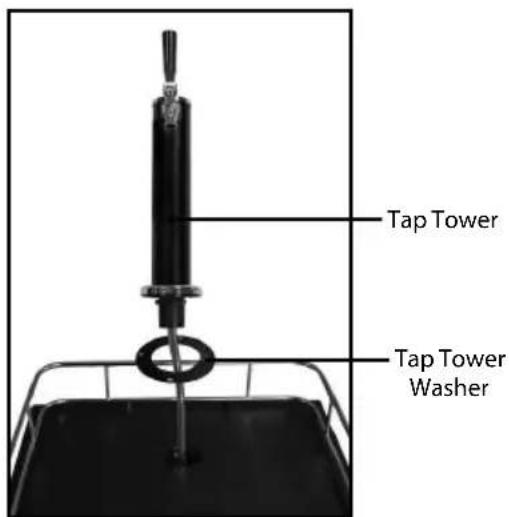
text_image
Tap Tower Tap Tower WasherGuide the Tap Tower Washer up the tap tower hose and let it sit on the top of the cabinet. Then feed the tap tower hose through the hole in the top of the cabinet.
3.
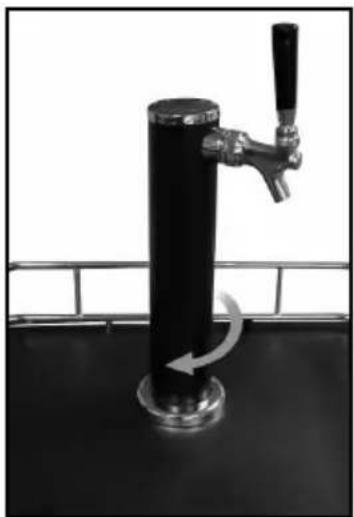
natural_image
Black and white photo of a tall water tap with a handle, mounted on a metal stand (no text or symbols visible)Align the notches at the bottom of the tower with the hole in the top of the cabinet, then insert and twist the tower clockwise to lock it into place (about a 14 turn).
ATTACHING COUPLER TOTAP TOWER
1.2.
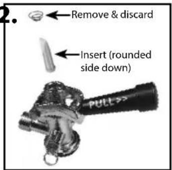
text_image
2. Remove & discard Insert (rounded side down)Remove the packing spring and Backflow Stopper from inside the Keg Coupler, then reinsert the Backflow Stopper into the Keg Coupler (rounded side down).

natural_image
Close-up of a mechanical valve component with a circular dial indicator (no text or symbols visible)Remove the black packing cap from the top of the Coupler, then place the Top Coupler Washer flush and centered on the top of the Keg Coupler.
3.

natural_image
Close-up of a mechanical tool with a handle and lever, showing a curved arrow indicating rotation (no text or symbols visible)After the Tap Tower has been placed on top the cabinet and the hose line feeds through the bottom, attach the wing nut to the Keg Coupler.
ATTACHING COUPLER TO REGULATOR
1.
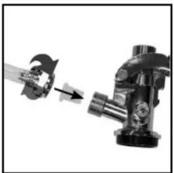
natural_image
Mechanical assembly diagram showing a rotating component being processed into a flanged housing (no text or symbols visible)If not already inserted, insert the CO_2 Directional Washer into the Keg Coupler. Then screw the CO_2 Line onto the Keg Coupler.
2.
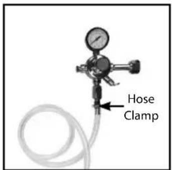
text_image
Hose ClampPush the other end of the CO2 Line through the hole in the rear of the cabinet. Slide a Hose Clamp onto the end of the CO2 Line, then attach the hose to the barb fitting on the bottom of the regulator. Secure the CO_2 Line by tightening the Hose Clamp with a flathead screwdriver.
ATTACHING REGULATOR TOCO2 TANK
IMPORTANT! When you purchase your first keg of beer, you must also have your CO₂ Tank filled by a local supplier. CO₂ Tanks can be filled at locations such as welding supply shops, party stores, and wherever kegs are purchased.
1.

text_image
Black-and-white photo of a mechanical device with visible warning sign and partial text on the leftAlign and hook the 4 holes of the CO₂ Tank Holder with the screws on the back of the unit.
2.
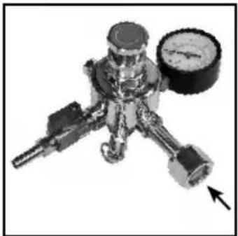
natural_image
Mechanical pressure regulator device with valve and gauge (no visible text or symbols)Make sure the white nylon High Pressure Washer (already installed) is attached to the Regulator.
3.

natural_image
Close-up of a gas cylinder with pressure gauge and valve, no visible text or symbolsUse an adjustable wrench (not included) to attach the Regulator to the CO_2 Tank.
4.

natural_image
Industrial oxygen cylinder with pressure gauge and tubing, no visible text or symbolsPlace the CO2 Tank into the CO2 Tank Holder.
COMPLETED CO2 TANK INSTALLATION
Below is an overview of how the interior and back panel of your KEGERATOR™ should look at this point of assembly.
Interior Cabinet Back Exterior
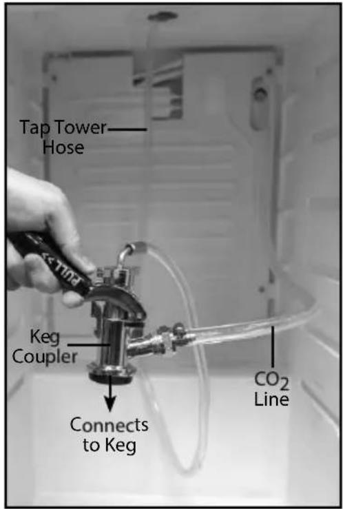
text_image
Tap Tower Hose Keg Coupler Connects to Keg CO2 Line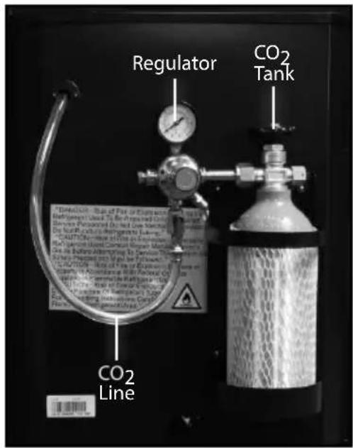
text_image
Regulator CO2 Tank CO2 Line
DANGER! CO2 can be dangerous! CO2 cylinders contain high-pressured gas, which can be hazardous if handled improperly. They must be handled with care.
TEMPERATURE GAUGE
The temperature gauge is located in the interior cabinet of the KEGERATOR™ in the upper left-hand corner.
NOTE: Before purchasing a beer keg, allow the unit to cool for 48 hours.

flowchart
graph LR
    A["1 2 3 4 5 6 7"] --> B["Warmer ColderNormal Use"]
    B --> C["..."]
    C --> D["..."]
    D --> E["..."]
    E --> F["..."]
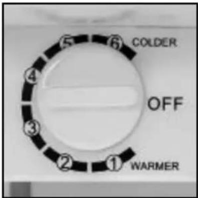
text_image
COLDER OFF WARMERINSTALLING THE GUARDRAIL / DRIP TRAY
- Place the Guardrail on top of the unit and align all pegs of the Guardrail with the holes on top of the unit.
- Secure the Guardrail to the unit by pushing the pegs inside the corresponding holes.
- Place the Drip Tray at the base of the Tap Tower.
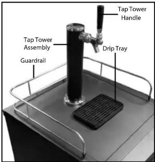
text_image
Tap Tower Handle Tap Tower Assembly Guardrail Drip TrayTAPPING THE BEER KEG
(SINGLE VALVE-TYPE KEG)
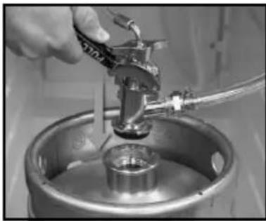
1.
natural_image
Close-up of a hand pouring liquid into a metal tank (no visible text or symbols)Make sure the black pull handle of the Coupler is in the open (up) position, then insert the Coupler into the locking neck of the beer keg.
3.
natural_image
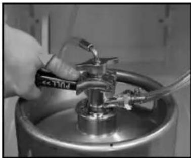
Close-up of a hand using a water dispenser to lift a stainless steel water dispenser into a container (no visible text or symbols)Make sure the Tap Tower is in the closed (handle pointing straight up) position. Secure the connection by pulling the Coupler handle out and pushing down until it locks into position. The pull handle will "click" when it shifts into the final downward position. This will open the beer and CO₂ gas valves. The Keg is now tapped.
2.
natural_image
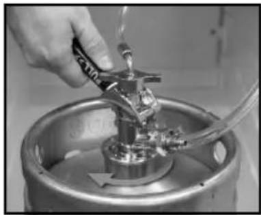
Close-up of a hand pouring liquid into a metallic cylindrical container with tubing (no visible text or symbols)Turn the Coupler clockwise until it locks securely into position.
SETTING THE REGULATOR
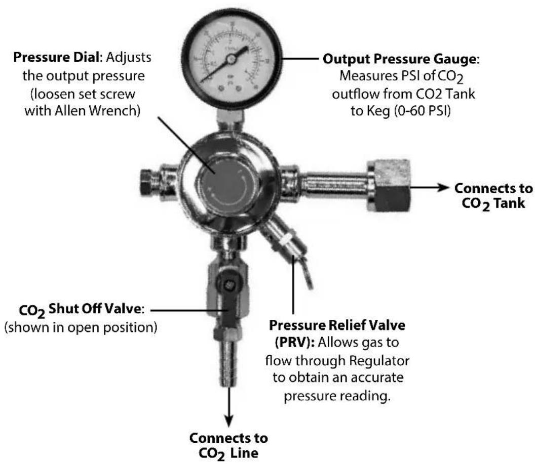
The Regulator connects the CO2 Tank to the CO2 Line, while measuring PSI (pounds per square inch) and the volume of CO_2 in the tank. Set the Output Pressure Gauge between 8-12 PSI for a nice, frothy head.
Overview
text_image
Pressure Dial: Adjusts the output pressure (loosen set screw with Allen Wrench) Output Pressure Gauge: Measures PSI of CO₂ outflow from CO2 Tank to Keg (0-60 PSI) Connects to CO₂ Tank CO₂ Shut Off Valve: (shown in open position) Pressure Relief Valve (PRV): Allows gas to flow through Regulator to obtain an accurate pressure reading. Connects to CO₂ LineHow To Set Regulator
1.

natural_image
Close-up of a gas regulator with pressure gauge and flanged cylinder, no visible text or symbolsClose the Shut Off Valve on the Regulator, and open the CO_2 Tank valve completely by turning it counterclockwise.
2.

natural_image
Industrial gas pressure regulator with conical tank and pressure gauge (no visible text or symbols)Slowly turn Pressure Dial all the way to the negative (-), then pull the Pressure Relief Valve (PRV) to ensure an accurate reading. Then very slowly turn the Pressure Dial clockwise until the desired pressure is shown on the Output Pressure Gauge (8-12 PSI is recommended).
» Turning clockwise will increase the output pressure (higher PSI).
» Turning counter-clockwise will decrease the output pressure (lower PSI).
3.

natural_image
Close-up of a gas regulator with pressure gauge and coiled tube (no visible text or symbols)Once desired pressure is reached, tighten the inner Locking Ring. Pull the PRV to assure the correct setting. If necessary, readjust your settings.
Next, open the CO₂ Shut Off Valve on the Regulator to allow gas to flow from the Regulator to the Keg Coupler. You will hear the keg pressurizing. The output needle will drop momentarily until the pressure has equalized. Then the needle will return to the point you set it at.
4.
Finally, we suggest you re-check the output pressure on the Regulator, and if necessary re-adjust starting at step #1 until the desired pressure is reached.
HOW TO OPERATE
Follow the steps below to dispense beer from your KEGERATOR ^™ .
- Make sure the unit is plugged into a properly grounded AC outlet.
- Place the Drip Tray under the beer faucet to avoid messes from excess beer.
- To dispense beer pull the Tap Handle towards you. Refer to the section on Tapping the Beer Keg if the beer does not dispense.
-
When pouring, hold the glass steady at a 45^ angle. When it is 23 full, straighten the glass. Ideally, foam should have a tight creamy head and the collar on an average glass should be 34 to 1" high.
-
Increase the pressure if the beer runs too slowly (see Setting the Regulator section). Generally, 8-10 PSI is recommended.
-
Cheers!
CONVERT TO REFRIGERATOR
Follow these steps to easily convert your KEGERATOR™ into a refrigerator.
-
Remove all parts and hoses from the interior and exterior of the unit, including all hoses, the CO2 Tank and Tap Tower.
-
To seal off the unit, insert the Top Cabinet Plug into the opening on the top of the cabinet.

natural_image
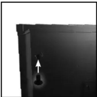
Black industrial vessel with a circular top and arrow pointing downward (no text or symbols visible)- Then insert the CO₂ Hole Plug into the CO₂ Line hole located in the upper left corner on the back exterior of the cabinet.
natural_image
Close-up of a black metal door with a white upward arrow pointing to a dark interior detail (no text or symbols visible)- Arrange the included Wire Racks in the cabinet interior to fit your refrigeration needs.
HELPFUL TIPS
- IMPORTANT! If the refrigerator has been placed in a horizontal or tilted position for any period of time wait 8 hours before plugging the unit in.
- It is recommended that you flush the hoses with water prior to first use to remove any dust and debris from shipping.
- Open the CO2 Tank with a 1/4 turn to start, then use the regulator to adjust to desired pour. If it is not enough, continue to open the CO2 Tank by a 1/4 turn and use regulator until desired setting is reached.
- It is normal to see condensation form on the faucet. It is caused by the difference in temperature between the cold beer and the inside of the faucet when beer is flowing through the line.
- Humidity can cause ice to build up inside the unit, so you will need to periodically defrost it. A hole in the back of the unit will allow water to drain out of the KEGERATOR™. NOTE: Do not use sharp objects to remove ice build up as this may damage the unit.
Foamy Beer
Follow these steps to prevent foamy beer:
- Confirm the packing spring in the Keg Coupler is removed and discarded. It is not to be placed inside the Keg Coupler when unit is assembled.
- Make sure there is only one Backflow Stopper inserted and it falls out easily if the Keg Coupler is flipped over. If you have to force it out with a screwdriver, it is getting lodged in the Keg Coupler. Try exchanging it with the included replacement.
- Confirm the beer lines are not kinked and are clean.
-
You may need to adjust down your pressure, even if it is below the recommended 8-12 PSI:
-
Before lowering the pressure, close the CO 2 Shut Off Valve (turn to 9 o'clock position) and use a 1.5 mm Allen Wrench to loosen the Allen Set Screw on the red +/- adjustment dial. This will restrict excess CO 2 from entering the keg.
- Adjust the pressure down to 8 PSI or below. Lock the red +/- dial back in place by tightening with the Allen Wrench.
- Pull the Release Valve on the Regulator to get an accurate reading of CO _2 pressure.
- With the Shut Off Valve still closed, move down to your Coupler.
- Pull the release valve on the Coupler to remove any excess CO that may have been pushed into the keg at another point.
-
Once most or all has released, open the Shut Off Valve (6 o'clock position) and attempt to pour a beer.
-
Keep in mind that jostling a keg can create foamy beer.
- Temperature also may affect the beer, so be sure it is not too warm or too cold. 37^ F is an ideal temperature.
- A faulty valve on the keg itself may cause the Keg Coupler to not seal well. Make sure all connections are secure and well tightened. Ensure all Washers are intact and correctly placed. Confirm the Directional Washer has a hole in it when pinched between the fingers.
CLEANING & MAINTENANCE
To prevent the buildup of yeast, mold and bacteria, it's recommended that you clean your KEGERATOR™ every time you switch a keg or every five weeks, whichever is shorter.
NEVER use an abrasive sponge, cloth or scouring pad on this appliance.
Clean Beer Lines
For best results, we recommend purchasing a beer line cleaning kit. There are several different methods for cleaning beer lines, including hand pump cleaning kits, pressurized cleaning kits, and recirculating cleaning pumps. Follow the directions included in each kit to clean your KEGERATOR™ beer lines.
Clean Tap Tower Spigot
As beer residue left behind on the Tap Tower Spigot evaporates, it leaves behind sticky sugars that can make the handle hard to pull. To avoid this, clean the Tap Tower Spigot after every use.
IMPORTANT! Be sure to untap your keg before removing the Tap Tower Spigot.
- Remove the Spigot Handle, then use the Tap Tower Wrench to remove the Tap Tower Spigot. Be sure to not lose the interior spring when removing the Tap Tower Spigot.
NOTE: The Tap Tower Spigot has a reverse thread and can be removed by turning clockwise.

natural_image
Close-up of a black and white water tap shaker with a handle, mounted on a metal stand (no visible text or symbols)- Wash the Spigot Handle, Tap Tower Spigot and interior spring in hot, soapy water. Allow parts to dry before reassembling.

text_image
Spigot Handle Spring Tap Tower SpigotWhen Unit Is Not In Use
Adjust the temperature dial to "Warmer", especially when in colder environments as this unit does not self-defrost and ice may build up inside the unit.
NOTE: To avoid permanent damage to the unit, never use sharp objects to remove built up ice inside the unit.
RETURNS & WARRANTY
SHOULD YOUR UNIT NOT WORK OR IF DAMAGED WHEN YOU FIRST TAKE IT OUT OF THE BOX, PLEASE RETURN IT TO THE PLACE OF PURCHASE IMMEDIATELY.
HOMECRAFT™ KEGERATOR™ / BK49BS
Should you have any questions, please contact us via email or at the customer service number listed below between the hours of 8:00 AM and 5:00 PM, Monday through Friday, Central Standard Time.
Distributed by:
Nostalgia Products LLC
1471 Partnership Dr.
Green Bay, WI 54304-5685
Customer Service
Phone: (920) 347-9122
Web: www.nostalgiaproducts.com
Customer Service Inquiry
To submit a Customer Service inquiry, go to www.nostalgiaproducts.com and fill out the Customer Service Inquiry form and click the Submit button.
A representative will contact you as soon as possible.
Product Warranty Terms
Nostalgia Products LLC (the "Company") hereby warrants that for a period of one (1) year from the date of original purchase, this product will be free of defects in material and workmanship under normal home use, provided that the product is operated and maintained in accordance with the operating instructions. As the sole and exclusive remedy under this warranty, the Company will at its discretion either repair or replace the product found to be defective, or issue a refund on the product during the warranty period. This warranty is only available to the original retail purchaser of the product from the date of initial retail purchase, and is only valid with the original sales receipt, as proof of purchase date is required to obtain warranty benefits. All warranty claims must be brought to the attention of the Company within the warranty period and no later than 30 days of the failure to perform. This warranty does not cover normal wear or damage caused by shipping, mishandling, misuse, accident, alteration, improper replacement parts, or other than ordinary household use. You may be required to return the product (with shipping prepaid by you) for inspection and evaluation. Return shipping costs are not refundable. The Company is not responsible for returns damaged or lost in transit. Unless otherwise specifically permitted by the operating instructions, this warranty applies to indoor household use only. In order to obtain service under this warranty, please contact the Company at the telephone number listed above or by filling out the Customer Service Inquiry Form located at www.nostalgiaproducts.com. Warranty valid only in USA and Canada.
This warranty is in lieu of all other warranties, expressed or implied, including warranties of merchantability and fitness for a particular purpose, which are hereby excluded to the extent permitted by law. In no event shall the Company be liable for any indirect, incidental, consequential, or special damages arising out of or in connection with this product or the use thereof. Some states, provinces or jurisdictions do not permit the exclusion or limitation of incidental or consequential damages, so the foregoing exclusion or limitation may not apply to you.
This warranty does not apply to re-manufactured merchandise.
Please read the operating instructions carefully. Failure to comply with the operating instructions will void this warranty.
For more information, visit us online at www.nostalgiaproducts.com.
Like us on Facebook at www.facebook.com/NostalgiaElectrics.
Follow our boards on Pinterest at www.pinterest.com/nostalgiaelctrx.
Tweet along with us on Twitter at www.twitter.com/NostalgiaElctrx.
TABLE DES MATIÈRES
SÉCURITÉ 20
PRÉCAUTIONS IMPORTANTES 21
PRÉCAUTIONS IMPORTANTES ADDITIONNEL 21
INTRODUCTION.... 23
PIÈCES 24
INSTALLATION DES ROULETTES 26
APERÇU DE L'ASSEMBLAGE....26
natural_image
Close-up of a black rubber ring (no text or symbols visible)text_image
Exploded view diagram of automotive components with numbered labels for identificationnatural_image
Close-up of a metallic mechanical component with a circular wheel and bolts, shown against a dark background (no text or symbols visible)natural_image
Two views of a mechanical casket being processed, showing before and after motion (no text or symbols)text_image
Tap Tower Tap Tower Washernatural_image
Black and white photo of a tall water tap with a handle and arrow indicating rotation (no text or symbols)natural_image
Close-up of a mechanical valve component with a circular dial indicator (no text or symbols visible)natural_image
Close-up of a mechanical tool with a curved arrow indicating rotation (no text or symbols visible)natural_image
Mechanical assembly diagram showing a valve being inserted into a housing (no text or symbols visible)text_image
Black-and-white photo of a mechanical device with warning label and warning text in Chinesenatural_image
Mechanical valve assembly with pressure gauge and directional arrow (no text or symbols)natural_image
Close-up of a gas cylinder with pressure gauge and valve (no visible text or symbols)natural_image
Medical oxygen cylinder and pressure gauge setup with warning label (no readable text or symbols)natural_image
Close-up of a hand using a tool to lift a metallic cylindrical component into a metal barrel (no visible text or symbols)natural_image
Close-up of a hand pouring liquid into a metallic cylindrical container with a handle (no visible text or symbols)natural_image
Close-up of a hand using a water dispenser to lift a metallic cylindrical container (no visible text or symbols)natural_image
Close-up of a gas regulator with pressure gauge and conical flask, no visible text or symbolsnatural_image
Industrial gas pressure regulator with conical flask and pressure gauge (no visible text or symbols)natural_image
Close-up of a gas regulator with pressure gauge and coiled tube (no visible text or symbols)natural_image
Top-down view of a black industrial vessel with a circular top and arrow pointing to a central hole (no text or symbols visible)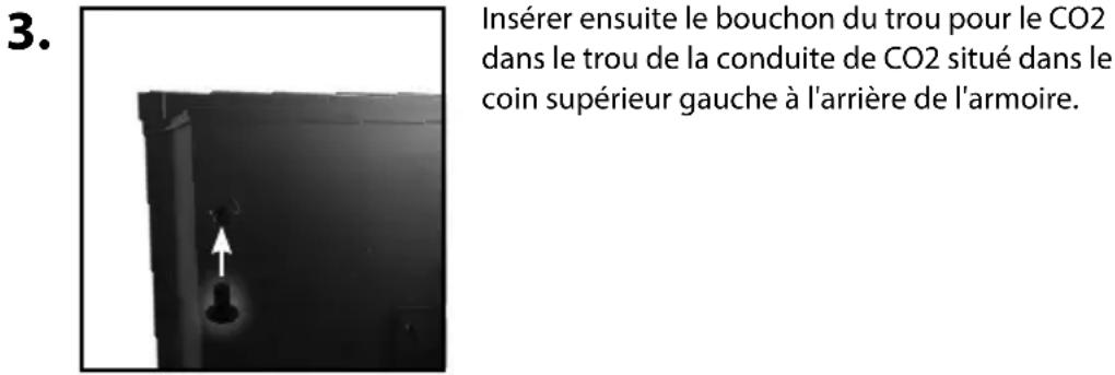
natural_image
Black and white photo of a water tap in a kitchen setting (no text or symbols visible)Nostalgia Products LLC
1471 Partnership Dr.
Green Bay, WI 54304-5685
natural_image
Close-up of a black rubber ring (no text or symbols visible)text_image
Exploded view diagram of automotive components with numbered labels for identificationnatural_image
Close-up of a metallic mechanical component with a circular wheel and bolts, no visible text or symbols.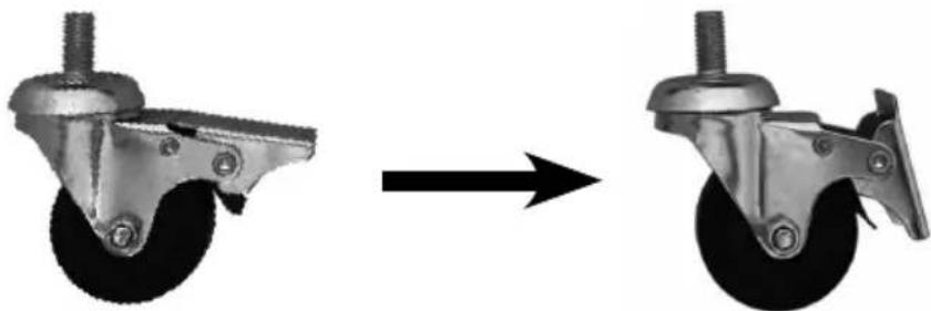
natural_image
Two views of a mechanical casket being processed, showing before and after states (no text or symbols)natural_image
Black and white photo of a tall water tap with a handle and arrow indicating rotation (no text or symbols)natural_image
Close-up of a metallic mechanical valve component with a circular top and arrow pointing to it (no text or symbols visible)natural_image
Close-up of a mechanical tool with a handle and lever mechanism, no visible text or symbolsnatural_image
Mechanical assembly diagram showing a valve being rotated and then displaced (no text or symbols present)text_image
Hose Clampnatural_image
Close-up of a mechanical device with a warning symbol and textured background (no readable text or symbols)natural_image
Mechanical pressure regulator device with valve and gauge (no visible text or symbols)natural_image
Close-up of a gas cylinder with pressure gauge and valve, no visible text or symbolsnatural_image
Laboratory oxygen cylinder with pressure gauge and tubing, no visible text or symbolsnatural_image
Close-up of a hand pouring liquid into a metal tank (no visible text or symbols)natural_image
Close-up of a hand pouring liquid into a metallic cylindrical container with a valve (no visible text or symbols)natural_image
Close-up of a hand using a water dispenser to clean a stainless steel container (no visible text or symbols)natural_image
Close-up of a gas regulator with pressure gauge and cylindrical tank (no visible text or symbols)natural_image
Industrial gas cylinder and pressure gauge mounted on a cylindrical tank (no visible text or symbols)natural_image
Close-up of a gas regulator with pressure gauge and coiled tube (no visible text or symbols)natural_image
Black industrial tank with a circular top and arrow pointing downward (no text or symbols visible)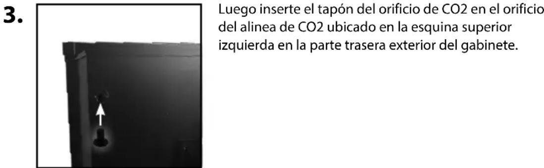
natural_image
Interior view of a closed refrigerator with open doors showing shelves and ventilation (no text or symbols visible)CONSEJOS ÚTILES
natural_image
Black and white photo of a water tap in a kitchen setting (no text or symbols visible)Nostalgia Products LLC
1471 Partnership Dr.
Green Bay, WI 54304-5685
Servicio al cliente