Pro Chem - Electronic measuring device HAYWARD - Free user manual and instructions
Find the device manual for free Pro Chem HAYWARD in PDF.

User questions about Pro Chem HAYWARD
0 question about this device. Answer the ones you know or ask your own.
Ask a new question about this device
Download the instructions for your Electronic measuring device in PDF format for free! Find your manual Pro Chem - HAYWARD and take your electronic device back in hand. On this page are published all the documents necessary for the use of your device. Pro Chem by HAYWARD.
USER MANUAL Pro Chem HAYWARD
natural_image
Abstract geometric logo with stylized letter H inside a circular frame (no text or symbols)HAYWARD®
text_image
HUAWARD 7.40°C 780°C HUAWARD 7.40°C 1.25°C 780°CCE EAC UK CA

natural_image
Two line icons: one open with an information symbol, the other closed with an open book (no text or symbols present)OWNER'S MANUAL

natural_image
Abstract geometric logo with stylized letter H inside a circular frame (no text or symbols)HAYWARD®

text_image
NEWABLED 7.40°C 780°C Pro Chen NEWABLED 7.40°C 1.25°C 780°C Pro ChenCE EAC UK CA

natural_image
Two line icons: one open with an information symbol, the other closed with an open book (no text or symbols present)PLEASE KEEP THIS MANUAL FOR FUTURE REFERENCE
⚠ WARNING – Carefully read the instructions that appear in this manual and on the device. Failure to comply with the instructions can cause injuries. This document must be given to every pool user, who should keep it in a safe place.
⚠ WARNING – Disconnect the equipment from the mains supply before any intervention.
⚠ WARNING – All electrical connections must be carried out by a qualified approved electrician in accordance with the standards currently in force in the country of installation or, failing this, in accordance with the international standard IEC 60334-7-702.
| F NF C 15-100 GB BS7671:1992 | |||
| D DIN VDE 0100-702 EW SIST HD 384-7-702.S2 | |||
| A ÖVE 8001-4-702 H MSZ 2364-702:1994 / MSZ 10-533 1/1990 | |||
| E UNE 20460-7-702 1993, REBT ITC-BT-31 2002 M MSA HD 384-7-702.S2 | |||
| IRL IS HD 384-7-702 PL TS IEC 60364-7-702 | |||
| I CEI 64-8/7 CZ CSN 33 2000 7-702 | |||
| LUX 384-7.702 S2 | SK STN 33 2000-7-702 | ||
| NL NEN 1010-7-702 | SLO SIST HD 384-7-702.S2 | ||
| P RSIUEE | TR TS IEC 60364-7-702 | ||
⚠ WARNING – Check that the device is plugged into a power outlet that is protected against short-circuits. The device must also be powered via an isolating transformer or a residual current device (RCD) with a nominal operating residual current not exceeding 30 mA.
⚠ WARNING – Ensure that children cannot play with the device. Keep your hands and any foreign object away from openings and moving parts.
⚠ WARNING – Check that the supply voltage required by the product corresponds to the voltage of the distribution network and that the power supply cables are suitable for the product power supply.
⚠ WARNING – Chemicals can cause internal and external burns. To avoid death, serious injury and/or damage to equipment, wear personal protective equipment (gloves, goggles, mask, etc.) when servicing or maintaining this device. This device must be installed in an adequately ventilated place.
⚠ WARNING – The unit shall not be operated when there is no water flow in the cell.
⚠ WARNING – To reduce the risk of electric shock, do not use an extension cable to connect the device to the mains. Use a wall socket.
⚠ WARNING – Use, cleaning or maintenance of the device by children over 8 years of age or by people with impaired physical, sensory or mental capacities, or a lack of experience or expertise, should only take place once they have received appropriate instruction and under adequate supervision of an adult who is responsible for them, to ensure the device is handled safely and avoid all risk of danger.
⚠ WARNING – Use only original Hayward® parts.
⚠ WARNING – If the power supply cable is damaged, it must be replaced by the manufacturer, the after-sales service or similarly qualified persons to avoid danger.
⚠ WARNING – The device must not be used if the power cord is damaged. An electric shock could occur. A damaged power cord must be replaced by the after-sales service or similarly qualified persons to avoid danger.
INDEX
- General
- Pack contents
- Installation
3a. View of overall installation
3b. Wall-mounted installation
3c. Installation of pH and ORP probes, and acid dosing pump
3d. Installation of amperomteric chlorine probe
3e. Installation of membrane chlorine probe
- Electrical connections
4a. Electrical installation and wiring
4b. Electrical suppressor device
4c. Trigger input by circulation pump
-
Specifications
-
Setup and Operation
6a. Description of the home screen and defaults parameters
6b. View level, three and two parameters
6c. Main menu
6d. pH probe calibration
6e. ORP probe calibration
6f. Chlorine calibration
6g. Temperature probe calibration
6h. Flow Rate Sensor Calibration
- Web connection setup
- Dosing method
- Alarms
- Servicing
- Troubleshooting guide
- Environmental information
1. GENERAL
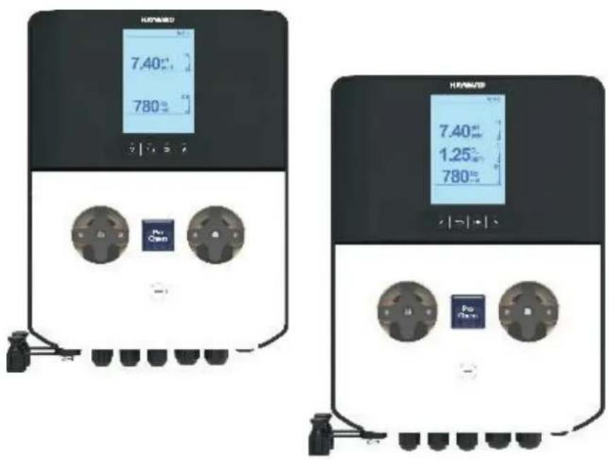
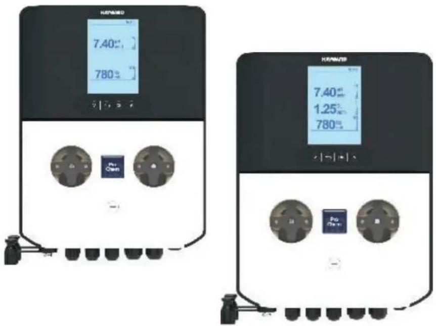
ProChem Double device is an automatic dosing system to disinfect your swimming pool water with liquid injection. Information displayed: readings of pH, ORP and Free Chlorine, state of liquid injection and alarms. Before carrying out ANY work inside control panel of the ProChem Double device, make sure you disconnect it from the power supply. Failure to comply with the instructions contained in this manual could cause injury to people and/or damage to the appliance and the system.
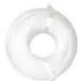
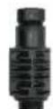
2. PACK CONTENTS
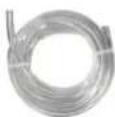
A: PVC Crystal 4x6 suction hose (4 m)
B: Polyethylene delivery hose (5 m)
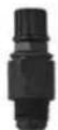
C: FPM Lip valve (3/8" GAS)
F: Reducer for injection valve (1/2" M to 3/8" F)
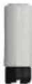
G: Foot filter (PP riser)
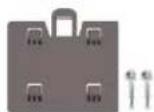
H: Mounting bracket kit (ø=6 mm screws)
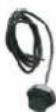
I: Temperature sensor
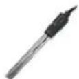
L: pH probe
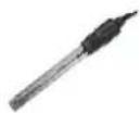
M: ORP probe
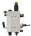
N: Probes holder with Chlorine probe included
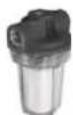
O: Filter Minor (5")
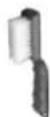
P: Cleaning brush chlorine probe
Q: Pyrex Balls for chlorine probe
R: pH 4 Buffer solution
S: pH 7 Buffer solution
T: 465 mv Calibration solution
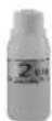
U: Water

V: EMI Coil
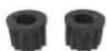
W: Nuts for peristaltic tube
X: Probes holder with Chlorine probe included
| Item*\System | PROChem Double pH/ORP (PRO-CHEM-DPHRXG) | PROChem Double pH/ORP/CL-AMP (PRO-CHEM-DPHCL) | PROChem Double pH/ORP/CL-POT (PRO-CHEM-DPHCL2) |
| A | 2 | 2 | 2 |
| B | 2 | 2 | 2 |
| C | 2 | 2 | 2 |
| D | 2 | 1 | 1 |
| E | 5 | 5 | 5 |
| F | 2 | 2 | 2 |
| G | 2 | 2 | 2 |
| H | 1 | 1 | 1 |
| I | 1 | 1 | 1 |
| L | 1 | 1 | 1 |
| M | 1 | 1 | 1 |
| N --- 1 --- | |||
| O --- 1 1 | |||
| P --- 1 --- | |||
| Q --- 1 --- | |||
| R | 1 | 1 | 1 |
| S | 1 | 1 | 1 |
| T | 1 | 1 | 1 |
| U | 1 | 1 | 1 |
| V | 1 | 1 | 1 |
| W | 2 | 2 | 2 |
| X | --- | --- 1 |
*NOTE: The values from the table represent the number of items inside the package.
3. INSTALLATION
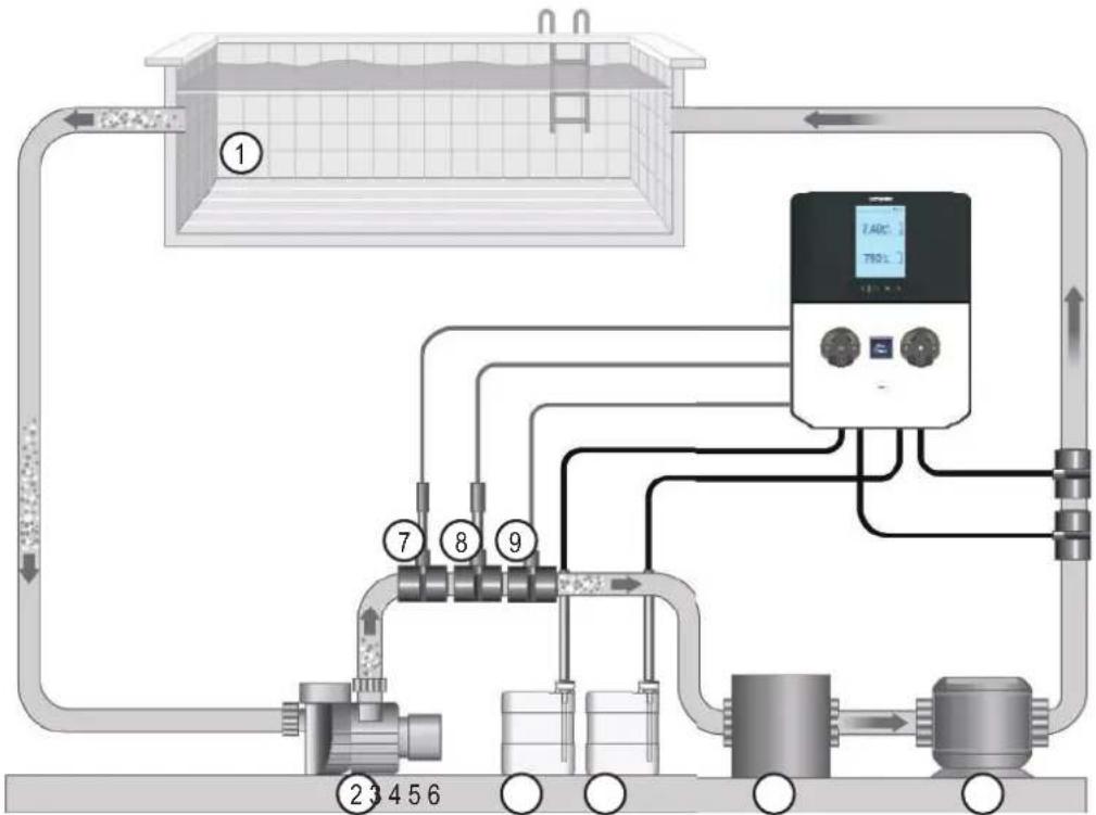
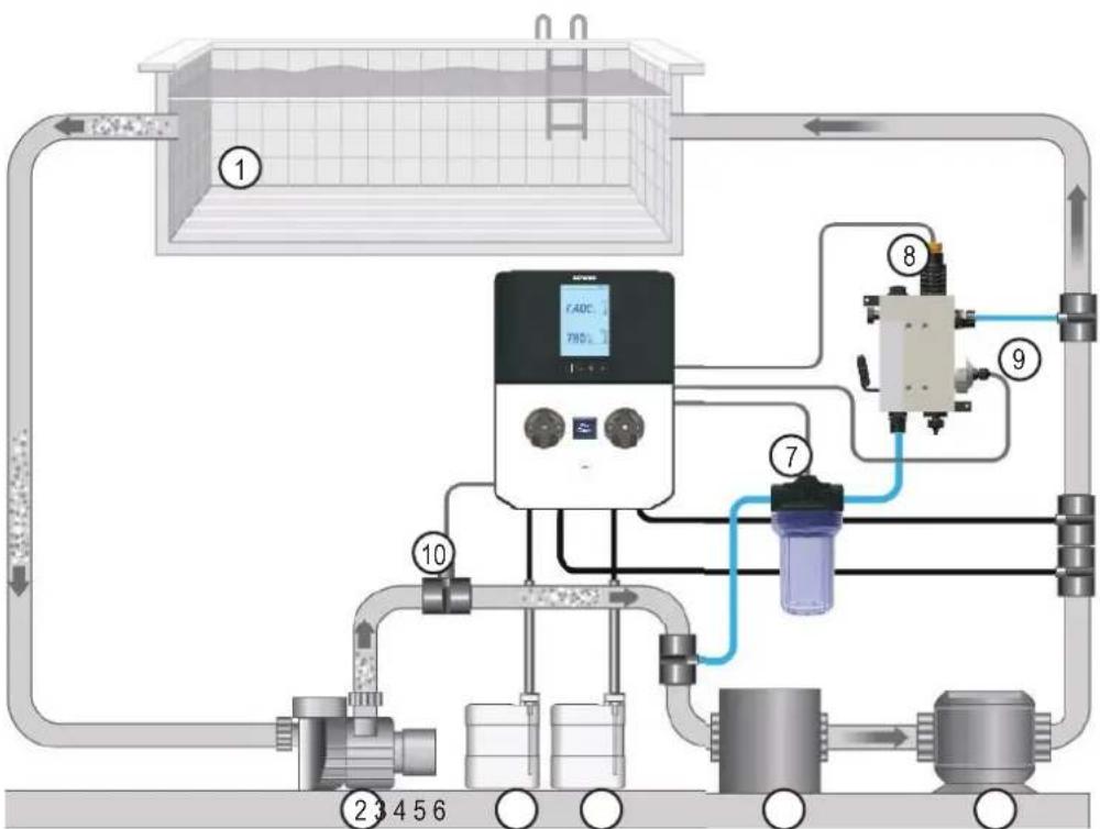
3a. View of overall installation
flowchart
graph TD
    A["Input"] --> B["Reactor Unit ①"]
    B --> C["Processing Unit ⑦"]
    C --> D["Reactor Unit ⑧"]
    D --> E["Reactor Unit ⑨"]
    E --> F["Digital Monitoring System"]
    F --> G["Output"]
    style A fill:#f9f,stroke:#333
    style B fill:#ccf,stroke:#333
    style C fill:#cfc,stroke:#333
    style D fill:#fcc,stroke:#333
    style E fill:#cff,stroke:#333
    style F fill:#ffc,stroke:#333
    style G fill:#cfc,stroke:#333
PRO-CHEM-DPHRXG · ProChem Double pH / ORP installation layout
- Pool
- Circulation pump
- Acid
- Chlorine
- Filter
- Heat exchanger
- pH probe
- ORP probe
- Temperature sensor
flowchart
graph TD
    A["①"] --> B["②"]
    B --> C["③"]
    C --> D["④"]
    D --> E["⑤"]
    E --> F["⑥"]
    F --> G["⑦"]
    G --> H["⑧"]
    H --> I["⑨"]
    I --> J["⑩"]
    J --> K["⑪"]
    K --> L["⑫"]
    L --> M["⑬"]
    M --> N["⑭"]
    N --> O["⑮"]
    O --> P["⑯"]
    P --> Q["⑰"]
    Q --> R["⑱"]
    R --> S["⑲"]
    S --> T["⑳"]
    T --> U["㉑"]
    U --> V["㉒"]
    V --> W["㉓"]
    W --> X["㉔"]
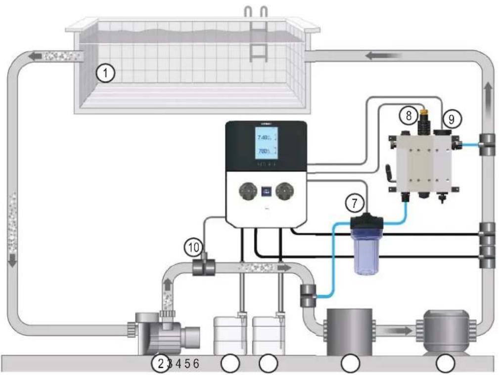
PRO-CHEM-DPHCL · ProChem Double pH / ORP / CL-Amperometric installation layout
- Pool
- Circulation pump
- Acid
- Chlorine
- Filter
- Heat exchanger
- ORP probe
- pH probe
- CI-Amp probe
- Temperature sensor
flowchart
graph TD
    A["①"] --> B["②"]
    B --> C["③"]
    C --> D["④"]
    D --> E["⑤"]
    E --> F["⑥"]
    F --> G["⑦"]
    G --> H["⑧"]
    H --> I["⑨"]
    I --> J["⑩"]
    J --> K["⑪"]
    K --> L["⑫"]
    L --> M["⑬"]
    M --> N["⑭"]
    N --> O["⑮"]
    O --> P["⑯"]
    P --> Q["⑰"]
    Q --> R["⑱"]
    R --> S["⑲"]
    S --> T["⑳"]
    T --> U["㉑"]
    U --> V["㉒"]
    V --> W["㉓"]
    W --> X["㉔"]
- Pool
- Circulation pump
- Acid
- Chlorine
- Filter
- Heat exchanger
- ORP probe
- pH probe
- CI-Mem probe
- Temperature sensor
PRO-CHEM-DPHCL2 · ProChem Double pH / ORP / CL-Membrane installation layout
Warning!
Use with salt chlorinator:
For the pH systems, to prevent the risk of system malfunctioning or damage, observe the following instructions:
- Position the pH measuring probe prior to the chlorinator cell.
- To eliminate eddy currents, connect the pool water to an electrical ground point
- Position the product injection point after the chlorinator cell.
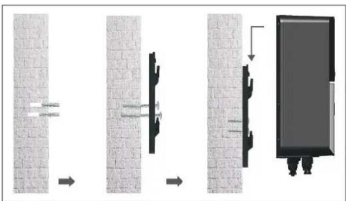
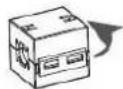
3b. Wall-mounted installation
Mount the control box on the wall. The box must be installed in the equipment room (dry, temperate, ventilated). Caution, acid vapours can cause irreversible damage to your device. Position the treatment product tanks accordingly.
Unplug the pool filter pump before you begin the installation. The installation must be performed in compliance with the regulations in effect in the country of installation.
natural_image
Diagram showing a mechanical assembly or mounting process with four sequential steps, no text or symbols present.
text_image
Warning! 2mMake sure that the injection pressure is below 1.5 bar
3c. Installation of pH and ORP probes, and acid dosing pump
The pH and ORP probes are «wet» packed and protected by a plastic cap. The probes must always remain wet. If the probes are allowed to dry, they will be permanently unusable (not covered by the warranty) and the pH-ORP test kit will be ineffective.
Remove the pH and ORP probes from their plastic protective caps and set the caps aside for later use (wintering). Insert the probes into the double probe holder and tighten to ensure they are watertight. Connect the probe holder to the valves screwed onto the saddle clamps and tighten by hand only. Check that the probes are watertight at startup. Seal with Teflon, if required.
After installation, check that the probes are constantly in contact with the water in the pool. When the filtration pump is not running (even for long periods), the water remaining in the chamber may be sufficient to protect the probes.
pH / ORP Probe positioning
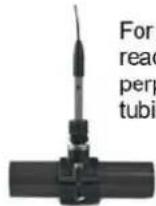
For optimum probe reading, position it perpendicular to the tubing.


text_image
The probe's angle of inclination must never exceed 45° from vertical.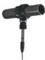

3d. Installation of amperomteric chlorine probe
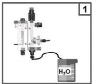
- Regulate the flow to 60L/h
- Open the spillage knob until the water came out, then close it
- Check the chlorine chamber for air bubbles, if there are present remove them using the flow regulator
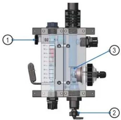
text_image
Technical diagram of a mechanical device with labeled parts, including pressure gauge and adjustment knobsVery important
After installing the probe in the plexi probe holder, wait at least 3 hours before the calibration procedure, in order to allow the sensor to polarize.
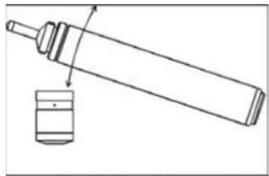
3e. Installation of membrane chlorine probe
- Fill to the brim the membrane cap with the provided electrolite

natural_image
Stacked cylindrical electronic devices with a pipette tip, no visible text or symbols-
Remove eventual air bubble in the membrane cap by gently tapping the cap using the body of the sensor
-
Clean the electrode using the provided abrasive paper. Note: the electrode must be a little inclined on the abrasive paper and not perfectly vertical, in order not ot remove the brown film that is on the extremity.
-
Assemble the sensor by inserting the body in the membrane cap and screwing it clockwise until it is correctly inserted. Excessive electrolite will overflow from the valve positioned where the red arrow is, you can clean by using simple water.
-
Move the second silicone gasket on top of the first one.
-
Insert the terminal cap onto the cable through the PG7 connector and fix the cable wir into the terminals. The recommended cable is: 4mm diameter, 2x 0.25 mm² wires.
natural_image
Technical line drawing of a mechanical component with a cylindrical base and a cylindrical shaft, showing no text or symbols.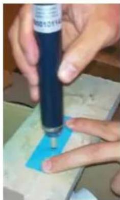
natural_image
Close-up of hands using a blue pen on a small object, no visible text or symbols
natural_image
Close-up of a mechanical component with a red arrow pointing to a cylindrical part (no visible text or symbols)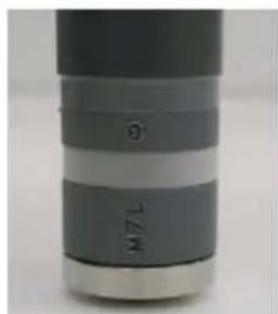
natural_image
Close-up of a cylindrical mechanical component with no visible text or symbols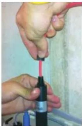
natural_image
Close-up of hands using a red tool to apply a black bottle (no visible text or symbols)
natural_image
Close-up of hands using a screwdriver to apply material to a black cylindrical component (no visible text or symbols)
HAYWARD®
-
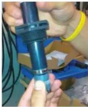
Screw the terminal cap clockwise until it is corectly fixed on the body of the sensor.
-
Insert the sensor in the tightening nut of the probe holder and then in the plexi probe holder.
natural_image
Close-up of hands assembling a blue mechanical component (no visible text or symbols)
natural_image
Close-up of hands using a red tool to apply liquid onto a black bottle (no visible text or symbols)Very important
After installing the probe in the plexi probe holder, wait at least 3 hours before the calibration procedure, in order to allow the sensor to polarize.
4. ELECTRICAL CONNECTIONS
4a. Electrical installation and wiring
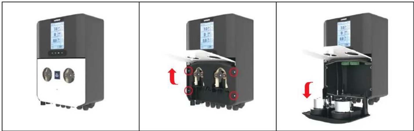
Connect the ProChem Double to a permanent power outlet.
Open the peristaltic pump lid (1), unscrew four screws (2) and pull the peristaltic pump on the side (3), as illustrated in the pictures below:
text_image
Three-panel diagram showing a device with digital display, internal components, and a close-up of the interior with red arrows indicating motion or change.Label connection:
ProChem Double pH + ORP connections label of PRO-CHEM-DPHRXG
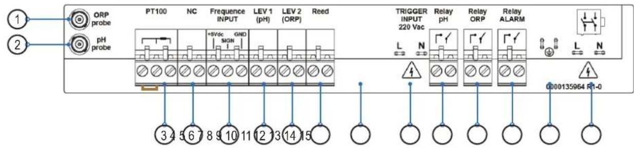
text_image
1 2 ORP probe pH probe PT100 NC Frequency INPUT LEV 1 (pH) LEV 2 (ORP) Reed +5Vdc GND SIGN 3 4 5 6 7 8 9 10 11 12 13 14 15 TRIGGER INPUT 220 Vac Relay pH Relay ORP Relay ALARM L N 0000135964 R1-0ProChem Double pH + ORP + CL-Amperometric connections label of PRO-CHEM-DPHCL
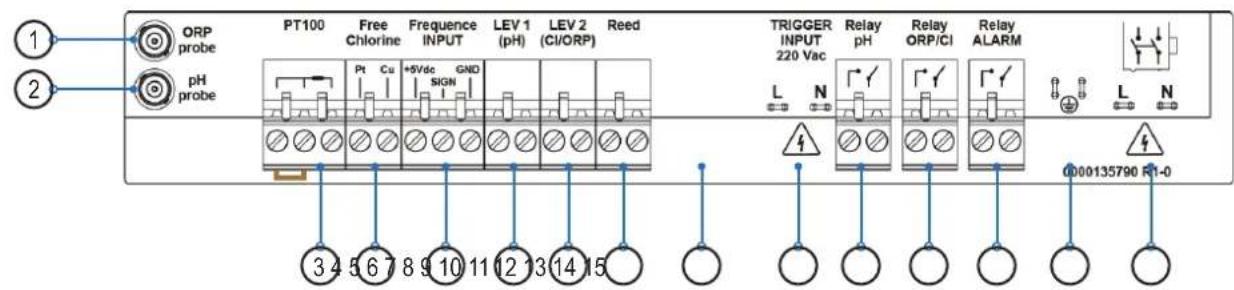
text_image
ORP probe pH probe PT100 Free Chlorine Frequency INPUT LEV 1 LEV 2 Reed Pt Cu +5Vdc GND SIGN (CI/ORP) 3 4 5 6 7 8 9 10 11 12 13 14 15 TRIGGER INPUT 220 Vac Relay pH Relay ORP/CI Relay ALARM L N 0000135790 R1-0ProChem Double pH + ORP + CL-Membrane connections label of PRO-CHEM-DPHCL2
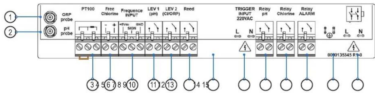
text_image
PT100 Free Frequency LEV 1 LEV 2 Reed ORP Free Freqence LEV 1 LEV 2 Reed probe Chlorine INPUT (pH) (CI/ORP) PH Probe +5Vac GND SIGN 345678910 111213 1415 TRIGGER Relay Relay INPUT 220VAC Relay Chlorine Relay ALARM L N 0000135345 R-0| Clamp | Connection description | ProChem Double Wire connection details Status | ||
| 1 ORP Input ORP Yellow BNC Probe ORP Probe Mandatory to connect | ||||
| 2 pH Input pH Blue BNC Probe pH Probe Mandatory to connect | ||||
| 3 Input Probe | TEMPERATURE SENSOR (PT100)A= two wires sensor, probe included in the packageB= three wires sensor, please check the optional colors probe | 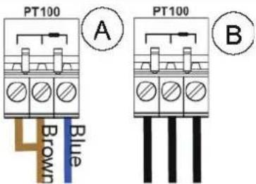 | Mandatory to connect | |
| 4 | Input Free Chlorine sensor | Input free chlorine probe*PRO-CHEM-DPHCLA = amperometric ( A signal probe)Pt: Platinum sensor (-)Cu: Cupper sensor (+)PRO-CHEM-DPHCL2B = potentiostatic (4-20mA probe)* Pay attention to the polarity | 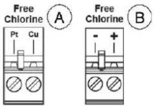 | Mandatory to connect |
| 5 | Frequency input by water meter pulse sender | Flow Rate (Freq. Input)A= Mechanical reedB= Padwheel hall sensor | 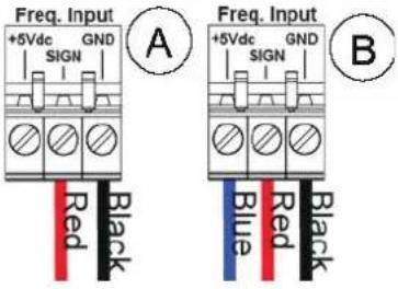 | Optional for pH / ORPMandatory for pH / ORP / FCI |
| 6 | Level (product tank) | pH Level probe Level probe for chemical tank Optional | ||
| 7 | Level (product tank) | Chlorine (ORP) level probe Level probe for chemical tank Optional | ||
| 8 | Flow Check input | Flow Check by REED sensor | 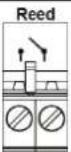 | Mandatory to connect |
| 9 Serial Port | None | 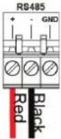 | None | |
| 10 | Trigger Input | Circulation Pump (220Vac input) | Please read paragraph 4c | Mandatory to connect |
| 11 | Output Relay | RL1 AUX1 pH | Dry contact | Optional |
| 12 | Output Relay | RL2 AUX2 OPR/Chlorine | Dry contact | Optional |
| 13 | Output Relay | RL3 Alarm | Dry contact | Optional |
| 14 | Earth connector | Earth | --- | Mandatory to connect |
| 15 | Power Supply | 220-240 Vac 50-60 Hz (F/N) | --- | Mandatory to connect |
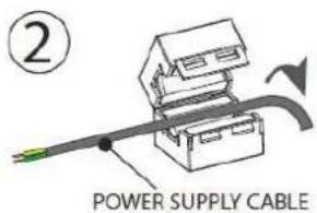
4b. Electrical suppressor device
It is mandatory to install the coil suppressor, please see the instructions below:
1
text_image
② POWER SUPPLY CABLE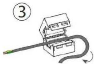
natural_image
Diagram of a mechanical device with a curved cable and labeled number 3 (no text or symbols on the diagram itself)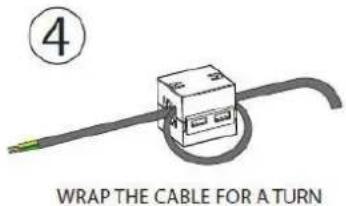
text_image
④ WRAP THE CABLE FOR A TURN4c. Trigger input by circulation pump
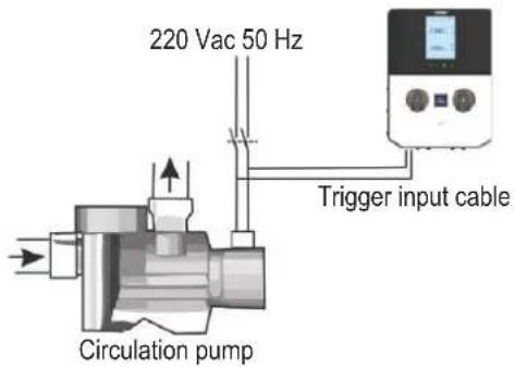
text_image
220 Vac 50 Hz Trigger input cable Circulation pumpConnect the Trigger cable as the example on the site with the traditional circulation pump, to check the flow is present in the pipe line.
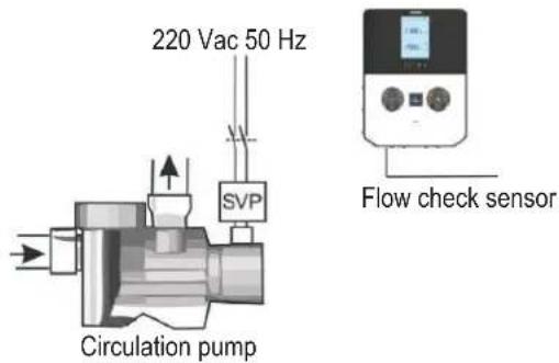
text_image
220 Vac 50 Hz SVP Circulation pump Flow check sensorDo not use the Trigger cable to the circulation pump if the SVP (speed variable pump) is present, but use the Flow check sensor, pay attention to disable or enable the function in the setting menu.
5. SPECIFICATIONS
| Specifications | ProChem Double pH/ORP PRO-CHEM-DPHRXG | ProChem Double pH/ORP/Chlorine PRO-CHEM-DPHCL / PRO-CHEM-DPHCL2 |
| Pump state Pause – Supply | Pause – Supply | |
| Probe calibration Automatic | Automatic | |
| Power supply 220-240 VAC | 50-60 Hz 220-240 VAC 50-60 Hz | |
| Consumption (W) 28 Watt 28Watt | ||
| Device precision ± 0.1 pH; ±10mV; ±1°C ± 0.1 pH; ±10mV; 0.1 ppm; ±1°C | ||
| Accuracy ±0.02pH, ±3mV; ±0.5°C ±0,02pH, ±3mV; 0,05 ppm; ±0,5°C | ||
| Range | 0-14pH; -99 -1000mV; 0...+55°C | 0-14pH; -99 -1000mV; 0-5 ppm; 0...+55°C |
| Flow rate pump (l/h) | 1.5 l/h | 4 l/h |
| Max. back-pressure | 1.5 bar | 1.5 bar |
| Relay contact (number 3) | 250 Vac 10A (resistive load) 250 Vac 10A (resistive load) | |
| Fuse | 500 mA (timed) | 500 mA (timed) |
| Weight | 2.5 Kg | 2.5 Kg |
| Dimensions (W–H–D) | 212 x 303 x 113 mm | 212 x 303 x 113 mm |
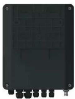
natural_image
Front view of a black electronic device casing with mounting holes and internal circuitry (no visible text or symbols)
natural_image
Simple black rectangular object with two small protrusions at the bottom (no text or symbols)
text_image
7.40°C 1.25°C 780°C App -
natural_image
Pure electrical circuit lines without any symbols6. SETUP AND OPERATION
The device is designed to be connected to a protected outlet at all times. The ProChem Double must not be disconnected unless the pool equipment is undergoing maintenance or the pool is to be closed (wintering).
Assuming that the chemical balance of the water is within the recommended ranges, the device can be started up.
6a. Description of the home screen and defaults parameters
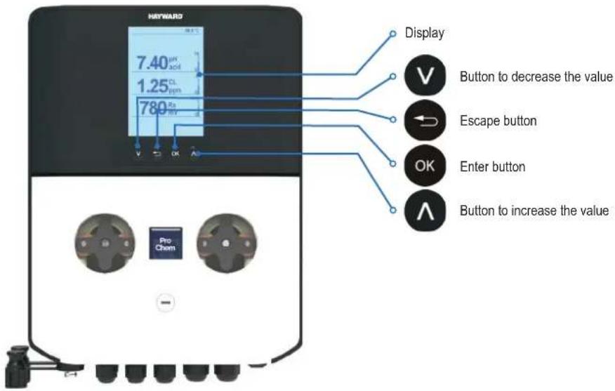
text_image
HYWARD 7.40μH acid 1.25 CL ppm 780 V OK A Display Button to decrease the value Escape button OK Enter button Button to increase the value Pro ChemDefault parameters
| n Item Value | ||||
| 1 Language EN | ||||
| 2 Set Point value 7.4 pH 700 mV 1.2 ppm | ||||
| 3 Dosing method Acid (pH) Low (ORP) | Low (Chlorine) | |||
| 4 OFA Time OFF | ||||
| 5 Calibration Full | ||||
| 6 Flow Input (Reed Sensor) | NO (normally open) (pH & ORP only) | NC (normally closed) (Chlorine) | ||
| 7 Circulation pump | ON (Enable) | |||
| 8 Dosing type | PROP; Relay Aux1, Aux2, Aux3 are disabled | |||
| 9 Power ON Delay | OFF | |||
| 10 | Flow Delay | OFF | ||
Measure alarm ranges default parameters
| n Item | Limits |
| 1 Temp. Measure min | + 10°C |
| 2 Temp. Measure Max | + 38°C |
| 3 pH Measure min | 6 pH |
| 4 pH Measure Max | 8.0 pH |
| 5 CRP Measure min | +450 mV |
| 6 CRP Measure Max | +850 mV |
| 7 Cl Measure min | 0.5 ppm |
| 8 Cl Measure Max | 2 ppm |
Init. Default. Menu
Press + V and switch on the device.
Set reset routine;
- Init. Default: restore default parameters device only
- Init. WiFi Module: restore default parameters WiFi module only
- Init. Calib. HW: restore raw HW calibration parameters.
Note: please make the probes calibration before using the system
Init. Default
▶ Init. Default
□ Init. WiFi Module
□ Init. Calib. HW
6b. View level, three and two parameters
Two parameters (pH + ORP) family and technician view
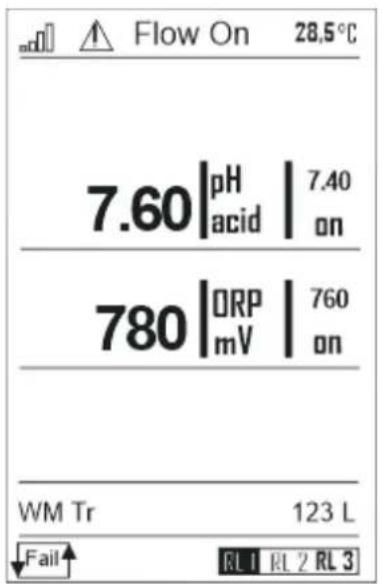
text_image
Flow On 28.5°C 7.60 |pH | 7.40 acid | on 780 |ORP | 760 mV | on WM Tr 123 L Fail RL1 RL2 RL3Three parameters (pH + ORP + Chlorine) family and technician view
Note: during the first installation please check the following steps:
a. Connect all probes
b. Calibrate the probes by wizard calibration routine
c. Check the device in running
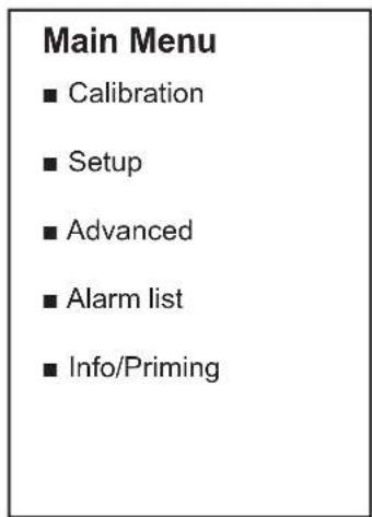
6c. Main menu

and select the of the following functions:

text_image
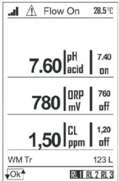
Main Menu ■ Calibration ■ Setup ■ Advanced ■ Alarm list ■ Info/PrimingMeasure view parameters
Instant values parameter view:
- ToolBar #1: WiFi connection, alarm icon, Flow rate status of circulation pump, Temperature
- First measure
- Second measure
- Third measure
- Toolbar#2: Water meter flow rate totalizer
- Toolbar#3: Reed sensor status, relay status.
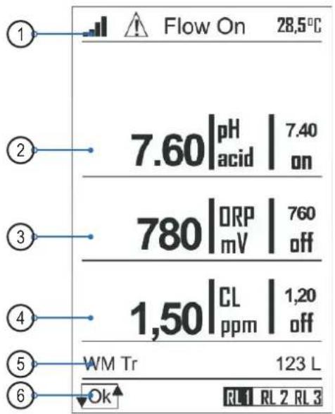
text_image
Flow On 28.5°C 7.60|pH | 7.40 acid on 780|ORP | 760 mV off 1,50|CL | 1,20 ppm off WM Tr 123 L OK RL1 RL2 RL3Icon table:
| Item Icon status Ok/On Icon status Err/Off | ||
| Wi-Fi signal |  |  |
| Alarm Icon Relay (empty) |  | |
| Reed sensor (Probe Holder) |  |  |
| Circulation pump Flow ON Flow OFF | ||
| Tank level1 (empty) LEV | ||
| Tank level2 (empty) LEV | ||
| Aux1 Relay1 |  |  |
| Aux2 Relay2 |  |  |
| Alarm Relay |  | [XSHH] |
| Pump 1 On Off | ||
| Pump 2 On Off | ||
| Over Feed Alarm (OFA) (empty) | OFA | |
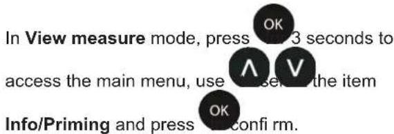
6c1. Info/Priming menu
text_image
In View measure mode, press 3 seconds to access the main menu, use close to the item Info/Priming and press confirm.Main Menu
□ Calibration
□ Setup
□ Advanced
□ Alarm list
■ Info/Priming
Info/Priming
■ Manual download
□ Priming
Select the item Download Manual and press

On the screen will be displayed QR-Code with which you can start downloading the user manual in pdf format
QrCode_Manual

Select the item Priming
The unit show green colour backlight and it is available the manually action of peristaltic pump (Priming action), Relay activation
Priming
■ Pump 1
□ Pump 2
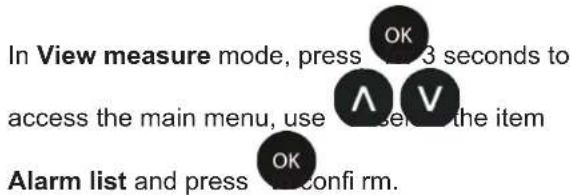
6c2. Alarm list menu
text_image
In View measure mode, press 3 seconds to access the main menu, use A V the item Calibration and press confirm.The Calibration menu consists of five (5) sub-menus:
A. pH probe
B. ORP probe
C. Temperature probe
D. Flow rate sensor
E. Free Chlorine probe
Use a set of an item and press to confirm OK
Main Menu
■ Calibration
□ Setup
□ Advanced
□ Alarm list
□ Info/Priming
Calibration
pH
□ mV
□ Temp
□ Flow Rate sensor
□ Chlorine
A. pH Probe Calibration menu
The pH Probe Calibration menu consists of four (4) sub-menus:
• Automatic: the instrument requires the standard buffer solutions 7 pH, 4 pH or 9.22 pH.
- Manual: the instrument will suggest the buffer solutions from the default values, but the value can be changed.
- Reference: the instrument accepts the calibration of one point with a manually set value.
- Reset (Calibration): the calibrations can be deleted and restored the default values.
Scroll through the menu using , checked item and confirm with .

pH Probe
■ 2 point
□ 1 point
□ Reference
□ Cal. Reset
B. ORP Probe Calibration menu
The ORP Probe Calibration menu consists of three (3) sub-menus:
• Automatic: the instrument requires the standard buffer solutions 465mV.
- Reference: the instrument accepts the calibration of one point with a manually set value.
- Reset (Calibration): the calibrations can be deleted and restored the default values.
Scroll through the menu using a device item and confirm with .

C. Temperature Probe Calibration menu
The Temperature Probe Calibration menu consists of two (2) sub-menus:
- Single (1) Point: the instrument requires a single point calibration by external reference.
- Reset (Calibration): the calibrations can be deleted and restored the default values.
Scroll through the menu using a new item and confirm with .

D. Flow Rate Sensor Calibration menu
The Flow Rate Sensor Calibration menu consists of two (2) sub-menus:
- Flow rate: the instrument requires a single point calibration by external reference.
- Reset sensor: delete all calibrations performed previously.
Scroll through the menu using your device item and confirm with .

Note: The flow calibration is always recommended even if the settings used on Advanced menu are correct, according to the installed sensor model.
ORP Probe
■ 1 point
□ Reference
□ Cal. Reset
Temp. Probe
■ 1 point
□ Cal. Reset
Flow Rate Sensor
■ Flow rate
□ Reset sensor
E. Chlorine Probe Calibration menu
The Chlorine Probe Calibration menu consists of three (3) sub-menus:
- Automatic 1 Point: the instrument requires a single point calibration by external reference.
- Automatic 2 Points: the instrument requires a double point calibration by external reference.
- Reset (Calibration): the calibrations can be deleted and restored the default values.
Scroll through the menu using a device item and confirm with .

CL Probe
■ 1 point
□ 2 points
□ Cal. Reset
6c4. Setup menu
In View measure mode, press OK 3 seconds to access the main menu, use V to select the item Setup and press OK to confirm.
The Setup menu consists of five (5) sub-menus for Hayward Basic* ^A pump (pH+ORP) and six (6) sub-menus for Hayward Plus* ^B pump (pH+ORP+CL):
A. pH Pump
B. ORP (*A: Pump, *B: Measure)
C. CL Pump (*B: Pump)
D. AUX1 Relay
E. AUX2 Relay
F. AUX3 Relay
Main Menu
□ Calibration
■ Setup
□ Advanced
□ Alarm list
□ Info/Priming
Setup\*A
■ pH Pump
□ ORP Pump
□ Aux1 Relay
□ Aux2 Relay
□ Aux3 Relay
Setup\*B
■ pH Pump
□ ORP Measure
□ CL Pump
□ Aux1 Relay
□ Aux2 Relay
□ Aux3 Relay
Below are illustrated the settings required for each sub-menu indicated above.
Use a set of an item and press to confirm OK
To exit the menu, press the instrument will display the question "Save?";
confi rm with . OK
For not saving, select NO using custom with .

Save?
NO
YES
A. pH Pump menu
- SetPoint: Chemical value to maintain into the process
- SetPoint Type:
Acid: the pump doses acid product to reduce pH value
Alca: the pump doses alkaline product to increase pH value - OFA: Over feed alarm timer, maximum activation time
In Advanced menu-> Advanced features
• Time ON: Off..5" to 360" (Default Time ON: 180") (*)
• Time OFF: Off..5" to 360" (Default Time OFF: 360") (*)
Notes:
(*) Time ON and OFF are present if set Type dosing = Timed. Time OFF value must be equal to or greater than Time ON.
B. ORP Pump menu
- SetPoint: Chemical value to maintain into the process
- SetPoint Type:
Rx+: the pump doses chlorine product and increase ORP Rx-: the pump doses no chlorine product and reduce ORP
• OFA: Over feed alarm timer, maximum activation time
In Advanced menu-> Advanced features
- Time ON: Off..5" to 360" (Default Time ON: 180") (*)
- Time OFF: Off..5" to 360" (Default Time OFF: 360") (*)
Notes:
(*) Time ON and OFF are present if set Type dosing = Timed. Time OFF value must be equal to or greater than Time ON.
C. CL Pump menu
- SetPoint: Chemical value to maintain into the process
- SetPoint Type:
CI+: the pump doses chlorine product and increase value CI-: the pump doses no chlorine product and reduce value - OFA: Over feed alarm timer, maximum activation time (range:1-240 min)
In Advanced menu-> Advanced features
• Time ON: Off..5" to 360" (Default Time ON: 180") (*)
• Time OFF: Off..5" to 360" (Default Time OFF: 360") (*)
Notes:
(*) Time ON and OFF are present if set Type dosing = Timed. Time OFF value must be equal to or greater than Time ON.
pH Pump
■ SetPoint 7.40pH
■ SP Type Acid
■ OFA 00'
■ Time On 180"
■ Time Off 360"
■ min Alarm 6 pH
■ Max Alarm 8 pH
ORP Pump
■ SetPoint 740mV
■ SP Type Low
■ OFA 00'
■ Time On 180"
■ Time Off 360"
■ min Alarm 450 mV
■ Max Alarm 850 mV
CL Pump
■ SetPoint 1.20ppm
■ SP Type Low
■ OFA 00'
■ Time On 180"
■ Time Off 360"
■ min Alarm 0.5 ppm
■ Max Alarm 2.0 ppm

HAYWARD®
D. AUX1 Relay
- Aux1 Relay: Set function for:
• pH
- disable
E. AUX2 Relay
- Aux2 Relay: Set function for:
• OFF
• ORP
- Chlorine
F. AUX3 Relay
- Aux1 Relay: Set function for:
• OFF
- Alarm
- ORP
Note: The relays set to the measurement are activated simultaneously with the peristaltic pump.
AUX1 Relay
▶ □ OFF
pH
AUX2 Relay
□ OFF
□ ORP
■ Chlorine
AUX3 Relay
□ OFF
■ Alarm
□ ORP
6c5. Advanced menu
In View measure mode, press OK 3 seconds to access the main menu, use ∧ V to select the item Advanced and press OK confirm.
The Advanced menu consists of six (6) sub-menus:
A. Language/Display
B. Password
C. Advanced Features
D. System Reset
E. FW revision
F. Control Panel
G. Range Probe (setting menu for membrane chlorine probe only)
Main Menu
□ Calibration
□ Setup
■ Advanced
□ Alarm list
□ Info/Priming
Advanced
■ Language/Display
□ Password
□ Advanced Features
□ System Reset
□ FW revision
□ Control Panel
□ Range Probe
Below are illustrated the settings required for each sub-menu indicated above.
Use a set of an item and press to confirm OK
To exit the menu, press the instrument will display the question "Save?";
confi rm with OK
For not saving, select NO using a on form with .


Save?
NO
YES
A. Language/Display menu

text_image
Use a set of an item and press to confirmLanguage/Display
■ Language
□ Display
Language menu:
English is set as default language.
Use A V to select a different language and press OK to confirm. The instrument automatically changes the language of the menu and returns to the previous level.
Language
■ English (default)
□ France
□ Italian
□ German
□ Spanish
□ Cestina
□ Portuguese
□ Dutch
Display menu:
- Contrast: Adjust the contrast light of display
• Red Alarm: Enable/disable red colour of backlight - Green light: Enable/disable green colour of backlight
Display
■ Contrast +10
□ Red Alarm Disable
□ Green light Disable
B. Password function
Set password: set a numeric value.
Note: If the password is present will be displayed Example: "Old password 1234"
Note: To remove the password set four zeros (0000) and press to confirm.
Password
■ Set password
Password menu
Set the value for password, other than 0000.
Scroll through the menu using ∧ ∨ and select the next item using .
Note: To remove the password set four zeros (0000) and press OK to confirm.
Set a password for CAL menu
Enable= access password required
Disable= no need access password required
Set a password for SETUP menu
Enable= access password required
Disable= no need access password required
C. Advanced Features
• Temperature Measure
- Flow Rate Sensor
- Reed Input
- Pump Mode
- WiFi Info
- Power On Delay
- Flow Delay
- Circulation Pump
Below are illustrated the settings required for each sub-menu indicated above.
Temperature Measure
- Selection: Manual or automatic value
- Manual value: please set fixed value
Set password

CAL Menu
□ Disable
■ Enable
SETUP Menu
□ Disable
■ Enable
Advanced Features
■ Temp. Measure
□ Flow Rate Meas.
□ Reed in N. Open
□ Pump Mode
□ WiFi Info
□ P.ON Delay OFF
□ Flow Delay OFF
□ Circ. Pump ON
Temp. Measure
□ Selection Manual
■ Manual 25°C
Flow Rate Sensor
- Sensor type: WPS or KFactor
- Pulse/L – KFactor: set pulse number
- Flow unit
- Total unit
- Reset TR counter
Reed Input
• N. Open: normally open
• N. Close: normally close
Pump Mode
Defi ne the working method for the peristaltic pump onboard.
The value could be:
• OFF
• Proportional (Prop)
- On-Off
- Timed
WiFi Info
Menu WiFi info:
• WiFi Alarm status, Errore con connessione remota
• SSID: service set identifi er
- PSW: password
• IP Address: number address
Power on Delay
Setting time of Power On Delay routine, it is function with countdown timer to disable the measure and dosing regulation when the system switch on, to ensure the right polarization of the probes
- Set timer (range 0..90 minutes)
- Timer= 0 minutes the function is disable
Flow Rate Sensor
■ Sensor type SWF
■ P/L or K-Fac 125
■ Flow Unit m^3/h
■ Total Unit m^3
■ Reset TR counter
Reed Input
■ N.Open
■ N.Closed
Pump Mode
■ pH On-Off
■ ORP Timed
■ Chlorine Prop
WiFi Info
■ WiFi Alarm Off
■ SSID Kommspot H73
■ PSW 12345678
■ IP 192.168.3.1
Power on Delay
00m 01s
Flow Delay
Setting time of Flow Delay routine, it is function with countdown timer to disable the measure and dosing regulation when the flow rate is present again, to ensure the right polarization of the probes
- Set timer (range 0..60 minutes)
- Timer= 0 minutes the function is disable
Circulation pump
Enable/ Disable trigger input of circulation pump, to enable or disable the dosing system.
D. System Reset menu
- Reset unit: reload default parameters.
E. Firmware Revision menu
- Revision: show the firmware revision.
F. Control Panel menu
- Measure input
- Digital input
- Counters
Flow Delay
00m 01s
Circulation pump
□ OFF
■ ON
System Reset
Are You Sure?
No Yes
FW Revision
FW Revision 1.0
Control Panel
■ Measure input
□ Digital input
□ Counters
Measure input: Enable/Disable third pump
Digital input: ON/OFF Input flow rate sensor
Counters: List of internal counters
- Pumps & Signals
- Buttons
- Alarms
- Calibration
- Frequency
G. Range Probe menu (PRO-CHEM-DPHCL2 only)
Set the Chlorine probe range.
Note: The menu setting is available in the ProChem pH+ORP+Chlorine membrane probe only.
Measure input
■ pH probe 58,1 mV
□ ORP probe 700 mV
□ Chlorine P. 32,4μA
□ Flow Rate 5 Hz
□ Temp.PT100 105.5Ohm
Digital input
■ Reed Close
□ Level 1 Open
□ Level 2 Open
□ Cir. Pump ON
Counters
■ Pumps & Signals
□ Buttons
□ Alarm
□ Calibration
□ Frequency
Range Probe
■ 2 ppm
□ 5 ppm
□ 10 ppm
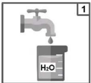
6d. pH probe calibration
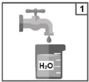
Always begin the calibration procedure with a calibration reset.
text_image
H₂O 1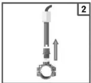
natural_image
Mechanical component diagram showing a piston and crankshaft assembly with an upward arrow (no text or symbols)
text_image
H₂O 3
text_image
7 pH 4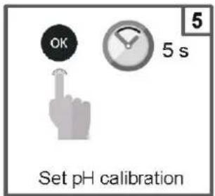
text_image
OK 5 s Set pH calibration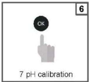
text_image
OK 7 pH calibration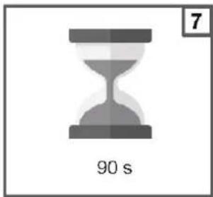
natural_image
Gray hourglass icon with '90 s' label and number 7 in top-right corner (no other text or symbols)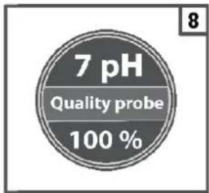
text_image
7 pH Quality probe 100 %
text_image
H₂O 9
text_image
10 4 pH
text_image
OK 4 pH calibration
text_image
90 s 12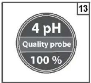
text_image
4 pH Quality probe 100 %
text_image
H₂O 14
natural_image
Mechanical assembly diagram showing a valve and gasket with a downward arrow indicating motion (no text or symbols)
text_image
16 OK Save and exitNote: If you have selected the "1 point cal.", the calibration will be made only in 1 point using the 7pH buffer solution.
Reference calibration
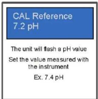
text_image
CAL Reference 7.2 pH The unit will flash a pH value Set the value measured with the instrument Ex. 7.4 pH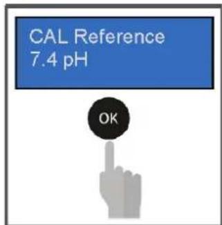
text_image
CAL Reference 7.4 pH OK6e. ORP probe calibration
Always begin the calibration procedure with a calibration reset.
text_image
H₂O 1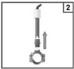
natural_image
Mechanical component diagram showing a shaft and gear assembly with an upward arrow (no text or symbols)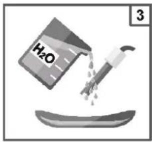
text_image
H₂O 3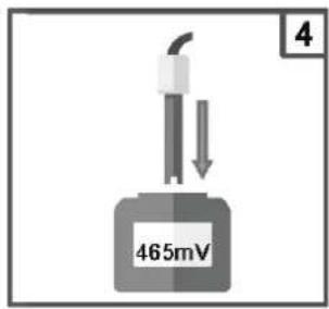
text_image
4 465mV
text_image
OK 5 s Set Redox calibration
text_image
OK 465 mV calibration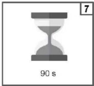
text_image
7 90 s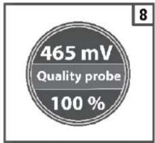
text_image
465 mV Quality probe 100 %
text_image
H₂O 9
natural_image
Mechanical component diagram showing a lever and gear assembly (no text or symbols)
text_image
11 OK Save and exitReference calibration
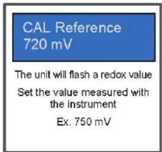
text_image
CAL Reference 720 mV The unit will flash a redox value Set the value measured with the instrument Ex. 750 mV
text_image
CAL Reference 750 mV OK6f. Chlorine calibration
Always begin the calibration procedure with a calibration reset.
chemical
Experimental setup diagram showing a gas collection apparatus connected to a water bath labeled H₂O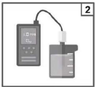
text_image
1.0 2
text_image
OK 3 s Select CI calibration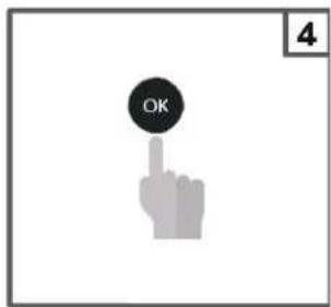
text_image
OK 4
natural_image
Gray hourglass icon with '10 s' label below, no other text or symbols present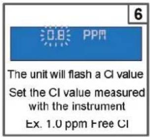
text_image
The unit will flash a CI value Set the CI value measured with the instrument Ex. 1.0 ppm Free CI
text_image
1.0 PPR OK
natural_image
Gray hourglass icon with '10 s' label and number 8 in top-right corner (no other text or symbols)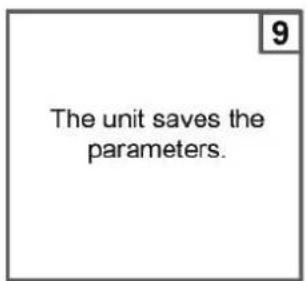
text_image
The unit saves the parameters.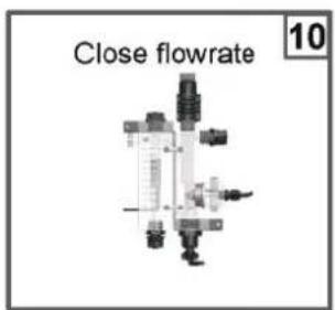
text_image
Close flowrate 10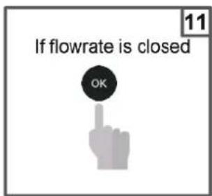
text_image
If flowrate is closed OK
natural_image
Gray hourglass icon with '99 s' label and page number 12 (no other text or symbols)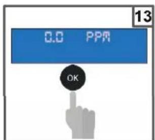
text_image
0.0 PPM OK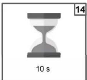
natural_image
Gray hourglass icon with '10 s' label and number 14 in top right corner (no other text or symbols)
text_image
15 Save and exit(Single point calibration the steps routine are from 1 to 8)
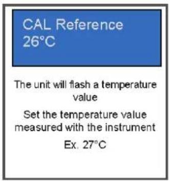
6g. Temperature probe calibration
Always begin the calibration procedure with a calibration reset.
text_image
CAL Reference 26°C The unit will flash a temperature value Set the temperature value measured with the instrument Ex. 27°C
text_image
CAL Reference 27°C OK6h. Flow Rate Sensor Calibration
Note: before running the calibration routine check the water meter setting parameters in the Advanced Features menu.
| Select into calibration Menu Flow Rate sensor, and set Flow rate, to run the calibration routine.Note: in the menu it is present Cal.Reset Item to erase the last calibration and reload default parameters. | Flow rate sensor■ Flow rate■ Cal. Reset | |
| Check the Water meter is stopped, and the flow rate is stationary.Press enter to start the counting pulse | Calibration Flow RateEnter to confirm | |
| Open the flow rate in the Water meter, the unit count the pulses. | Enter to confirmPulses: 00000 | |
| Set the volume liter to count with water meter and press enter to save | Liters: 00001 |
7. WEB CONNECTION SETUP
The ProChem device has internal WiFi card to connect the device to the Hayward web portal or manage the device in direct connection to the Smart Phone or Laptop.

Please use the Qr-Code to download the Hayward ProChem APP:
| IOS Android | |
 |  |
Below step by step create your account and register your device in Hayward web portal to manage by remote.
| Hayward APP Create your Account Confirm | your registration | Add your device in web Portal to scan the Qr-Code | Manange your ProChem via App | |
 |  | Add your security code received by email and confirm your registration | Add device by product QrCode | 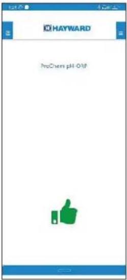 |
-
Follow the wizard menu
-
Complete your town and pool name (min 10 characters)
-
Enjoy your remote pool experience
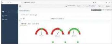
Open the Hayward web site https://www.haywardprochem.com/ to check your device with professional view, below an example of dashboard web.
Insert your Username and Password pre-registered in the APP

text_image
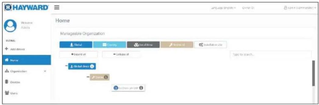
HAYWARD We Build Better." Username Password Log In List your password?Dashboard Home view
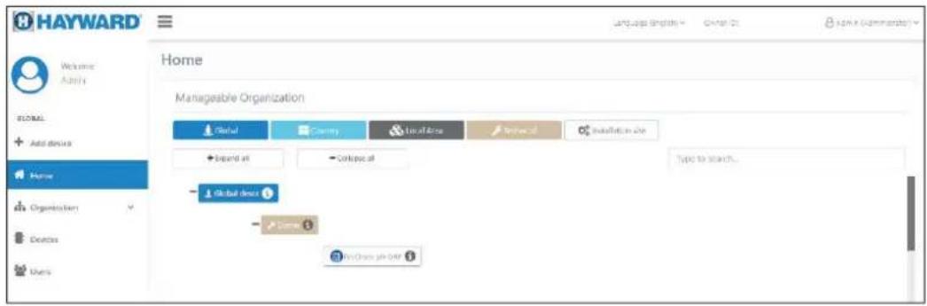
text_image
HAYWARD Welcome Apply Home Manageable Organization Global Cantry Local Area Private Installation the + expand all - Onboard Type to search... Global door - - - Open Door job DAFDashboard device view
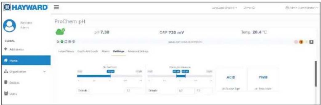
text_image
HAYWARD Welcome Admins ProChem pH pH 7.38 ORP 720 mV Temp: 26.4 °C GLOBAL Add device Home Organization Desks Users Initial Values Graphs Anti-Louch Alimony Settings Advanced Settings ACID FWM pH Range Type pH Rate ValueDirect access to the ProChem device
| Hayward APP Laptop | |||
| Use the Direct Access routine present in the Hayward APP, scan the Qr-Code connection, to easily web pages access. | Connect your laptop to the SSID WiFi Network name. | ||
 |  | Note: Apply the mobile phone permission to use the camera phone and enable the WiFi interface. | Example:SSID: KOMMSPOT-6C8670Password: 12345678Open your browser and write the IP address: 192.168.3.1 |
Device Serial Number:012100/003A6Network Name (SSID):KOMMSPOT-6868F8  | |||
| In the automatic mode open the login web page | Show the login web page | ||
 Login password:0000 Login password:0000 |  Login password:0000 Login password:0000 | ||
 Dashboard Dashboard Dashboard Dashboard | 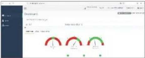 | ||
 Please use pages to set your device Please use pages to set your device Please use pages to set your device Please use pages to set your device |  | ||
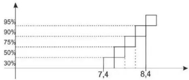
8. DOSING METHOD
Setpoint = 7.4 pH
Dosing mode = Acid
(Prop. Band= 1.0 pH )
Dosing Period= 10 minutes
Acid Dosing method Alcalin Dosing method
other
| X-Axis | Y-Axis (%) | |---|---| | 7.4 | 30 | | 7.4 | 50 | | 7.4 | 75 | | 8.4 | 90 | | 8.4 | 95 |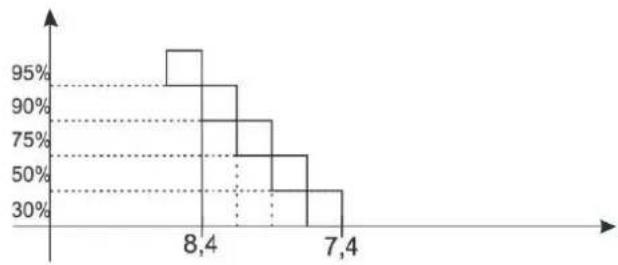
other
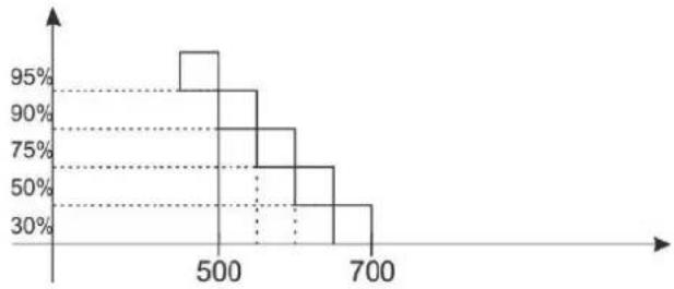
| X-Axis | Percentage (%) | |---|---| | 8,4 | 95 | | 7,4 | 30 |SetPoint = 700 mV
Dosing mode = Low
(Prop.Band= 250mV)
Dosing Period= 10 minutes
Rx+ (Low) dosing method to add chlorine by ORP measure
other
| X-Axis | Y-Axis (%) | |---|---| | 500 | 95 | | 600 | 90 | | 650 | 80 | | 700 | 50 | | 750 | 30 |Rx- (High) dosing method to add chlorine by ORP measure
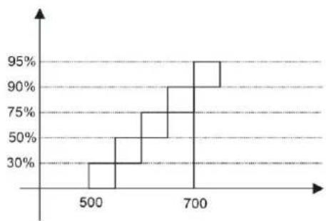
other
| X-Axis | Y-Axis (%) | |---|---| | 500 | 30 | | 600 | 50 | | 700 | 95 | | 720 | 90 |SetPoint = 1.2ppm free Chlorine
Dosing mode = Low
(Prop. Band: 0.8ppm)
Dosing Period= 10 minutes
CL+ (Low) dosing method to add chlorine CL- (High) dosing method to reduce chlorine
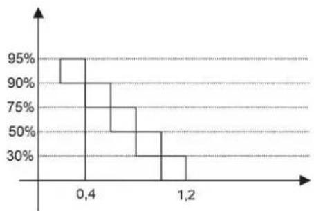
other
| Time Period | Percentage | | ----------- | ---------- | | 0.4 | 95% | | 1.2 | 30% |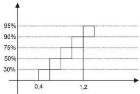
other
| X-Axis | Percentage (%) | |---|---| | 0,4 | 30 | | 1,2 | 95 |Alarm for the pH/ORP Set Point
When the alarm band is set, a work window is created. If the allowed limits are exceeded the alarm relay closes and remains closed until the measurement is reset or OK stressed to deactivate the alarm.
When the OFA time (Over Feed Alarm) is set, the dosing time of Set Point pH/ORP in time is controlled with two alarms:
- First alarm at 70% of the time set is seen on the display, the alarm relay closes.
- Second alarm at 100% of the time set is seen on the display and the alarm relay closes and the pH/ORP pump is blocked.
Press OK eliminate the alarm and initialize the OFA time.
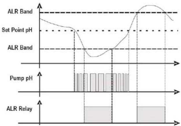
line
| Pump pH | ALR Band | | ------- | -------- | | Low | Low | | Mid | Low | | High | Peak |9. ALARMS
| Alarm Display Actions to do | ||
| Level | Level __7.2_pHLevel __750_mvLevel __1.2_ppm | - Restore Product tank |
| Out of Range measure | pH high, pH I owRX high, Rx I owCL high, CL I ow | - Replace or check the measure probe- Restore measure |
| OFA First Alarm(time >70%) | OFA_AI r_7.2_pHOFA_AI arm blinking | -Push  set set |
| OFA Second Alarm(time 100%) | OFA_STOP_7.2_pHOFA_STOP | -Push  set set |
| Flow Rate | Fl ow_OFF | - Restore Flow Rate |
| Calibration Function | Error __7_pHError __4_pHError __465_mV | - Restore Probe or Buffer solution and repeat calibration procedure |
| System Error | Parameter S error | -AWX2)- Press restore Default parameter- Broken Unit |
| Alarm measure (*1) | High Measure Low Measure | - Adjust the chemical concentration |
(*1 Measure alarm Ranges)
| n | Item Limits | |
| 1 | Temp. Measure min + 10°C | |
| 2 | Temp. Measure Max + 38°C | |
| 3 | pH Measure min 6 pH | |
| 4 | pH Measure Max 8 pH | |
| 5 | O RP Measure min +450 mV | |
| 6 | O RP Measure Max +850 mV |
| PRO-CHEM-DPHCL |
| CL Measure: Min / Max |
| 0 - 5 ppm = 0,5 - 4 ppm |
| PRO-CHEM-DPHCL2 |
| CL Measure: Min / Max |
| 0 - 2 ppm = 0,2 - 1,8 ppm |
| 0 - 5 ppm = 0,5 - 4 ppm |
| 0 - 10 ppm = 0,5 - 8 ppm |
10. SERVICING
During the first 10-15 days, your system will require more attention:
- Check that the pH remains at the ideal level (7.2 to 7.4).
- If the pH is exceptionally unstable and uses a lot of acid, check the alkalinity (see table).
If the balance is highly unstable, contact your pool installer/builder.
REMEMBER that the system needs a certain amount of time to adapt to your pool and will require additional chemicals during the first 3-5 days.
The pool must be regularly maintained and the skimmer baskets emptied whenever necessary.
Also check that your filter is not clogged.
DOSING PUMPS: Regularly check the acid level to ensure that the pump does not run dry. The dosing pump must be checked and serviced at regular intervals. The Santoprene tube of the peristaltic pump has a lifetime of 2 years. We recommend that you change it once a year.
Servicing the probe
The probe must be clean and free from oil, chemical deposits and contamination to function properly. As it is in continuous contact with the water in the pool, the probe may need to be cleaned weekly or monthly, depending on the number of bathers and other specific pool characteristics. A slow response, more frequent pH calibration and inconsistent readings indicate that the probe needs to be cleaned.
To clean the probe, turn off the power to the ProChemDouble.
Unplug the probe connector from the control box, unscrew the probe and carefully remove it from the chamber. Clean the probe bulb with a soft toothbrush and regular toothpaste.
A household washing-up liquid detergent may also be used to remove any oil.
Rinse with fresh water, replace the Teflon tape on the threads, and reinstall the probe.
If the probe continues to give inconsistent readings or requires excessive calibration after it has been cleaned, it should be replaced. The lifetime of the probes is 1 year. We recommend that you calibrate them every month during the season the pool is in use.
Wintering
The ProChemDouble cell, the flow switch, probe and pool piping run the risk of being damaged if the water freezes. In regions that experience long periods of cold weather, be sure to drain all the water from the pump and filter and from the supply and return pipes before winter. Do not remove the control box.
Probe storage
The end of the probe must always be in contact with water or a solution of KCl. If it is removed from the measuring chamber, it should be stored in the plastic cap provided (filled with water). If the storage cap has been mislaid, the probe should be stored separately in a small glass or plastic container with its end immersed in water.
The probe must always be in a frost-free environment.
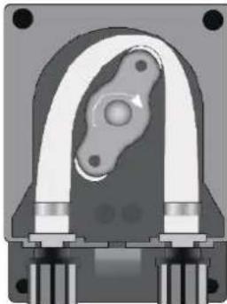
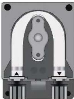
Hose replacement procedure
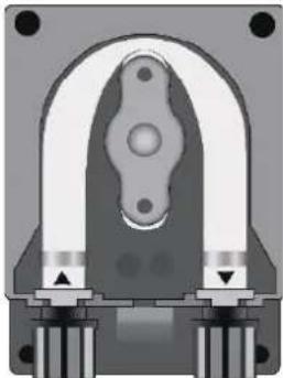
natural_image
Cross-sectional diagram of a mechanical component with symmetrical arch and base (no text or symbols)Open the pump's lid and release the hose by pulling the left connector upward.
natural_image
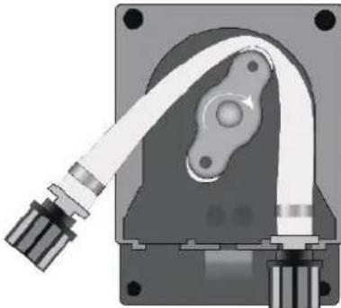
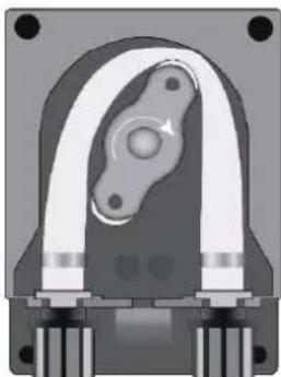
Cross-sectional view of a mechanical component with no visible text or symbolsPosition the roller at 7h05, turning it in the direction of the circular arrow.
natural_image
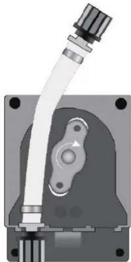
Mechanical component diagram showing a housing with attached cable and mounting base (no text or symbols)Completely release the left connector, holding it taut towards the outside, and turn the roller in the direction of the circular arrow so that the hose is freed up to the right connector.
natural_image
3D rendered mechanical component with central bore and mounting base (no text or symbols)Position the roller at 7h05, turning it in the direction of the circular arrow.
natural_image
Mechanical component diagram showing a pipe fitting and housing (no text or symbols)Insert the left connector into the relative housing and pass the hose under the roller's guide. Turn the roller in the direction of the circular arrow, simultaneously accompanying the hose into the pump's head, until the right connector is reached.
natural_image
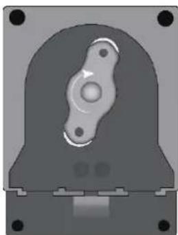
Cross-sectional diagram of a mechanical component with symmetrical U-shaped housing and mounting base (no text or symbols)Close the pump's lid and press its surface hard so that it is properly locked into place.
Storing the pump after use
natural_image
Cross-sectional view of a mechanical component with no visible text or symbolsWhen the regulation device must be stored, clean water should be pumped through the hose in order to rinse it.
Then position the roller at 7h05, turning in the direction indicated by the circular arrow.
These two precautions will facilitate the subsequent reactivation of the unit.
11. TROUBLESHOOTING GUIDE
No display
Check that the On / Off switch is on.
Check the connection cable between the display and the control box.
Check the power supply: 210-230 V\~ 50 Hz.
Check the dosing method if the OFA Alarm show continuously.
Chech the lifetime probe by calibration method.
Chech the running pump by Priming function.
If the problem persists, contact your pool installer/builder.
12. ENVIRONMENTAL INFORMATION
Provision regarding professional waste from electrical and electronic equipment (WEEE). In compliance with directive 2012/19/EU regarding the management of waste from electrical and electronic equipment, this pump must be disposed of at a waste sorting site.
==> for more information contact your dealer.
Good management of waste from electrical and electronic equipment contributes to the prevention of damage to the environment and human health.

LIMITED WARRANTY
All HAYWARD products are covered for manufacturing defects or material defects for a warranty period of 3 years as of date of purchases. Any warranty claim should be accompanied by evidence of purchase, indicating date of purchase. We would therefore advise you to keep your invoice.
The HAYWARD warranty is limited to repair or replacement, as chosen by HAYWARD, of the faulty products, provided that they have been subjected to normal use, in compliance with the guidelines given in their user guides, provided that the products have not been altered in any way, and provided that they have been used exclusively with HAYWARD parts and components. The warranty does not cover damage due to frost and to chemicals. Any other costs (transport, labour, etc.) are excluded from the warranty.
HAYWARD may not be held liable for any direct or indirect damage resulting from incorrect installation, incorrect connection, or incorrect operation of a product.
In order to claim on a warranty and in order to request repair or replacement of an article, please ask your dealer.
No equipment returned to our factory will be accepted without our prior written approval.
Wearing parts are not covered by the warranty.
The wearing parts of the salt water chlorinator listed below must be maintained according to their estimated service life:
Seal set = 2 years
Santoprene tube = 2 years
Roller = 2 years

natural_image
Abstract geometric logo with stylized letter H inside a circular frame (no text or symbols)HAYWARD®
text_image
HEPAWEED 7.40°C 780°C HEPAWEED 7.40°C 1.25°C 780°CCE EAC UK CA

natural_image
Two line icons: one open with an information symbol, the other closed with an open book (no text or symbols present)ProChem Double | pH - ORP - Chlor
HANDBUCH FÜR DEN BESITZER
BITTE BEWAHREN SIE DIESES HANDBUCH ZUM SPÄTEREN NACHSCHLAGEN AUF.
| System Artikel* | PROChem Double pH/ORP (PRO-CHEM-DPHRXG) | PROChem Double pH/ORP/CL-AMP (PRO-CHEM-DPHCL) | PROChem Double pH/ORP/CL-POT (PRO-CHEM-DPHCL2) |
| A | 2 | 2 | 2 |
| B | 2 | 2 | 2 |
| C | 2 | 2 | 2 |
| D | 2 | 1 | 1 |
| E | 5 | 5 | 5 |
| F | 2 | 2 | 2 |
| G | 2 | 2 | 2 |
| H | 1 | 1 | 1 |
| I | 1 | 1 | 1 |
| L | 1 | 1 | 1 |
| M | 1 | 1 | 1 |
| N --- 1 --- | |||
| O --- 1 1 | |||
| P --- 1 --- | |||
| Q --- 1 --- | |||
| R | 1 | 1 | 1 |
| S | 1 | 1 | 1 |
| T | 1 | 1 | 1 |
| U | 1 | 1 | 1 |
| V | 1 | 1 | 1 |
| W | 2 | 2 | 2 |
| X | --- | --- 1 |
flowchart
graph TD
    A["Input"] --> B["Reactor Unit ①"]
    B --> C["Processing Unit ⑦"]
    C --> D["Reactor Unit ⑧"]
    D --> E["Reactor Unit ⑨"]
    E --> F["Digital Monitoring System"]
    F --> G["Output"]
    style A fill:#f9f,stroke:#333
    style G fill:#bbf,stroke:#333
flowchart
graph TD
    A["Input"] --> B["Reactor ①"]
    B --> C["Reactor ②"]
    C --> D["Reactor ③"]
    D --> E["Reactor ④"]
    E --> F["Reactor ⑤"]
    F --> G["Reactor ⑥"]
    G --> H["Reactor ⑦"]
    H --> I["Reactor ⑧"]
    I --> J["Reactor ⑨"]
    J --> K["Reactor ⑩"]
    K --> L["Reactor ⑪"]
    L --> M["Reactor ⑫"]
    M --> N["Reactor ⑬"]
    N --> O["Reactor ⑭"]
PRO-CHEM-DPHCL - ProChem Doppel-pH / ORP / CL-Amperometrisches Installationsplan
natural_image
Diagram showing four sequential steps of a mechanical or structural assembly, with no visible text or symbols.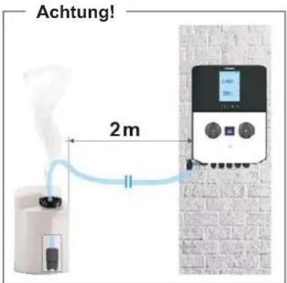
text_image
Achtung! 2mnatural_image
Two black cylindrical devices with screw tips and a red circular warning symbol (no text or labels)text_image
Labeled diagram of a mechanical device with numbered components and measurement scalesSehr wichtig
natural_image
Stacked cylindrical electronic components with a dropper pouring liquid from a tip (no visible text or symbols)natural_image
Technical line drawing of a mechanical component with a cylindrical base and a cylindrical shaft, showing no text or symbols.natural_image
Close-up of hands using a blue pen to apply a small object on a white surface (no visible text or symbols)
natural_image
Close-up of a mechanical component with a red arrow pointing to a cylindrical object (no visible text or symbols)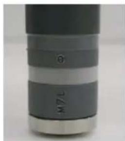
natural_image
Close-up of a cylindrical object with layered bands and a labeled 'M' (no additional text or symbols visible)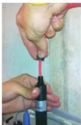
natural_image
Close-up of hands using a red tool to apply a black bottle (no visible text or symbols)
natural_image
Close-up of a hand using a screwdriver to apply material to a black cylindrical component (no visible text or symbols)
HAYWARD®
natural_image
Close-up of hands assembling a blue mechanical component (no visible text or symbols)
natural_image
Close-up of hands using a pink tool to apply liquid onto a black bottle (no visible text or symbols)Sehr wichtig
text_image
Three-panel diagram showing a device with digital display, internal components, and directional arrows indicating process flow.Anschluss des
Etiketts:
natural_image
Front view of a black electronic device casing with mounting holes and internal circuitry (no visible text or symbols)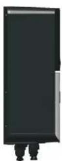
natural_image
Silhouette of a person standing beside a large black rectangular object (no text or symbols visible)
text_image
7.40°C 1.25°C 780°C Air Spin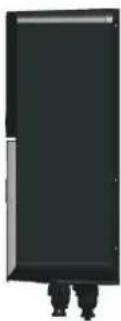
text_image
Flow On 28.5°C 7.60 |pH | 7.40 acid | on 780 |ORP | 760 mV | on WM Tr 123 L Fail RL1 RL2 RL3other
| Metric | Value | | :--- | :--- | | pH | 7.60 | | acid | 7.40 | | on | | | ORP | 780 | | mV | 760 | | off | | | CL | 1,50 | | ppm | 1,20 | | off | | | WM Tr | 123 L | OK RL1 RL2 RL3natural_image
Mechanical component diagram showing a shaft and gear assembly with an upward arrow (no text or symbols)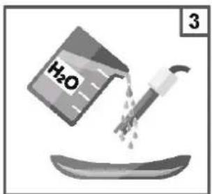
text_image
H₂O 3
text_image
7 pH
text_image
OK 5 s Set pH calibration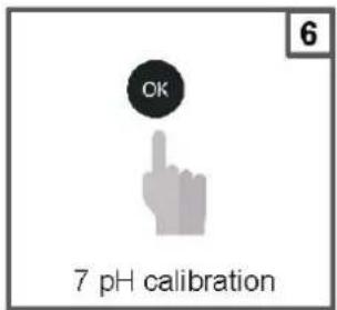
text_image
OK 7 pH calibration
text_image
7 90 s
text_image
7 pH Quality probe 100 %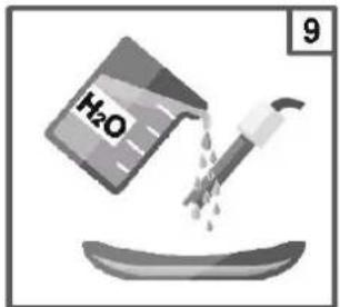
text_image
H₂O 9
text_image
10 4 pH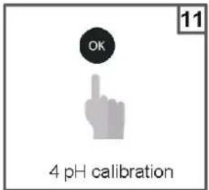
text_image
OK 4 pH calibration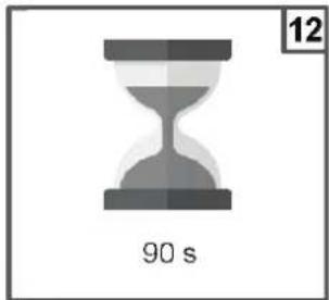
text_image
90 s 12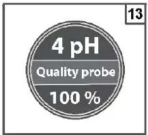
text_image
4 pH Quality probe 100 %
text_image
H₂O 14
natural_image
Mechanical assembly diagram showing a bolt and pipe assembly with a downward arrow indicating motion (no text or symbols)
text_image
16 OK Save and exittext_image
CAL Reference 7.2 pH The unit will flash a pH value Set the value measured with the instrument Ex. 7.4 pH
text_image
CAL Reference 7.4 pH OKnatural_image
Mechanical component diagram showing a shaft and gear assembly with an upward arrow (no text or symbols)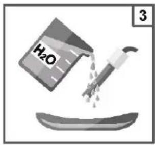
text_image
H₂O 3
text_image
4 465mV
text_image
OK 5 s Set Redox calibration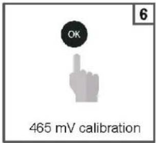
text_image
OK 465 mV calibration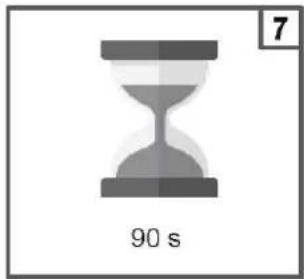
text_image
7 90 s
text_image
465 mV Quality probe 100 %
text_image
H₂O 9
natural_image
Mechanical component diagram showing a lever and gear assembly (no text or symbols)
text_image
11 OK Save and exittext_image
CAL Reference 720 mV The unit will flash a redox value Set the value measured with the instrument Ex. 750 mV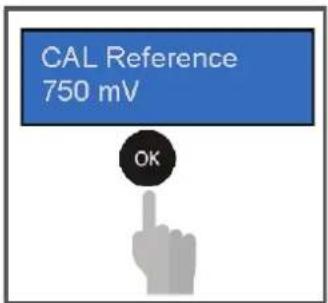
text_image
CAL Reference 750 mV OKchemical
Experimental setup diagram showing a gas collection apparatus connected to a water bath labeled H₂O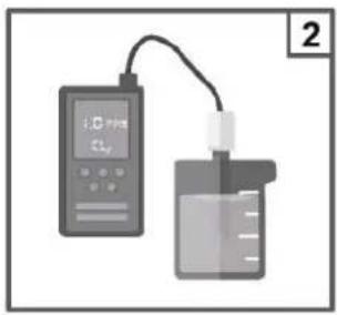
text_image
i.0 mm CLy 2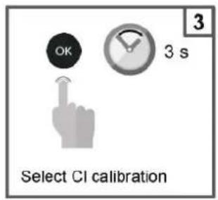
text_image
OK 3 s 3 Select CI calibration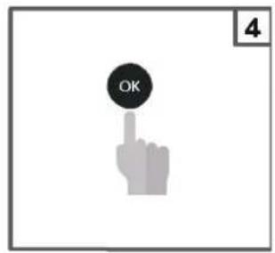
text_image
OK 4
text_image
10 s 5
text_image
The unit will flash a CI value Set the CI value measured with the instrument Ex. 1.0 ppm Free CI
text_image
1.0 PPM OK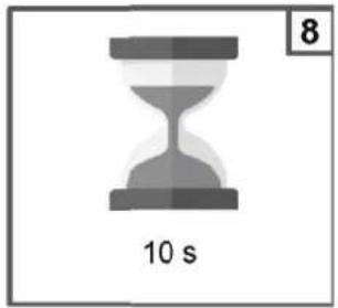
text_image
8 10 s
text_image
The unit saves the parameters.
text_image
Close flowrate 10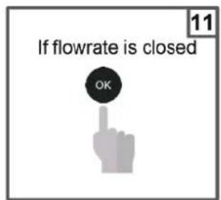
text_image
If flowrate is closed OK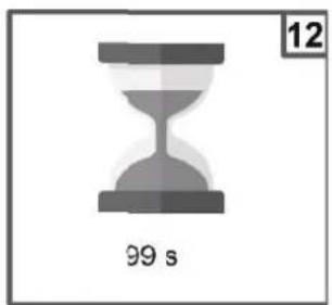
natural_image
Gray hourglass icon with '99 s' label and page number 12 (no other text or symbols)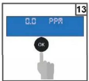
text_image
0.0 PPR OK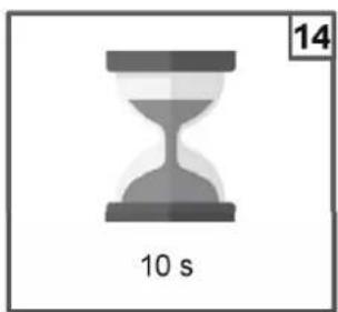
natural_image
Gray hourglass icon with '10 s' label and number 14 in top-right corner (no other text or symbols)
text_image
15 Save and exittext_image
CAL Reference 26°C The unit will flash a temperature value Set the temperature value measured with the instrument Ex. 27°C
text_image
CAL Reference 27°C OKtext_image
HAYWARD We Build Better." Username Password Log in List your password?text_image
HAYWARD Welcome Admin Home Manageable Organization Global Currency Local Drive Imported Installation site + bound at - Collapse at Type to search... Global Drive - - Blue Date job offer Users(Prop. Band= 1,0 pH )
other
| x | y | | ---- | --- | | 8.4 | 95% | | 7.4 | 30% |Sollwert = 700 mV
Sollwert =1,2ppm freies Chlor
natural_image
Cross-sectional view of a mechanical component with symmetrical arms and mounting holes (no text or symbols visible)natural_image
Cross-sectional view of a mechanical component with no visible text or symbolsnatural_image
Mechanical component diagram showing a housing with a cable and housing assembly (no text or symbols visible)natural_image
3D rendered mechanical component with central bore and mounting base (no text or symbols)natural_image
Mechanical assembly diagram showing a pipe fitting and housing component (no text or symbols)natural_image
Cross-sectional diagram of a mechanical component with symmetrical U-shaped housing and mounting points (no text or symbols)natural_image
Mechanical component diagram showing a curved housing with internal components and mounting holes (no text or symbols)natural_image
Abstract geometric logo with stylized letter H inside a circular frame (no text or symbols)HAYWARD®

text_image
HAYWARD 7.40°C 780°C Ply Clean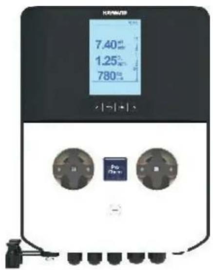
text_image
HV/PM/SP 7.40°C 1.25°C 780°C Pro C -CE EAC UK CA

natural_image
Simple line icon of an open book with an information symbol inside (no text or numbers)
natural_image
Simple line drawing of an open book with no text or symbols visibleProChem Double | pH · ORP · Cloro
MANUAL DEL PROPIETARIO
CONSERVE ESTE MANUAL PARA FUTURAS CONSULTAS


EL EQUIPO ESTÁ DESTINADO A SER UTILIZADO ÚNICAMENTE EN PISCINAS
natural_image
Diagram showing four sequential steps of a mechanical or structural assembly on a brick wall, with no visible text or symbols.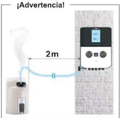
natural_image
Two black cylindrical devices with screw tips and a red circular warning symbol (no text or labels)text_image
Technical diagram of a mechanical device with labeled parts and measurement scaleMuy importante
natural_image
Stacked cylindrical electronic components with a pipette tip, no visible text or symbolsnatural_image
Technical line drawing of a mechanical component with an inset showing a cylindrical part (no text or symbols)
natural_image
Close-up of hands using a blue pen on a small blue surface, no visible text or symbols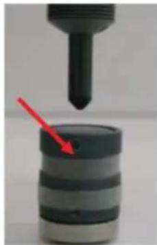
natural_image
Close-up of a mechanical component with a red arrow pointing to a cylindrical object (no visible text or symbols)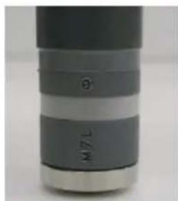
natural_image
Close-up of a cylindrical object with two labeled sections (θ and TLM), no readable text or symbols beyond the markings.
natural_image
Close-up of hands using a red tool to apply a black bottle (no visible text or symbols)
natural_image
Close-up of a hand using a tool to apply a component (no visible text or symbols)
HAYWARD®
natural_image
Close-up of hands assembling a blue mechanical component (no visible text or symbols)
natural_image
Close-up of hands using a pink tool to apply liquid into a black bottle (no visible text or symbols)Muy importante
text_image
Three-panel diagram showing a device with digital display, internal components, and a close-up of the internal structure, each annotated with red arrows indicating motion or change.natural_image
Simple line drawing of a mechanical device with a curved arrow indicating motion (no text or symbols)natural_image
Diagram of a mechanical device with a curved cable and labeled number 3 (no text or symbols on the diagram itself)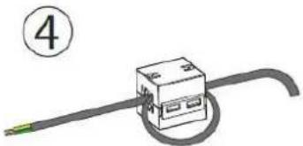
natural_image
Simple line drawing of a cable with a connector and a numbered circle (no text or symbols)ENVUELVA EL CABLE UNA VUELTA
natural_image
Front view of a black electronic device casing with mounting holes and internal grid structure (no visible text or symbols)
natural_image
Exterior view of a modern office building (no signage)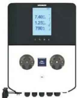
text_image
7.40°C 1.25°C 780°C
natural_image
Pure diagram of a black rectangular object with two small protrusions at the bottom (no text or symbols)text_image
Flow On 28.5°C 7.60 |pH | 7.40 acid | on 780 |ORP | 760 mV | on WM Tr 123 L Fail RL1 RL2 RL3other
| Metric | Value | |---|---| | pH | 7.60 | | acid | 7.40 | | on | | | ORP | 780 | | mV | 760 | | off | | | CL | 1,50 | | ppm | 1,20 | | off | | | WM Tr | 123 L | OK RL1 RL2 RL3natural_image
Mechanical component diagram showing a shaft and gear assembly with an upward arrow (no text or symbols)
text_image
H₂O 3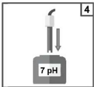
text_image
7 pH 4
text_image
OK 5 s Set pH calibration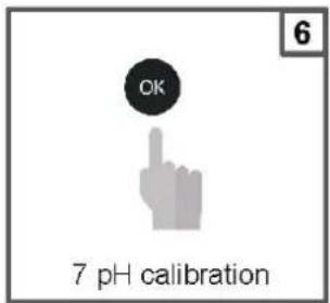
text_image
OK 7 pH calibration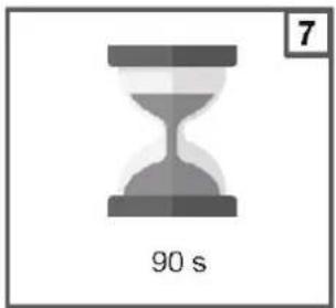
text_image
7 90 s
text_image
7 pH Quality probe 100 %
text_image
H₂O 9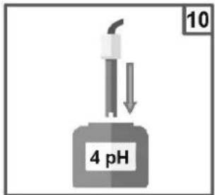
text_image
10 4 pH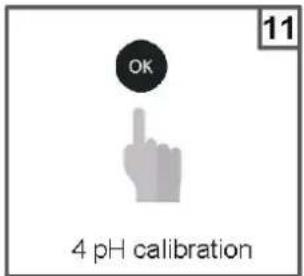
text_image
OK 4 pH calibration
text_image
90 s 12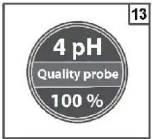
text_image
4 pH Quality probe 100 %
text_image
H₂O 14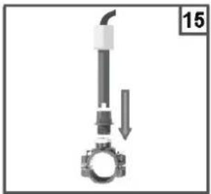
natural_image
Mechanical assembly diagram showing a pipe inserted into a bolt, with a downward arrow indicating motion (no text or symbols)
text_image
16 OK Save and exittext_image
CAL Reference 7.2 pH The unit will flash a pH value Set the value measured with the instrument Ex. 7.4 pH
text_image
CAL Reference 7.4 pH OKnatural_image
Mechanical component diagram showing a shaft and gear assembly with an upward arrow (no text or symbols)
text_image
H₂O 3
text_image
4 465mV
text_image
OK 5 5 s Set Redox calibration
text_image
OK 465 mV calibration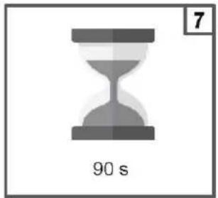
text_image
7 90 s
text_image
465 mV Quality probe 100 %
text_image
H₂O 9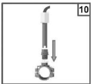
natural_image
Mechanical assembly diagram showing a pipe inserted into a gear with a downward arrow indicating motion (no text or symbols)
text_image
11 OK Save and exittext_image
CAL Reference 720 mV The unit will flash a redox value Set the value measured with the instrument Ex. 750 mV
text_image
CAL Reference 750 mV OKchemical
Chemical apparatus diagram showing a gas collection setup with H2O solution and labeled component 1
text_image
i.0 mm CLy 2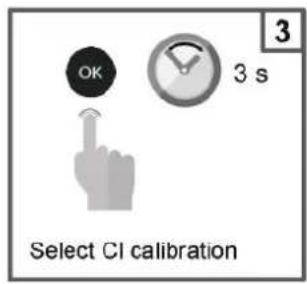
text_image
OK 3 s 3 Select CI calibration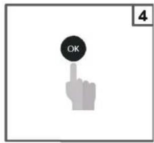
text_image
OK 4
text_image
10 s 5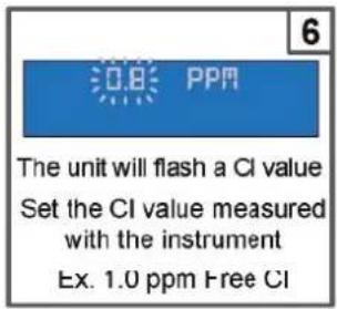
text_image
The unit will flash a CI value Set the CI value measured with the instrument Ex. 1.0 ppm Free CI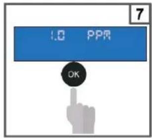
text_image
1.0 PPR OK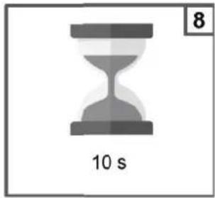
text_image
8 10 s
text_image
The unit saves the parameters.
text_image
Close flowrate 10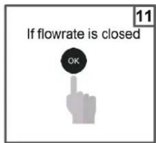
text_image
If flowrate is closed OK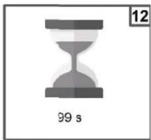
natural_image
Gray hourglass icon with '99 s' label and page number 12 (no other text or symbols)
text_image
0.0 PPR OK
natural_image
Gray hourglass icon with '10 s' label and number 14 in top-right corner (no other text or symbols)
text_image
15 Save and exittext_image
CAL Reference 26°C The unit will flash a temperature value Set the temperature value measured with the instrument Ex. 27°C
text_image
CAL Reference 27°C OKtext_image
HAYWARD We Build Better." Unknown Password Log in List your password?other
| X-Axis | Percentage (%) | |---|---| | 0.4 | 95 | | 0.4 | 90 | | 0.4 | 75 | | 0.4 | 50 | | 1.2 | 30 |natural_image
Cross-sectional view of a mechanical clamp or bracket component (no visible text or symbols)natural_image
Cross-sectional view of a mechanical component with no visible text or symbolsnatural_image
Mechanical component diagram showing a housing with attached cable and mounting base (no text or symbols)natural_image
3D rendered mechanical component with central bore and mounting base (no text or symbols)natural_image
Mechanical component diagram showing a shaft and housing assembly with no visible text or symbolsnatural_image
Cross-sectional diagram of a mechanical component with symmetrical U-shaped housing and mounting base (no text or symbols)natural_image
Cross-sectional diagram of a mechanical component with no visible text or symbolsnatural_image
Abstract geometric logo with stylized letter H inside a circular frame (no text or symbols)HAYWARD®

text_image
HEPAWEED 7.40°C 780°C HePAWEED 7.40°C 1.25°C 780°CCE EAC UK CA

natural_image
Two line icons: one open with an information symbol, the other closed with an open book (no text or symbols present)ProChem Double | pH · ORP · Chlore
MANUEL DU PROPRIÉTAIRE
VEUILLEZ CONSERVER CE MANUEL POUR TOUTE RÉFÉRENCE ULTÉRIEURE


L'ÉQUIPEMENT EST DESTINÉ À ÊTRE UTILISÉ UNIQUEMENT DANS LES PISCINES
| Système Élement* | PROChem Double pH/ORP (PRO-CHEM-DPHRXG) | PROChem Double pH/ORP/CL-AMP (PRO-CHEM-DPHCL) | PROChem Double pH/ORP/CL-POT (PRO-CHEM-DPHCL2) |
| A | 2 | 2 | 2 |
| B | 2 | 2 | 2 |
| C | 2 | 2 | 2 |
| D | 2 | 1 | 1 |
| E | 5 | 5 | 5 |
| F | 2 | 2 | 2 |
| G | 2 | 2 | 2 |
| H | 1 | 1 | 1 |
| I | 1 | 1 | 1 |
| L | 1 | 1 | 1 |
| M | 1 | 1 | 1 |
| N --- 1 --- | |||
| O --- 1 1 | |||
| P --- 1 --- | |||
| Q --- 1 --- | |||
| R | 1 | 1 | 1 |
| S | 1 | 1 | 1 |
| T | 1 | 1 | 1 |
| U | 1 | 1 | 1 |
| V | 1 | 1 | 1 |
| W | 2 | 2 | 2 |
| X --- | --- 1 |
3b. Installation murale
natural_image
Diagram showing four sequential steps of a mechanical or structural assembly on a brick wall, with no visible text or symbols.
text_image
Avertissement ! 2mtext_image
Technical diagram of a mechanical device with labeled parts, including pressure gauge and adjustment knobsTrès important
natural_image
Stacked cylindrical electronic devices with a pipette tip, no visible text or symbols
HAYWARD®
natural_image
Technical line drawing of a mechanical component with an inset showing a cylindrical part (no text or symbols)natural_image
Close-up of hands using a blue pen to apply a blue adhesive on a white surface (no visible text or symbols)
natural_image
Close-up of a mechanical component with a red arrow pointing to a cylindrical object (no text or symbols visible)
natural_image
Close-up of a cylindrical mechanical component with no visible text or symbols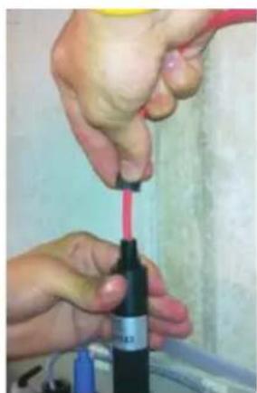
natural_image
Close-up of hands using a red tool to apply a black bottle (no visible text or symbols)
natural_image
Close-up of a hand using a tool to adjust or install a small electronic component (no visible text or symbols)
HAYWARD®
natural_image
Close-up of hands assembling a blue mechanical component (no visible text or symbols)
natural_image
Close-up of hands using a handheld tool to apply liquid, no visible text or symbolsTrès important
text_image
Three-panel diagram showing a device with digital display, internal components, and a close-up of the interior with red arrows indicating motion or change.natural_image
Diagram of a cable being inserted into a device, showing motion with no text or symbols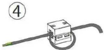
natural_image
Simple line drawing of a mechanical component with a curved shaft and circular end (no text or symbols)ENROULER LE CÂBLE POUR UN TOUR
natural_image
Front view of a black electronic device casing with mounting holes and internal grid structure (no visible text or symbols)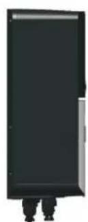
natural_image
Simple black rectangular object with a small protrusion at the bottom (no text or symbols visible)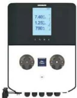
text_image
7.40°C 1.25°C 780°C Air Spin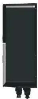
natural_image
Exterior view of a modern office building (no signage)
HAYWARD®
6. CONFIGURATION ET FONCTIONNEMENT
text_image
Flow On 28.5°C 7.60 |pH | 7.40 acid | on 780 |ORP | 760 mV | on WM Tr 123 L Fail RL1 RL2 RL3other
| Parameter | Value | |---|---| | pH | 7.60 | | acid | 7.40 | | on | | | ORP | 780 | | mV | 760 | | off | | | CL | 1,50 | | ppm | 1,20 | | off | | | WM Tr | 123 L | OK RL1 RL2 RL3Révision FW (FirmWare)
Révision FW 1.0
natural_image
Mechanical component diagram showing a shaft and gear assembly with an upward arrow (no text or symbols)
text_image
H₂O 3
text_image
7 pH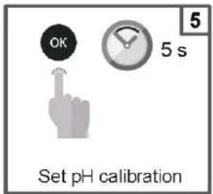
text_image
OK 5 s Set pH calibration
text_image
OK 7 pH calibration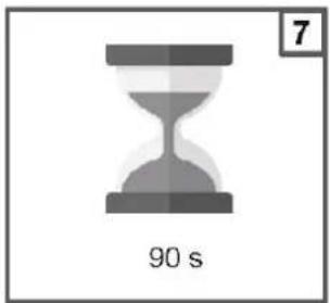
text_image
7 90 s
text_image
7 pH Quality probe 100 %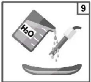
text_image
H₂O 9
text_image
10 4 pH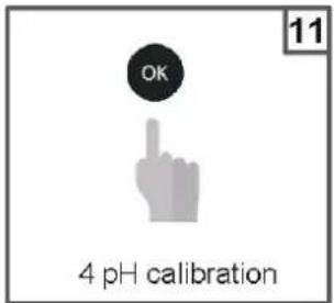
text_image
OK 4 pH calibration
text_image
90 s 12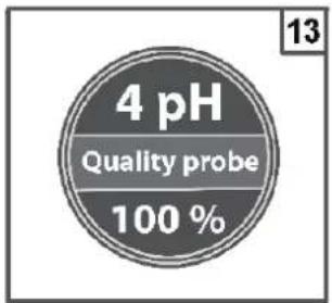
text_image
4 pH Quality probe 100 %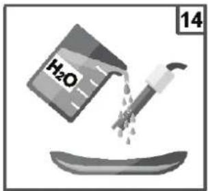
text_image
H₂O 14
natural_image
Mechanical component diagram showing a valve and gasket assembly (no text or symbols)
text_image
16 OK Save and exittext_image
CAL Reference 7.2 pH The unit will flash a pH value Set the value measured with the instrument Ex. 7.4 pH
text_image
CAL Reference 7.4 pH OKnatural_image
Mechanical component diagram showing a shaft and gear assembly with an upward arrow (no text or symbols)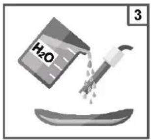
text_image
H₂O 3
text_image
4 465mV
text_image
OK 5 5 s Set Redox calibration
text_image
OK 465 mV calibration
text_image
7 90 s
text_image
465 mV Quality probe 100 %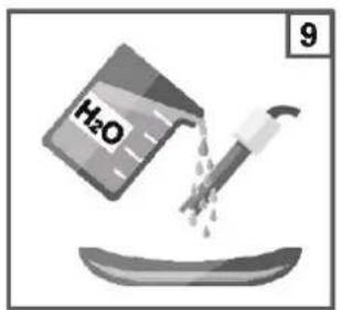
text_image
H₂O 9
natural_image
Mechanical assembly diagram showing a pipe inserted into a gear with a downward arrow indicating motion (no text or symbols)
text_image
11 OK Save and exittext_image
CAL Reference 720 mV The unit will flash a redox value Set the value measured with the instrument Ex. 750 mV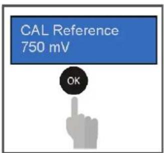
text_image
CAL Reference 750 mV OK6f. Étalonnage chlore
chemical
Chemical apparatus diagram showing a gas collection setup with H2O solution and labeled component 1
text_image
i: 0.1mm CLy 2
text_image
OK 3 s Select CI calibration
text_image
OK 4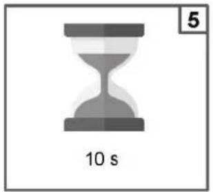
text_image
10 s 5
text_image
The unit will flash a CI value Set the CI value measured with the instrument Ex. 1.0 ppm Free CI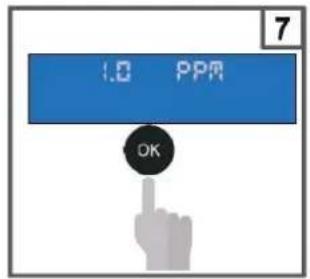
text_image
1.0 PPM OK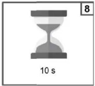
text_image
8 10 s
text_image
The unit saves the parameters.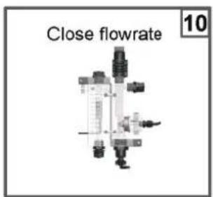
text_image
Close flowrate 10
text_image
If flowrate is closed OK
natural_image
Gray hourglass icon with '99 s' label and number 12 in top-right corner (no other text or symbols)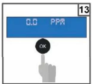
text_image
0.0 PPR OK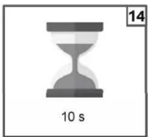
natural_image
Gray hourglass icon with '10 s' label and number 14 in top-right corner (no other text or symbols)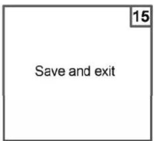
text_image
15 Save and exittext_image
CAL Reference 26°C The unit will flash a temperature value Set the temperature value measured with the instrument Ex. 27°C
text_image
CAL Reference 27°C OKtext_image
HAYWARD We Build Better." Username Password Log in List your password?text_image
HAYWARD Welcome Active Home Manageable Organization Global Currency localAir Newark Installation site + bound at - Onlook at Type to search... Global Direct - - For Change p# 047other
| Time Period | Percentage | | ----------- | ---------- | | 0.4 | 95% | | 1.2 | 30% |natural_image
Cross-sectional diagram of a mechanical component with symmetrical arms and mounting holes (no text or symbols)natural_image
Cross-sectional view of a mechanical component with no visible text or symbolsnatural_image
Mechanical component diagram showing a housing with attached cable and mounting base (no text or symbols)natural_image
3D rendered mechanical component with central bore and mounting base (no text or symbols)natural_image
Mechanical assembly diagram showing a pipe fitting and housing component (no text or symbols)natural_image
Cross-sectional diagram of a mechanical component with symmetrical arch and base (no text or symbols)natural_image
Cross-sectional diagram of a mechanical component with no visible text or symbolsnatural_image
Abstract geometric logo with stylized letter H inside a circular frame (no text or symbols)HAYWARD®

text_image
HEPAWEED 7.40°C 780°C HePAWEED 7.40°C 1.25°C 780°CCE EAC UK CA

natural_image
Two line icons: one open with an information symbol, the other closed with an open book (no text or symbols present)ProChem Double | pH · ORP · Cloro
MANUALE D'USO
| Componente ^1 Sistema | PROChem Double pH/ORP (PRO-CHEM-DPHRXG) | PROChem Double pH/ORP/CL-AMP (PRO-CHEM-DPHCL) | PROChem Double pH/ORP/CL-POT (PRO-CHEM-DPHCL2) |
| A | 2 | 2 | 2 |
| B | 2 | 2 | 2 |
| C | 2 | 2 | 2 |
| D | 2 | 1 | 1 |
| E | 5 | 5 | 5 |
| F | 2 | 2 | 2 |
| G | 2 | 2 | 2 |
| H | 1 | 1 | 1 |
| I | 1 | 1 | 1 |
| L | 1 | 1 | 1 |
| M | 1 | 1 | 1 |
| N --- 1 --- | |||
| O --- 1 1 | |||
| P --- 1 --- | |||
| Q --- 1 --- | |||
| R | 1 | 1 | 1 |
| S | 1 | 1 | 1 |
| T | 1 | 1 | 1 |
| U | 1 | 1 | 1 |
| V | 1 | 1 | 1 |
| W | 2 | 2 | 2 |
| X | --- | --- 1 |
natural_image
Diagram showing a mechanical assembly or mounting process with arrows indicating direction, no text or symbols present.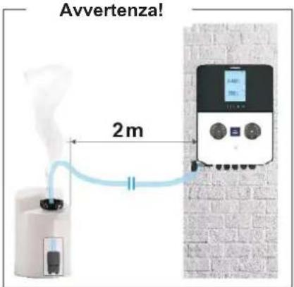
text_image
Technical diagram of a mechanical device with labeled parts, including pressure gauge and adjustment knobsMolto importante
natural_image
Stacked cylindrical electronic devices with a pipette tip, no visible text or symbols
HAYWARD®
natural_image
Technical line drawing of a mechanical component with a cylindrical base and a cylindrical shaft, showing no text or symbols.natural_image
Close-up of hands using a blue pen to apply material on a white surface (no visible text or symbols)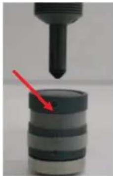
natural_image
Close-up of a mechanical component with a red arrow pointing to a cylindrical object (no text or symbols visible)
natural_image
Close-up of a cylindrical mechanical component with no visible text or symbols
natural_image
Close-up of hands using a red tool to apply a black bottle (no visible text or symbols)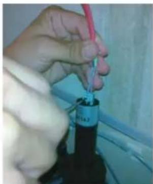
natural_image
Close-up of hands using a tool to apply a black plastic bottle (no visible text or symbols)
HAYWARD®
natural_image
Close-up of hands assembling a mechanical component (no visible text or symbols)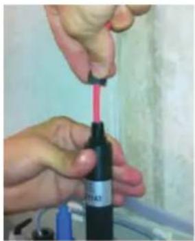
natural_image
Close-up of hands using a red tool to apply liquid onto a black bottle (no visible text or symbols)Molto importante
text_image
Three-panel diagram showing a device with digital display, internal components, and directional arrows indicating process flow.natural_image
Diagram of a mechanical device with a curved arrow indicating motion or force (no text or symbols)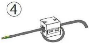
natural_image
Simple line drawing of a cable with a box and cord, no text or symbols presentAVVOLGERE IL CAVO DI UN GIRO
natural_image
Front view of a black electronic device casing with mounting holes and internal circuitry (no visible text or symbols)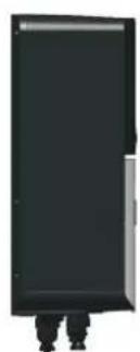
natural_image
Simple black rectangular object with two small protrusions at the bottom (no text or symbols)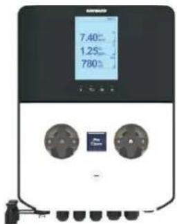
text_image
7.40°C 1.25°C 780°C Air Spin -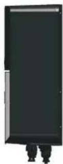
natural_image
Black rectangular object with two small human figures at the bottom (no text or symbols visible)
HAYWARD®
6. IMPOSTAZIONE E FUNZIONAMENTO
text_image
Flow On 28.5°C 7.60 |pH | 7.40 acid | on 780 |ORP | 760 mV | on WM Tr 123 L Fail RL1 RL2 RL3other
| Metric | Value | | :--- | :--- | | pH | 7.60 | | acid | 7.40 | | on | | | ORP | 780 | | mV | 760 | | off | | | CL | 1,50 | | ppm | 1,20 | | off | | | WM Tr | 123 L | OK RL2 RL3 28.5℃natural_image
Mechanical component diagram showing a piston and crankshaft assembly with an upward arrow (no text or symbols)
text_image
H₂O 3
text_image
7 pH
text_image
OK 5 s Set pH calibration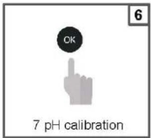
text_image
OK 7 pH calibration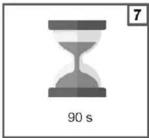
natural_image
Gray hourglass icon with '90 s' label and number 7 in top-right corner (no other text or symbols)
text_image
7 pH Quality probe 100 %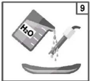
text_image
H₂O 9
text_image
10 4 pH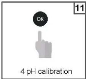
text_image
OK 4 pH calibration
text_image
90 s 12
text_image
4 pH Quality probe 100 %
text_image
H₂O 14
natural_image
Mechanical assembly diagram showing a valve and gasket with a downward arrow indicating motion (no text or symbols)
text_image
16 OK Save and exittext_image
CAL Reference 7.2 pH The unit will flash a pH value Set the value measured with the instrument Ex. 7.4 pH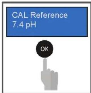
text_image
CAL Reference 7.4 pH OKnatural_image
Mechanical component diagram showing a shaft and gear assembly with an upward arrow (no text or symbols)
text_image
H₂O 3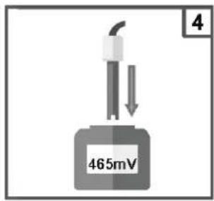
text_image
465mV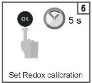
text_image
OK 5 5 s Set Redox calibration
text_image
OK 465 mV calibration
text_image
7 90 s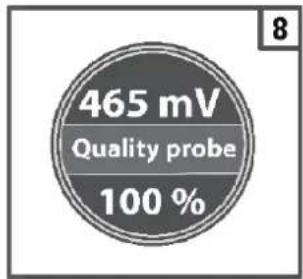
text_image
465 mV Quality probe 100 %
text_image
H₂O 9
natural_image
Mechanical assembly diagram showing a pipe inserted into a gear with a downward arrow indicating motion (no text or symbols)
text_image
11 OK Save and exittext_image
CAL Reference 720 mV The unit will flash a redox value Set the value measured with the instrument Ex. 750 mV
text_image
CAL Reference 750 mV OKchemical
Experimental setup diagram showing a gas collection apparatus connected to a water bath labeled H₂O
text_image
1.0 ppm CL₂ 2
text_image
OK 3 s 3 Select CI calibration
text_image
OK 4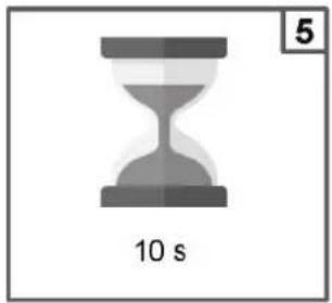
text_image
10 s 5
text_image
The unit will flash a CI value Set the CI value measured with the instrument Ex. 1.0 ppm Free CI
text_image
1.0 PPR OK
natural_image
Gray hourglass icon with '10 s' label and number 8 in top-right corner (no other text or symbols)
text_image
The unit saves the parameters.
text_image
Close flowrate 10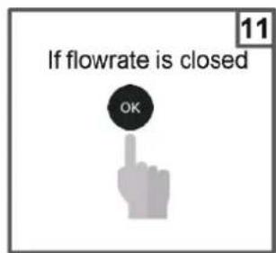
text_image
If flowrate is closed OK
natural_image
Gray hourglass icon with '99 s' label below, no other text or symbols present
text_image
0.0 PPR OK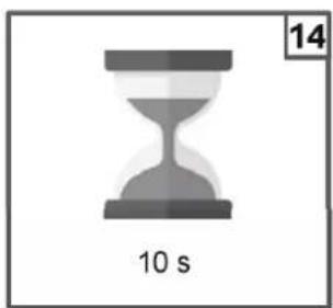
natural_image
Gray hourglass icon with '10 s' label and number 14 in top-right corner (no other text or symbols)
text_image
15 Save and exittext_image
CAL Reference 26°C The unit will flash a temperature value Set the temperature value measured with the instrument Ex. 27°C
text_image
CAL Reference 27°C OKtext_image
HAYWARD We Build Better." Username Password Log in List your password?Dashboard Home

text_image
HAYWARD Welcome Admin Home Manageable Organization Global Canary LocalDrive Impact Installation Site + Brand at - Collapse at Type to Search... Global Drive - - Birchons plc DAF(Banda prop. = 1,0 pH)
other
| x | y | | ---- | --- | | 8.4 | 95% | | 7.4 | 30% |Setpoint= 700 mV
other
| X-Axis | Percentage (%) | |---|---| | 0.4 | 95 | | 0.4 | 90 | | 0.4 | 75 | | 0.4 | 50 | | 1.2 | 30 |other
| X-Axis | Y-Axis (%) | |---|---| | 0.4 | 30 | | 0.4 | 50 | | 0.4 | 75 | | 1.2 | 90 | | 1.2 | 95 |Allarme setpoint pH/ORP
line
| pH Level | Banda ALR | | -------------- | --------- | | Setpoint pH | High | | Banda ALR | Low | | Pompa pH | Medium | | Banda ALR | High |9. ALLARMI
natural_image
Cross-sectional view of a mechanical component with symmetrical arch and mounting holes (no text or symbols)natural_image
Cross-sectional view of a mechanical component with no visible text or symbolsnatural_image
Mechanical component diagram showing a housing with a cable and housing assembly (no text or symbols visible)natural_image
3D rendered mechanical component with central bore and mounting base (no text or symbols)natural_image
Mechanical component diagram showing a pipe fitting and housing (no text or symbols)natural_image
Cross-sectional diagram of a mechanical component with symmetrical U-shaped housing and mounting base (no text or symbols)natural_image
Cross-sectional diagram of a mechanical component with no visible text or symbolsnatural_image
Abstract geometric logo with stylized letter H inside a circular frame (no text or symbols)HAYWARD®

text_image
HEPAWEED 7.40°C 780°C HePAWEED 7.40°C 1.25°C 780°CCE EAC UK CA

natural_image
Two line icons: one open with an information symbol, the other closed with an open book (no text or symbols present)| Sistema Item* | PROChem Double pH/ORP (PRO-CHEM-DPHRXG) | PROChem Double pH/ORP/CL-AMP (PRO-CHEM-DPHCL) | PROChem Double pH/ORP/CL-POT (PRO-CHEM-DPHCL2) |
| A | 2 | 2 | 2 |
| B | 2 | 2 | 2 |
| C | 2 | 2 | 2 |
| D | 2 | 1 | 1 |
| E | 5 | 5 | 5 |
| F | 2 | 2 | 2 |
| G | 2 | 2 | 2 |
| H | 1 | 1 | 1 |
| I | 1 | 1 | 1 |
| L | 1 | 1 | 1 |
| M | 1 | 1 | 1 |
| N --- 1 --- | |||
| O --- 1 1 | |||
| P --- 1 --- | |||
| Q --- 1 --- | |||
| R | 1 | 1 | 1 |
| S | 1 | 1 | 1 |
| T | 1 | 1 | 1 |
| U | 1 | 1 | 1 |
| V | 1 | 1 | 1 |
| W | 2 | 2 | 2 |
| X | --- | --- 1 |
natural_image
Diagram showing four sequential steps of a mechanical or structural assembly on a brick wall, with no visible text or symbols.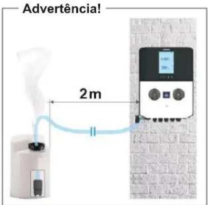
natural_image
Two black cylindrical devices with screw tips and a red circular warning symbol (no text or labels)text_image
Technical diagram of a mechanical device with labeled parts and measurement scaleMuito importante
natural_image
Stacked cylindrical electronic components with a pipette tip, no visible text or symbolsnatural_image
Technical line drawing of a mechanical component with an inset showing a cylindrical part (no text or symbols)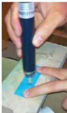
natural_image
Close-up of hands using a blue pen on a small object, no visible text or symbols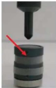
natural_image
Close-up of a mechanical component with a red arrow pointing to a cylindrical object (no visible text or symbols)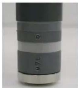
natural_image
Close-up of a cylindrical object with layered bands and a labeled 'L/M' section (no additional text or symbols visible)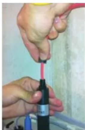
natural_image
Close-up of hands using a red tool to apply a black bottle (no visible text or symbols)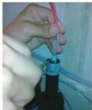
natural_image
Close-up of a hand using a tool to apply a component, no visible text or symbols
HAYWARD®
natural_image
Close-up of hands assembling a blue mechanical component (no visible text or symbols)
natural_image
Close-up of hands using a pink tool to apply a red substance from a black bottle (no visible text or symbols)Muito importante
text_image
Three-panel diagram showing a device with digital display, internal components, and directional arrows indicating process flow.natural_image
Simple line drawing of a cable being inserted into a device, no text or symbols present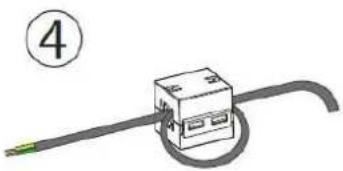
natural_image
Simple line drawing of a cable with a box and a green cable, no text or symbols presentENROLAR O CABO COM UMA VOLTA
natural_image
Front view of a black electronic device casing with mounting holes and internal circuitry (no visible text or symbols)
natural_image
Simple black rectangular object with a small protrusion at the bottom (no text or symbols visible)
text_image
7.40°C 1.25°C 780°C Apo Cm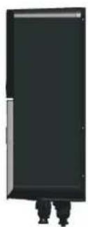
natural_image
Exterior view of a modern office building (no signage)text_image
Flow On 28.5°C 7.60 |pH | 7.40 acid | on 780 |ORP | 760 mV | on WM Tr 123 L Fail RL1 RL2 RL3other
| Metric | Value | | :--- | :--- | | pH | 7.60 | | acid | 7.40 | | on | | | ORP | 780 | | mV | 760 | | off | | | CL | 1,50 | | ppm | 1,20 | | off | | | WM Tr | 123 L | OK RL1 RL2 RL3text_image
Salvar? NO YESA. Menu da bomba de pH
text_image
Salvar? NO YESA. Menu Idioma/Ecrã
natural_image
Mechanical component diagram showing a piston and crankshaft assembly (no text or symbols)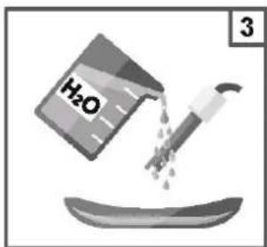
text_image
H₂O 3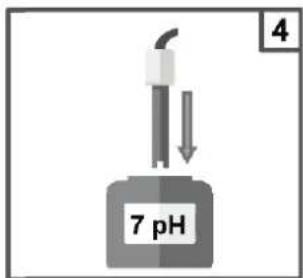
text_image
7 pH
text_image
OK 5 s Set pH calibration
text_image
OK 7 pH calibration
text_image
7 90 s
text_image
7 pH Quality probe 100 %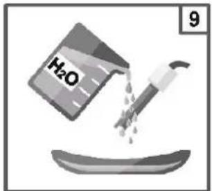
text_image
H₂O 9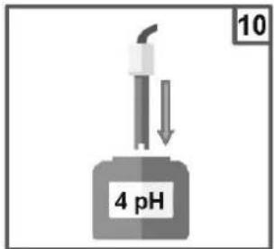
text_image
10 4 pH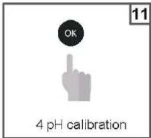
text_image
OK 4 pH calibration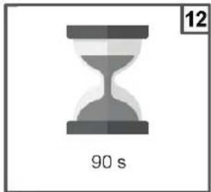
text_image
90 s 12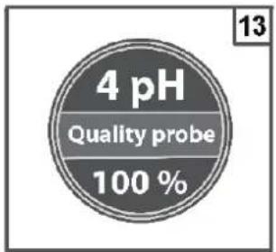
text_image
4 pH Quality probe 100 %
text_image
H₂O 14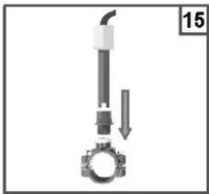
natural_image
Mechanical assembly diagram showing a valve and gasket with a downward arrow indicating motion (no text or symbols)
text_image
16 OK Save and exittext_image
CAL Reference 7.2 pH The unit will flash a pH value Set the value measured with the instrument Ex. 7.4 pH
text_image
CAL Reference 7.4 pH OKnatural_image
Mechanical component diagram showing a piston and crankshaft assembly with an upward arrow (no text or symbols)
text_image
H₂O 3
text_image
465mV
text_image
OK 5 s Set Redox calibration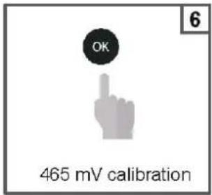
text_image
OK 465 mV calibration
text_image
7 90 s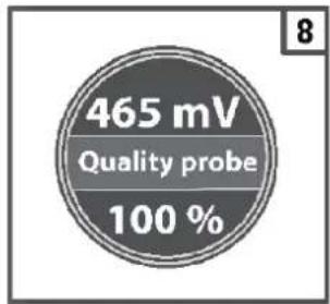
text_image
465 mV Quality probe 100 %
text_image
H₂O 9
natural_image
Mechanical component diagram showing a lever and gear assembly (no text or symbols)
text_image
11 OK Save and exittext_image
CAL Reference 720 mV The unit will flash a redox value Set the value measured with the instrument Ex. 750 mV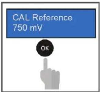
text_image
CAL Reference 750 mV OKchemical
Experimental setup diagram showing a gas collection apparatus with H2O solution and connected tubing
text_image
Diagram showing a digital device connected to a beaker with liquid, labeled with Chinese characters.
text_image
OK 3 s Select CI calibration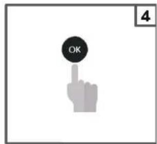
text_image
OK 4
text_image
10 s 5
text_image
6 PPM The unit will flash a CI value Set the CI value measured with the instrument Ex. 1.0 ppm Free CI
text_image
1.0 PPR OK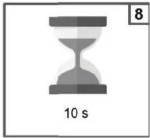
natural_image
Gray hourglass icon with '10 s' label and number 8 in top-right corner (no other text or symbols)
text_image
The unit saves the parameters.
text_image
Close flowrate 10
text_image
If flowrate is closed OK
natural_image
Gray hourglass icon with '99 s' label and number 12 in top right corner (no other text or symbols)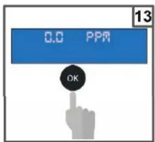
text_image
0.0 PPM OK
natural_image
Simple hourglass icon with '10 s' label and page number 14 (no text or symbols on the clock face)
text_image
15 Save and exittext_image
CAL Reference 26°C The unit will flash a temperature value Set the temperature value measured with the instrument Ex. 27°C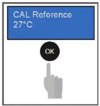
text_image
CAL Reference 27°C OKtext_image
HAYWARD We Build Better." Userware Password Log in List your password?Painel de controlo Vista inicial