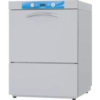
Mistral 415.3 - Dishwasher Elettrobar - Free user manual and instructions
Find the device manual for free Mistral 415.3 Elettrobar in PDF.

User questions about Mistral 415.3 Elettrobar
0 question about this device. Answer the ones you know or ask your own.
Ask a new question about this device
Download the instructions for your Dishwasher in PDF format for free! Find your manual Mistral 415.3 - Elettrobar and take your electronic device back in hand. On this page are published all the documents necessary for the use of your device. Mistral 415.3 by Elettrobar.
USER MANUAL Mistral 415.3 Elettrobar
natural_image
Diagram of a mechanical component with rollers and a downward arrow, no text or symbols present
natural_image
Diagram of a microplate with a downward arrow indicating a process or setup (no text or symbols present)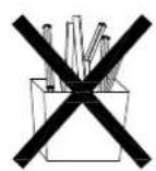

natural_image
Exterior view of a modern office building (no signage)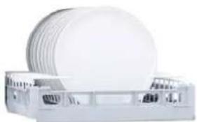
natural_image
White electronic device with a circular top and side ports, no visible text or symbols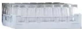
natural_image
Yellow industrial component with vertical fins, no visible text or symbolsFig.5
flowchart
graph TD
    A["OPEN"] --> B["ON"]
    B --> C["A"]
    C --> D["B"]
    D --> E["green fill"]
    E --> F["E"]
    F --> G["F"]
    G --> H["G"]
    H --> I["H"]
    style A fill:#f9f,stroke:#333
    style B fill:#ccf,stroke:#333
    style C fill:#cfc,stroke:#333
    style D fill:#fcc,stroke:#333
    style E fill:#cff,stroke:#333
    style F fill:#ffc,stroke:#333
    style G fill:#cfc,stroke:#333
    style H fill:#fcc,stroke:#333
    style I fill:#ffc,stroke:#333
text_image
orange orange End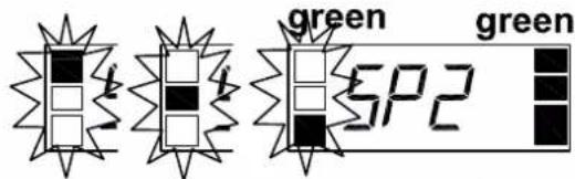
text_image
green SP2 greenFig.3
Fig.4
flowchart
graph TD
    A["Game A: F1, no"] --> B{Game B: YES, 1, 3, 2, 4}
    B --> C{Game C: F1, 1, 3, 2, 4}
    C --> D{Game D: green, LoAd, End, 5s}
    D --> E["End"]
flowchart
graph TD
    A["Step A: 3s. 1 3 2 4"] --> B["Step B: door"]
    B --> C["Step C: door"]
    C --> D["Step D: LMZ"]
    D --> E["Step E: door"]
    E --> F["Step F: b1 80"]
    F --> G["Step G: b2 60"]
    G --> H["Step H: b5 61"]
    H --> I["Step I: 1 3 4 1"]
    I --> J["Step J: door"]
text_image
3s. 1 3 2 4A
text_image
OFFB

text_image
CLOSEC

natural_image
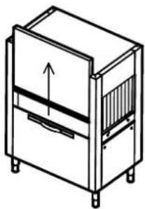
Isometric line drawing of a cabinet or rack unit with an upward arrow indicating motion or force (no text or symbols)D
natural_image
Two-panel black-and-white photo showing a hand pressing a component into a plastic container, labeled with numbers 1 and 2 (no text or symbols on the diagram itself)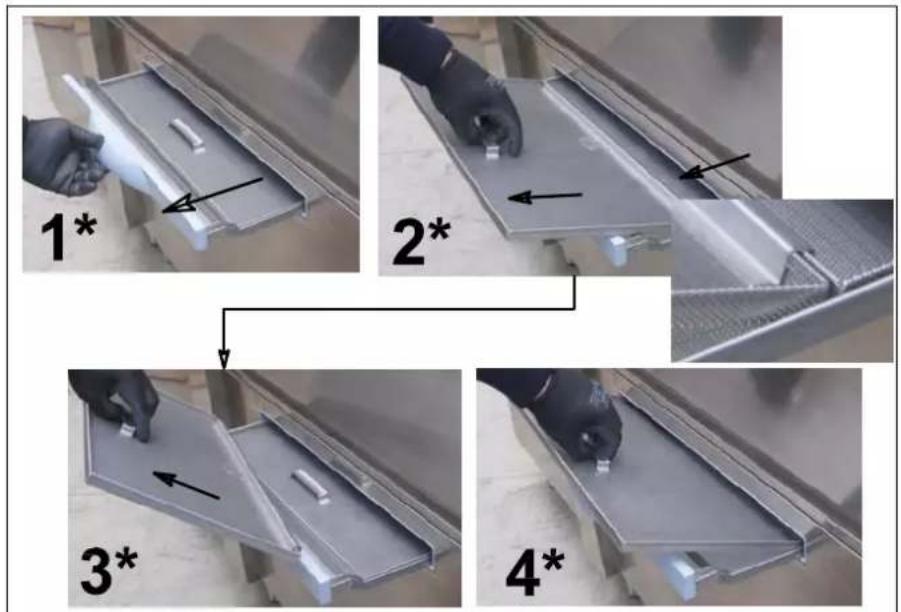
text_image
1* 2* 3* 4*E
natural_image
Close-up of a hand holding a cylindrical object with an arrow pointing upward, placed in a small bowl (no visible text or symbols)F

natural_image
Hand holding a white plastic stand with a bent handle, showing a black arrow pointing upward (no text or symbols visible)G
Fig.8
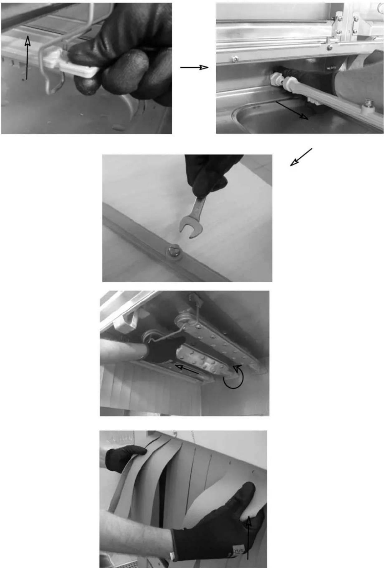
Fig.9
natural_image
Industrial machine with yellow plastic enclosures and a rack of white plastic panels, no visible text or symbolsFig.10
natural_image
Line drawing of a mechanical assembly with a bracket and stack of plates, no text or symbols presentFig.11
text_image
OFFA

natural_image
Pure technical line drawing of a mechanical assembly with no text, numbers, or symbolsB
text_image
Technical diagram showing a mechanical setup with labeled components and directional arrow, including a component marked 'x4'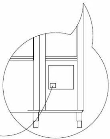
natural_image
Pure technical line drawing of a mechanical assembly without any text, numbers, or symbolsC
text_image
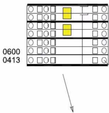
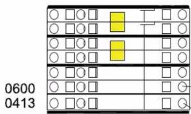
0600 0413
text_image
0600 0413D
Fig.12
natural_image
Simple curved line drawing resembling a teardrop or teardrop shape (no text or symbols)
natural_image
Simple line drawing of a cabinet with arrows indicating direction (no text or symbols)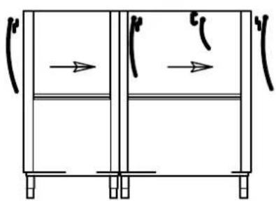
natural_image
Simple line drawing of a two-panel cabinet with arrows indicating flow direction (no text or symbols)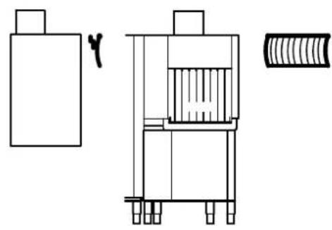
natural_image
Technical line drawing of a mechanical assembly with no visible text or symbols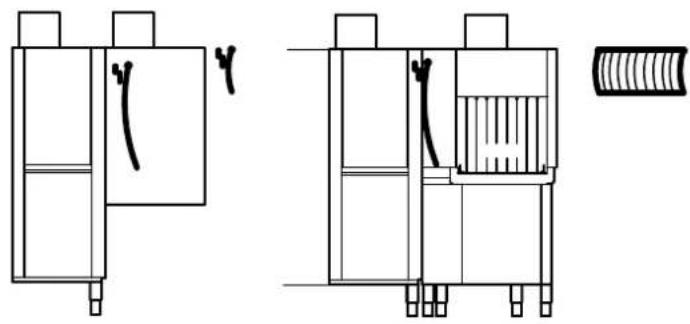
natural_image
Technical line drawing of a mechanical assembly with no visible text or symbolsDRYER
text_image
Diagram showing a mechanical or structural assembly with labeled components and directional arrows indicating flow or movement.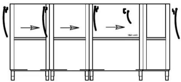
text_image
High speed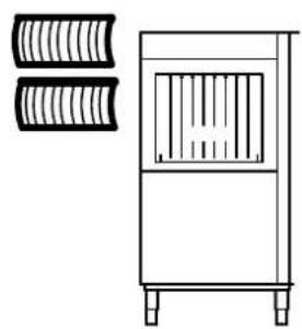
natural_image
Line drawing of a vertical air vent with two curved heat exchangers on the left side (no text or symbols)ANGLE PRE-WASH
DIN MODULE
Fig.13
INDEX
CAP 1 RISKS AND IMPORTANT WARNINGS....3
CAP 2 FOREWORD....6
CAP 3 HANDLING AND TRANSPORTING THE MACHINE....7
3.1 TRANSPORTATION AND PACKAGING 7
3.2 HANDLING....7
3.3 STORAGE 7
3.4 DIMENSIONS 7
CAP 4 INSTALLATION....7
4.1 HAZARD ZONES 7
4.2 IMPORTANT WARNINGS....9
4.3 ACOUSTIC PRESSURE LEVEL 9
4.4 UNPACKAGING AND POSITIONING....9
4.5 ENVIRONMENTAL CONDITIONS....10
CAP 5 INSTALLATION....10
5.1 ELECTRICAL CONNECTION....10
5.2 CONNECTION TO WATER SUPPLY 11
5.3 CONNECTION TO THE DRAIN NETWORK 12
5.3.1 Wash tank connection 12
5.3.2 Connection of drying drain and inlet module (optional) 12
5.4 CONNECTION OF STEAM HOSES (OPTIONAL) 13
5.5 CONNECTING THE LIMIT SWITCH 13
5.6 INSTALLATION OF DISPENSERS 14
5.8 COMMISSIONING....14
5.8.1 First boiler filling.... 14
5.8.2 Machine equipped with single boiler 14
5.8.3 Machine equipped with double boiler 15
5.9 CONTROLS 15
CAP 6 MACHINE DESCRIPTION....17
6.1 MACHINE DIAGRAM....17
6.3 SAFETY DEVICES....19
6.4 USE ACCORDING TO THE REGULATIONS 19
CAP 7 MACHINE USE 20
7.1 COMMAND DESCRIPTION....20
7.2 MACHINE START....20
7.3 HEATING....20
7.4 WASHINGTON....20
7.5 WASHINGTON PROGRAMME....20
7.6 STOP DEVICE 20
7.7 TEMPERATURE AND WORKING HOURS DISPLAY 21
7.8 LIMIT SWITCH DEVICE....21
7.9 REGULATIONS....21
7.9.1 temperatures 21
7.9.2 dispensers 22
7.10 USER MESSAGES....23
7.11 FUNCTION AND STATUS BARS 23
7.12 SELF-DIAGNOSIS 23
7.13 END OF WASHING OPERATIONS 25
7.14 POSITIONING THE DISHES....25
CAP 8 MAINTENANCE....26
UK
DISHWASHER INSTRUCTIONS MANUAL
8.1 GENERAL RULES 26
8.2 PERIODICAL MAINTENANCE 27
CAP 9 DISPOSAL 28
CAP 10 ENVIRONMENT....28
Read the instruction manual carefully before starting the machine. It contains important information regarding safe installation, use and maintenance. Failure to observe the instructions in the enclosed documentation may compromise appliance safety and immediately voids the warranty.

Cap 1 RISKS AND IMPORTANT WARNINGS
- This appliance is intended solely for the use for which it was designed. Any other use is deemed improper and therefore hazardous.
- The specialised personnel responsible for installing the appliance must adequately instruct the user on its operation and any relevant safety measures, also providing practical demonstrations.
- Keep the machine in perfect working order and always use the various protection devices it is fitted with; ensuring regular maintenance is carried out by professionally qualified personnel. In particular, make sure all the safety devices are periodically inspected by them.
- In case of a fault or malfunction, switch the appliance off, disconnect the power supply, shut off the water and do not attempt to carry out any repairs or intervention directly; request the assistance of an authorised repair technician.
- Only the manufacturer or an authorised service centre with qualified personnel may work on the machine, even in case of malfunction, only using original spare parts.
- Failure to comply with the above may compromise the safety of the appliance.
- Always disconnect or isolate the machine from the power and water supplies before servicing, repairs or cleaning, turning off the system switch.
- NEVER use water to extinguish fires on the electrical parts. Use a powder fire extinguisher.
- The machine must NOT be used by untrained persons.
- The appliance CANNOT be used by children and by persons with reduced physical, sensory or mental capabilities, or lacking in experience and the necessary expertise.
• Children must NOT play with the appliance. - Cleaning and maintenance intended to be carried out by the user must NOT be done by children.
- The machine must NOT remain switched on when not in use.
- Always turn the machine off at the wall switch when not in use.
- Shut off the water supply whenever the machine is not in use.
- In case of leaks of water or liquids, immediately switch the machine off and shut off the water supply.
-
If an appliance of this type is no longer going to be used, make it inoperative by removing the power cable, after having disconnected it from the mains.
-
If the machine is not fitted with a plug or other means of complete disconnection with separation of all the contacts, these disconnection devices must be incorporated into the power mains, in compliance with the installation rules.
- If the power cable is damaged, it must be replaced by the manufacturer or an authorised technical assistance service, or in any case by a person with similar qualifications, to prevent any risk.
- The screw on the appliance marked with the IEC 60417 standard symbol 5021 is the equipotential connection.
- NEVER open the doors of the machine quickly during operation. Wait at least 15 seconds after the motors have stopped.
- When opening the doors, make sure they are properly attached to their supports.
- Check that the direction of rotation is as marked on the central moving part. Otherwise contact qualified personnel to reverse the direction of rotation of the whole machine
- Should the rack conveyor system stop due to the safety device, remove the obstacle that caused the blockage before restoring operation. To retrieve any items that have fallen inside the machine, stop the machine and switch it off.
- Do not remove the basket before it has completely exited the machine.
- To avoid the risk of becoming entangled and dragged keep away from moving parts if wearing dangling jewellery or very large or wide-sleeved garments.
- NEVER use the machine without the protection devices arranged by the manufacturer.
- Make sure all items being washed are dishwasher safe.
- NEVER use the machine to wash objects of type, shape or material not guaranteed as machine washable or not perfectly intact.
- NEVER use the appliance or any of its parts as steps or a support for people, property or animals.
- Do not use the machine as support surface for any objects and/or tools.
- NEVER overload the open door of front-loading machines; it is designed to only support the basket loaded with dishes.
- NEVER place bare hands in the washing solutions. If water containing detergent accidentally comes into contact with eyes, rinse with plenty of clean water and seek medical advice.
- When inserting baskets into the wash chamber, it is OBLIGATORY to wear latex, or rubber, long-sleeved gloves.
- NEVER overturn the machine after it has been installed.
- Do not install the dishwasher near heat sources over 50^ .
- NEVER leave the dishwasher exposed to the weather (rain, direct sunlight, etc.)
- The dishwasher must NOT be installed outdoors without adequate cover.
- Do not obstruct the air inlet or outlet grilles.
- Do not operate the machine without filters.
- Never start a wash program without the overflow, if foreseen.
- NEVER place magnetic objects near the machine.
- Before connecting the appliance, make sure the details on the data plate match those of the mains power and water.
- Check that the electrical capacity of the system is adequate for the maximum power absorbed by the appliance. If in doubt, contact a qualified person who must check that the cross-section of the system cables is suitable for the power absorbed by the appliance.
- The incoming power supply cables (not provided) to the main switch must be indicated with the appropriate danger warnings.
- The appliance power supply cable must be H07RN-F type.
- The installer technician must check the efficiency of the “earth” as required by the applicable safety standards. This fundamental safety requirement must be respected; if in doubt, request a thorough inspection of the entire system by professionally qualified personnel.
- At the end of testing, the installer technician must issue a written declaration regarding correct installation and testing according to the applicable regulations and highest standards.
- DO NOT modify the protection devices. Remove them only if the machine is stopped and disconnected from the power supply; reinstate them before reconnecting it to the power supply.
- After disconnecting the power supply, only qualified personnel may access the control panel.
- DO NOT change the position of or tamper with the machine's parts, as this could compromise its safety.
- DO NOT use dispensing devices or other devices not prescribed by the manufacturer, which may alter the machine's safety or operating characteristics.
- Noise pressure level according to EN ISO 4871
○ LpA Max = 68.0db Kpa=2.5db for versions without drying
○ LpA Max = 69.5db Kpa=2.5db for versions with drying
• Max inlet water temperature: 65°C
- Max inlet water pressure: 4bar (400kPa)
- Appliance designed for permanent connection to the water supply
- For cleaning operations, carefully follow the instructions provided in the manufacturer's handbook.
- The appliance must NOT be cleaned with steam or water jets.
- Only use anti-foaming detergents specific for dishwashers, in the doses recommended by the manufacturer according to the water hardness and tank capacity.
- Never use acidic or corrosive products to clean the machine or to wash
dishes.
- Never use products containing chlorides in concentrations above 50 ppm as a dishwasher detergent or to clean the machine.
- Never use steel wool pads, steel brushes or shavings to clean the stainless steel.
- In order to protect the environment, avoid the use of corrosive or pollutant products and do not exceed the recommended doses.
- Personnel in charge of handling the dishes must strictly follow the applicable hygiene regulations after the wash.
- Remember that the machine must NEVER be operated without the special protection curtains: at entry, exit, and intermediate positions.
- Max unloading height
- On the ground in versions with overflow
○ Maximum height 1 m in versions with drain pump
Normal operating conditions
Ambient temperature : 40°Cmax /4°Cmin (average 30°C)
Altitude : up to 2000 metres
Relative humidity : Max 30% at 40°C / max 90% at 20°C
Cap 2 FOREWORD
Warnings:
Carefully store all the documents near the appliance. Hand them to the technicians and workers charge of use and make sure they are kept well preserved over time, at a safe location, ideally with copies for frequent consultation.
The operator must read, understand and learn the present manual before carrying out any operation on the device.
This piece of equipment is destined exclusively to the professional washing of tableware for large numbers of people. Therefore, its use and maintenance are only to be carried out by well-trained personnel, committed to following the manufacturer's instructions.
Warranty:
The manufacturer declines all responsibility and warranty for damages to things or persons derived from failure to follow the instructions provided herein or from improper use of the machine.
Failure to follow the indications contained in the attached documents may compromise the safety of the device and cause the warranty to be immediately annulled.
Installation and repairs carried out by unauthorised technicians, or the use of non-original spare parts, will cause the warranty to be immediately annulled.
Cap 3 HANDLING AND TRANSPORTING THE MACHINE

natural_image
Line drawing of a semi-truck with front grille and side panel (no text or symbols)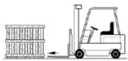
3.1 Transportation and packaging
The machines can be transported in two manners:
- on lorries
- in containers
Both situations require the same kind of packaging.
3.2 Handling
- The machines must be handled with care, using a forklift truck or a hand pallet truck.
- The hoisting points are marked on the machine by adhesive labels.

- During transportation, it is forbidden to remain near the machine, as it may tilt and cause serious harm to persons nearby.
- Accidents may involve impact, entanglement, and trapping by the machine during handling and storage of the machine itself.
3.3 Storage
Storage methods for materials must include pallet, containers, conveyor belts, vehicles, lifting equipment and devices suitable for the prevention of damages caused by vibration, impact, abrasion, corrosion, temperature or any other condition that may occur. The parts stored must be periodically inspected for deterioration.
Storage:
Transportation and deposit: between -10^ C and 55^ C, with peaks of up to 70^ C (max 24 hours)
3.4 Dimensions
The machines of the rack conveyor line are available in various models, whose layouts are attached to this document, including the dimensions of each machine.
Cap 4 INSTALLATION
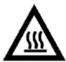
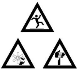
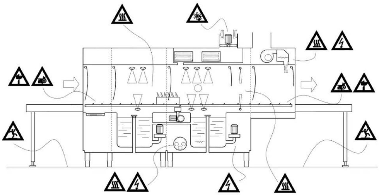
4.1 Hazard zones
Definition of hazard zones and how (see fig. on next page) they are indicated, plus a general description of the protection measures adopted.

Risk of entanglement and dragging
- On the conveyor
Thermal hazard
- on the doors accessing the wash / rinse section
- on the drying chamber walls.
- on the boiler during machine installation and maintenance.
DISHWASHER INSTRUCTIONS MANUAL
- Inside the machine for removal of the wash tank overflow.
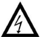
Electrical shock hazard
- electrical control panel
- electropumps
- fan
- electrical elements
text_image
Warning sign with three triangular symbols: falling person, cross symbol, and hand gestureSlippery floor hazard
- On floor wet from splashes and steam condensation
Shearing hazard
- on the fan of the extraction unit
- inside the machine on sheet metal sheet and sharp profiles
The machine is equipped with casings that limit access to the interior and to moving parts; these are fixed to the machine with screws.
flowchart
graph TD
    A["Start"] --> B["Process Unit"]
    B --> C{Safety Warning}
    C -->|Yes| D["Control Unit"]
    C -->|No| E["Warning Device"]
    D --> F["Storage Tank"]
    F --> G["Refrigeration Tank"]
    G --> H["Pressure Sensor"]
    H --> I["End"]
4.2 Important warnings
Before carrying out any operations inside the wash chamber with the machine switched off which require removal of the tank filters and/or the wash and rinse arms, wear protective gloves with a blade cut-resistance of no lower than 3 in accordance with standard EN388.
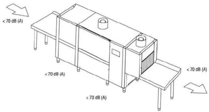
4.3 Acoustic pressure level
text_image
< 70 dB (A) < 70 dB (A) < 70 dB (A) < 70 dB (A)4.4 Unpackaging and positioning
When the machine is received, open the packaging and check the machine and its accessories for damage occurred during transportation. If any damages are detected, immediately report to the transportation company and do not proceed with installation: seek the assistance of qualified, authorised personnel.
The manufacturer cannot be held responsible for any damage occurred during transportation.
Packaging elements (plastic bags, Styrofoam, strips of wood, nails etc) must be kept away from the reach of children, as they are potentially hazardous.
natural_image
Illustration of a hand holding a tool with a device attached (no text or symbols)Position the machine according to the indications supplied by the general installation layout, supplied separately, making sure its position is correct regarding maintenance needs.
Screw the feet to the supports and place the machine in its proper position. Adjust the height of the feet to level the machine. As these machines are long, use a spirit level.
Warning:
While positioning the machine, do not drag it on the floor, as this may damage its structure.
The floor must be dimensioned taking into consideration the overall weight of the machine. The floor must be levelled.
4.5 Environmental conditions
• Environmental temperature: 40°C max/4°C min (average: 30°C)
• Altitude: up to 2,000 metres
• Relative humidity: Max 30% at 40°C/max 90% at 20°C
Cap 5 INSTALLATION
5.1 Electrical connection
text_image
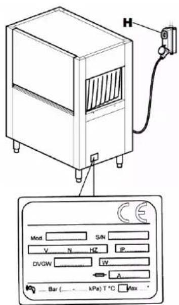
H Mod. S/N V. N. HZ IP. DVGW W A Bar ( kPa) T °C Max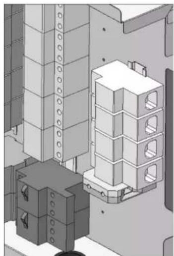
natural_image
Isometric view of a mechanical assembly with stacked housing and mounting brackets (no text or symbols visible)- Warning! Installation must be carried out only by specialised technicians!
- Before connecting the equipment, make sure that both the voltage and frequency of the mains power supply correspond to those indicated on the data plate affixed to the side panel of the machine.
- To connect the machine to the mains power supply, use only H07RN-F type power supply cables with a conductor cross-section appropriate for the maximum absorption indicated on the data plate and as indicated in the table below.
• Take care when laying out the cable to observe the minimum bend radius indicated by the cable manufacturer.
| H07RN-F | ||
| Current (A) | Cross-section (mm2) | Maximum length (mm) |
| 40 | 10 | 5000 |
| 50 | 16 | |
| 63 | 16 | |
| 80 | 25 | |
| 100 | 35 | |
| 125 | 50 | |
- The machine must be connected to the power supply by means of a type "C" dedicated automatic omnipolar switch in compliance with safety regulations in force, or alternatively with a disconnect switch having fuses with 3 mm minimum opening distance between contacts. The above-mentioned switch, not supplied with the machine, must wall-mounted at an easily accessible point, at a height between 0.6 m and 1.70 m.
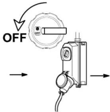
- Before connecting the machine to the power supply, make sure the power is switched off at the mains.
- Remove the front panel and the cover of the electrical board by removing the screws.
- Feed the power cable through the cable gland on the back of the machine.
- Connect the cable to the terminals on the board, as indicated in the wiring diagram attached.
- If the Neutral and Earth cables are incorrectly connected, this can result in irreversible damage to the machine, and the warranty may be invalidated!
- Check that the cables on the contactors, thermal protections etc. are properly tightened, as the screws may have worked loose during transportation.
- Refit the front cover panel and the control panel using the screws provided.
- The power supply cable must not be stretched or crushed during normal operation or routine maintenance.
- The appliance must also be connected to an equipotential system with a screw marked with the symbol.
- The equipotential cable must have a cross section of 10 ~mm^2 .

Do not use multi-sockets, adapters, cables of an inadequate cross-section or type or with extensions not conforming to established electrical installation regulations.
natural_image
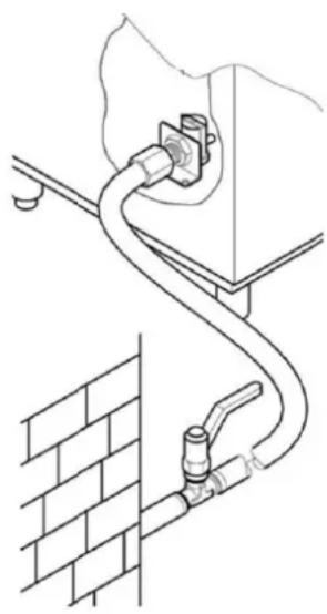
Technical line drawing of a pipe installation with a valve and brick wall (no text or symbols)5.2 Connection to water supply
Prepare the installation site according to the installation diagram attached.
Before connecting the appliance, make sure that there is a gate valve installed between the mains water supply and the machine, allowing the water supply to be shut off in case of need or when carrying out repairs. In addition, make sure that the water supply flow rate is no lower than 20 l/min.
Warning!
- Make sure that the temperature and pressure of the mains water supply are within the range of pressure and temperature values indicated on the technical data plate. If they are not, it will not be possible to achieve suitable water flow rates and temperatures for proper rinsing.
If the local mains water is harder than the value indicated on the data plate, we recommend installation of a water softener upline of the machine's solenoid inlet valve.
If the water has a very high residual concentration of high conductivity minerals, we recommend installation of a demineralisation system calibrated to achieve residual hardness as indicated in the table below.
| Characteristics | Min | Max | ||
| Hardness | French degrees | f | 5 | 10 |
| German degrees | °dH | 4 | 7.5 | |
| English degrees | °e | 5 | 9.5 | |
| Mineral residues (TDS) | Parts per million (20°C) | ppm | 70 | |
| mg/l | 70 | |||
Warning!
- Machines intended for use with desalinated water or in any case with water having a high concentration of sodium chloride, must be expressly ordered, as their construction requires the use of specific materials.
5.3 Connection to the drain network
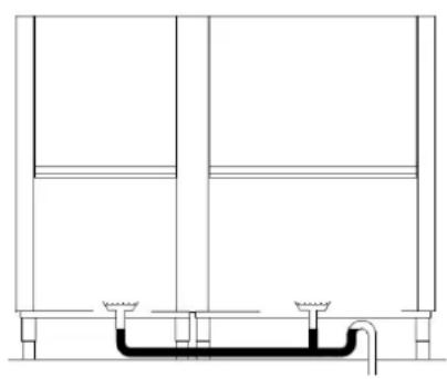
The machine is supplied complete with corrugated drain hoses and connectors for each tank to be used in the event that the drainage water is to be channelled into a single drain outlet equipped with a syphon as described in the following paragraph.
These drain hoses are not recommended for use in the event of direct drainage into a sump.
5.3.1 Wash tank connection
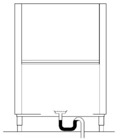
natural_image
Pure technical line drawing of a mechanical component or tank with no text, numbers, or symbols- Rack conveyor dishwashers operate continuously, which means they require particularly efficient and functional drainage systems.
- For the position of drains on each tank and the exact dimensions, refer to the installation diagram enclosed with each machine.
- Connect the machine's drains to the mains drainage using hoses designed to withstand a continuous temperature of 70^ C, using the connectors supplied if necessary.
- The drainage system must always include a siphon, even in the case of direct drainage into a sump as illustrated in the figure
- In the case of multiple wash tanks, they may all be connected to a single siphon
- The height from the ground of the siphon "H" must not exceed the height B of the drain pipe as illustrated in the figure.
natural_image
Pure technical line drawing of a mechanical or architectural component without any text, numbers, or symbols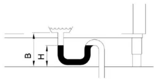
text_image
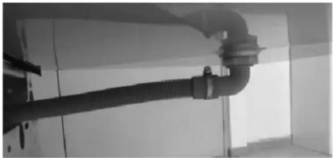
B H5.3.2 Connection of drying drain and inlet module (optional)
When present, the drying drain (see photo) and inlet module must also be connected to the mains drainage using the corrugated hose supplied with the machine
Warning!
In some versions the drying chamber drain is already connected to the wash tank.
natural_image
Close-up of a pipe fitting with coiled tubing, mounted on a wall (no visible text or symbols)5.4 Connection of steam hoses (optional)
The machine vents steam during operation and it is therefore advisable to install a forced air extraction hood above it (1500-3000 m ^3 /h)
Alternatively, on request the machine can be supplied ready-fitted with a steam extraction or recovery system.
In the latter case, steam can also be channelled directly outside the installation space by means of a flue consisting of suitable stainless steel ducting with a diameter of 250 mm.
Warning!
- The drying module flue is designed to close the motor housing and must not be connected to any hose.
- Do not use fully demineralised water in machines with a recuperator fitted with heat recovery batteries with copper pipes. In this case, request the version with batteries with stainless steel pipes.
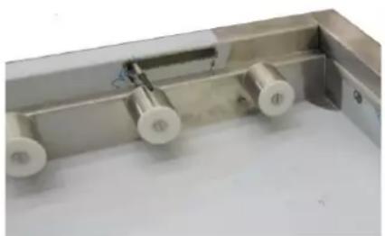
5.5 Connecting the limit switch
natural_image
Close-up of a metallic mechanical component with three white cylindrical pins and a blue cable, no visible text or symbols.The machine MUST be fitted with a limit switch before use.
- The limit switch must be installed on the outfeed table.
- The switch must be mechanically fixed to the machine in such a way as to guarantee its operation
- We recommend using a limit switch of the type with lever activation with washer or spring, to increase the contact surface and reduce the effect of mechanical contrast.
- Checks must be carried out to verify proper functioning of the limit switch with all the baskets in use on site.
- It must have a protection level of at least IP55
- The limit switch must be in positive mode (contact normally closed)
- It must have a minimum rated capacity of 240V 1.5A
- Recommended mechanical duration 10,000 K cycles.

natural_image
Close-up of a blue industrial sensor device with threaded connector and attached cable (no visible text or symbols)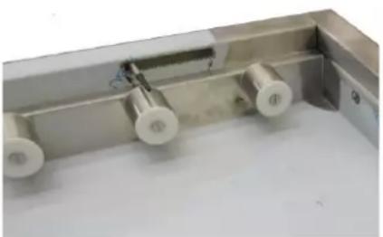
natural_image
Close-up of a metallic mechanical component with cylindrical and circular features (no visible text or symbols)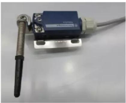
natural_image
Close-up of a blue industrial sensor device with attached cable and metal connector (no visible text or symbols)5.6 Installation of dispensers
The machine is equipped with specific outputs for rinse aid and detergent dosing devices. Connect the dosing devices as shown in the wiring diagram to ensure the correct operation of the machine.
The rinse aid and detergent must be dosed by the automatic dispensers.
The amount of both of these products is established by the installation technician based on local water hardness, and the technician also calibrates the dispensers themselves.
For the initial filling of the dosing circuit and the relative settings, see the "Settings" paragraph.
- The level of liquids in the containers must never be allowed to reach empty.
- The dispensers must never be filled with corrosive or contaminated products.
- Chlorine-based products must not be used under any circumstances, as they cause the formation of chloride, which in concentrations above 50 ppm can lead to corrosion
- It is not advisable to dispense the products manually.
- For any other installation, refer to the wiring and installation diagrams enclosed
- The machine cannot be fitted with multi-voltage dosing devices and/or dosing devices with absorption higher than 5A per output.
If you wish to use this type of dosing device, it must be connected to an external 16A relay
WARNING!
- The use of detergents containing chlorides in a concentration exceeding 50 ppm can lead to corrosion of the machine's stainless steel structure.
5.7 Installation of protection curtains
The machine is equipped with protection curtains to separate the various sections of the machine.
For the assembly diagram, see figure 12.
5.8 COMMISSIONING
5.8.1 First boiler filling
The boiler is empty at the time of initial machine installation, so the electrical elements are disconnected in order to prevent idle operation which could result in damage.
To activate the elements, follow the first boiler charging procedure as described below.
5.8.2 Machine equipped with single boiler
Reference: Figures 2 and 6
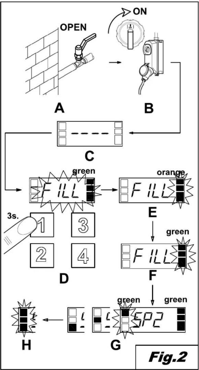
- Open the gate valve of the water supply system (Fig. 2/A)
• Supply the machine with power by switching on the main switch (Fig. 2/B) - The display will show 4 horizontal bars (Fig. 2/C)
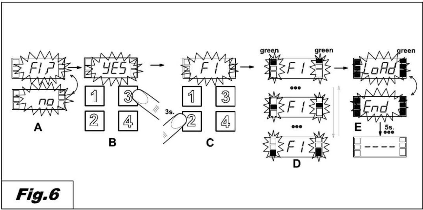
- Press the line button (1) to switch the machine on. (Fig. 2/D)
- The display will show the alternating message "FI?" "no" (Fig. 6/A)
- Press button (3) to select "yES" (Fig. 6/A)
• To confirm, press button (2). (Fig. 6/C) - The machine will automatically start loading the boiler, and the display will show the message "FI" (Fig. 6/D)
- When the display shows the alternating messages “LoAd” “End”, it means the loading phase is concluded, and the machine is ready to be switched on. (Fig. 6/E)
5.8.3 Machine equipped with double boiler
Reference figure 12
For versions equipped with a second boiler, after following the instructions given in the paragraph above, proceed as follows to activate the heating of the elements.
- Disconnect the power supply using the main switch (fig.12/A)
- Remove the panel under the rinse section (fig.12/B) to access the electrical control panel
- Remove the cover of the control panel and access the terminal board (fig.12/C)
- Activate the electrical element by connecting the two terminals indicated in figure 12/D with the wire supplied
Refit the electrical control panel cover and the panel.
5.9 Controls
- Make sure that the level of water in the washing tank, once filled, is 1-2 cm below the overflow level.
- Make sure that the temperature of the washing and rinsing tank is in accordance with the settings.
- Check the dispensers for proper function.
- Make sure the rinsing economiser is working well: it must start dispensing hot water as soon as a basket arrives beneath the rinsing jets, and make the hot water flow stop when the basket moves away.
- Make sure the limit switch is working. The switch must block the functioning of the advancement motor and of the pump whenever a basket reaches the end of the plane. Once the basket is removed, the functioning must resume.
- Check the rotation direction of the pumps. If they are turning in the opposite direction, invert the two phases of the power supply cable.
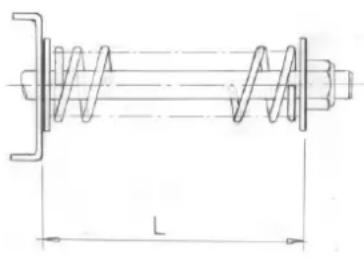
natural_image
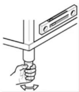
Technical line drawing of a mechanical spring assembly with dimension L (no text or symbols)- Check the regulation of the mechanical safety system of the conveyor, which must be adjusted taking into account the overall length of the machine and of the output tables measured by themselves.
A full load of baskets full of plates should not block the advancement of the conveyor.
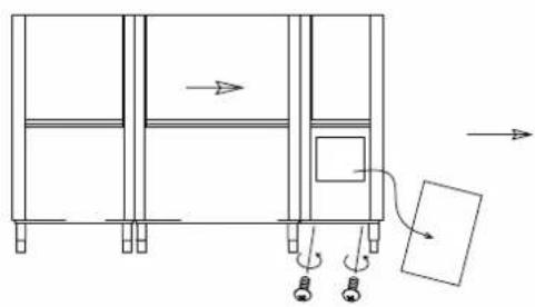
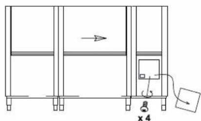
To make the regulation, turn the screw on the bracket that supports the conveying motion unit.
The advised L length must range from 60 to 75 mm (see figure).
Please contact your assistance centre for complex applications.
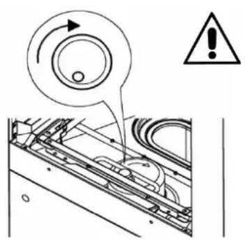
text_image
Technical diagram showing a device with a warning symbol and circular component, including an arrow and exclamation mark.- Make sure that the rotation direction corresponds to the figure and to the central motion of the conveyor.
WARNING: The mechanical safety will not work efficiently if the rotation direction is incorrect.
DISHWASHER INSTRUCTIONS MANUAL
- Only for versions equipped with pressure regulator with manometer, check the manometer during rinsing. If necessary, adjust the pressure regulator and set the value as indicated in the table:
| Version | Litres/hourBaskets/hour | bar | 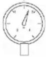 |
| No pre-wash | 160 | 0.6 | |
| With pre-wash | 270 | 0.7 |

Failure to carry out these checks will automatically annul the warranty.
END OF INSTALLATION
- The installation technician must inform the manufacturer in case of functioning and/or safety anomalies observed during the initial testing.
- The machine can only be used once installation is complete.
- The technician must issue a declaration of work carried out according to the rules of the trade and to the laws in force.
Cap 6 MACHINE DESCRIPTION
6.1 Machine diagram
Diagram of machine with single rinsing
flowchart
graph TD
    A["Material Input"] --> B["Stage 1"]
    B --> C["Stage 2"]
    C --> D["Stage 3"]
    D --> E["Stage 4"]
    E --> F["Stage 5"]
    F --> G["Stage 6"]
    G --> H["Stage 7"]
    H --> I["Stage 8"]
    I --> J["Stage 9"]
    J --> K["Stage 10"]
    K --> L["Output"]
    style A fill:#f9f,stroke:#333
    style B fill:#ccf,stroke:#333
    style C fill:#cfc,stroke:#333
    style D fill:#fcc,stroke:#333
    style E fill:#cff,stroke:#333
    style F fill:#ffc,stroke:#333
    style G fill:#cfc,stroke:#333
    style H fill:#fcc,stroke:#333
    style I fill:#ffc,stroke:#333
    style J fill:#cfc,stroke:#333
    style K fill:#fcc,stroke:#333
    style L fill:#ffc,stroke:#333
Diagram of machine with multiple rinsing
flowchart
graph TD
    A["Top Tank"] --> B["1 Tank"]
    B --> C["2 Valve"]
    C --> D["3 Valve"]
    D --> E["4 Valve"]
    E --> F["5 Valve"]
    F --> G["6 Valve"]
    G --> H["Bottom Tank"]
    H --> I["8 Valve"]
    I --> J["9 Valve"]
    J --> K["10 Valve"]
    K --> L["11 Valve"]
    L --> M["13 Tank"]
    style A fill:#f9f,stroke:#333
    style H fill:#ccf,stroke:#333
Diagram of machine with two-stage rinsing
flowchart
graph TD
    A["Top Tank"] --> B["1 Tank"]
    B --> C["2 Valve"]
    C --> D["3 Tank"]
    D --> E["4 Valve"]
    E --> F["5 Valve"]
    F --> G["6 Valve"]
    G --> H["Bottom Tank"]
    H --> I["7 Pipe"]
    I --> J["8 Valve"]
    J --> K["9 Valve"]
    K --> L["10 Valve"]
    L --> M["11 Valve"]
    M --> N["12 Valve"]
    style A fill:#f9f,stroke:#333
    style H fill:#f9f,stroke:#333
DISHWASHER INSTRUCTIONS MANUAL
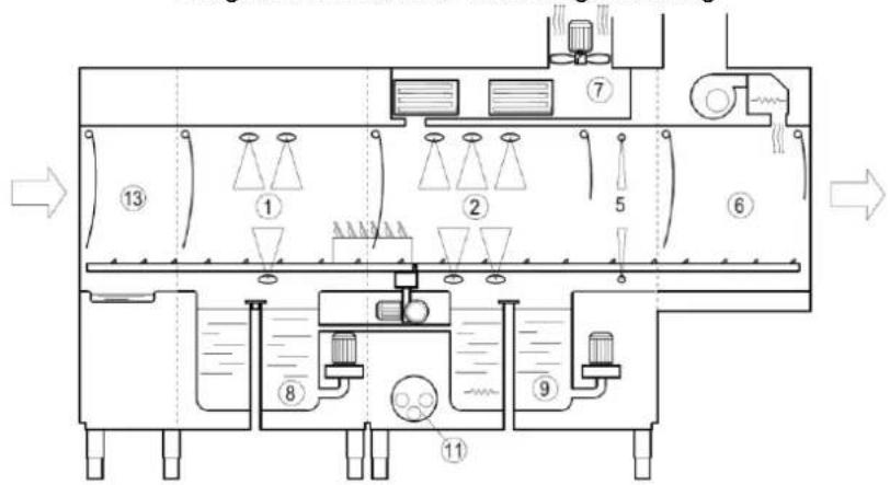
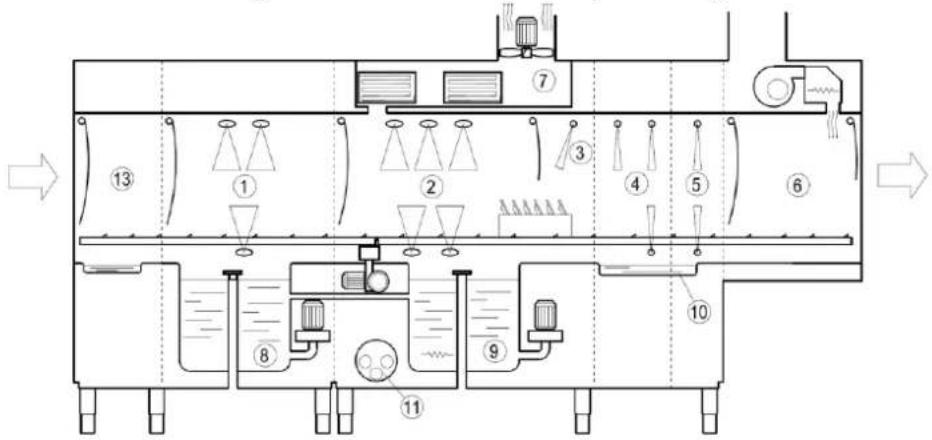
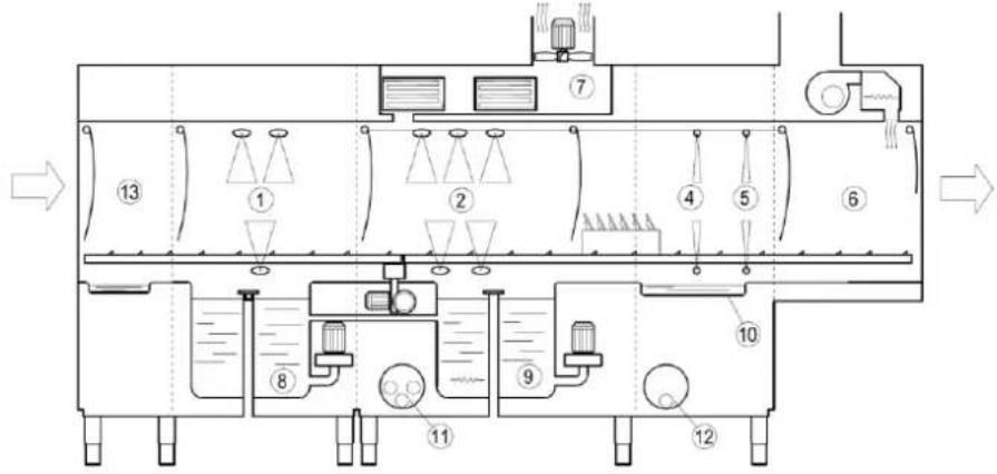
1 Pre-wash chamber 5 Final rinse chamber 9 Wash tank
2 Wash chamber 6 Drying chamber 10 Rinse tank
3 Pre-rinse chamber 7 Steam extraction and recovery zone 11 Boiler
4 First rinse chamber 8 Pre-wash tank 12 Second boiler
13 Entry hood
Conveying belt washing machines are manufactured with high-quality materials: AISI 304 stainless steel for the washing tanks and stainless steel for the remaining parts.
• In pre-wash section 1, the dishes are given an initial brief clean to remove larger food particles.
- In wash section 2, the dishes are actually washed.
- In sections 3, 4, 5 the dishes are rinsed.
• In section 6, the dishes are dried.
- In section 7, steam is extracted or heat is recovered.
- The baskets are automatically conveyed through the sections by means of a lateral conveyor.

6.2 Dangerous points
A dangerous point or dangerous area of the machine is an area in which accidents may occur in case of failure to follow the instructions.
- If the conveyor stops during regular functioning, press the line button. Only restart the machine once the cause of the blockage has been identified and removed.
- It is forbidden and very dangerous to access the internal part of the machine from the entrance or exit of the conveyor when the machine is on and in motion.
- It is forbidden and very dangerous to make repairs to the conveying system and to the electric users when the machine is working.
- It is forbidden to use the machine without the surveillance of an operator.
- Do not submerge your hands in the water in the tanks.
- When inserting baskets into the wash chamber, it is obligatory to wear latex, or rubber, long-sleeved gloves.
- It is forbidden to access the switch to deactivate or activate the machine with wet hands.
- It is absolutely forbidden to access the internal part of the electric box.
6.3 Safety devices
- On the doors there are magnetic switches that interrupt pre-wash, wash, rinse and basket conveying, when opened.
- Protection against unexpected start-up. If the machine accidentally stops due to lack of electricity, it will not resume automatically when the power returns.
- Thermal protections for electro-pumps and motors, guaranteeing their integrity in case of short-circuit and overload.
- Magneto-thermal protections or fuses for each heating element, protecting elements from the dangers of short-circuits and overload.
- Boiler safety thermostat. In case of malfunctioning of a thermostat for temperature control, a second safety thermostat will intervene and interrupt the functioning of heating elements.
- Safety microswitch on the conveyor. If the conveying stops due to accidental causes, the microswitch installed near the support of the motor reducer will interrupt the conveying function.
- Safety door stop. When the doors are opened, the hooks prevent them from falling if a spring should break.
- Low-voltage commands.
6.4 Use according to the regulations
- Conveying machines are expressly designed to wash dishes, glasses, cups, flatware and similar items together with the basket in which they are placed. Any other use is considered to be not in accordance with the regulations.
- It is imperative to respect the manufacturer's safety, use and maintenance regulations.
- It is imperative to respect the suitable regulations to prevent accidents, and further acknowledged safety technique regulations.
- The machine must only be used by personnel suitably trained to avoid hazards.
- The machine must only be used with original manufacturer's accessories and spare parts.
Cap 7 MACHINE USE
7.1 Command description
With reference to Fig. 1
| 1 | ON/OFF LINE BUTTON | 5 | INFORMATION DISPLAY |
| 2 | START/STOP BUTTON | 6 | FUNCTION BAR (LED) |
| 3 | PROGRAMME SELECTION BUTTON | 7 | ALARM BAR (LED) |
| 4 | SPECIAL PROGRAMME SELECTION BUTTON |
7.2 Machine start
Reference to Figure 2
- Open the gate valve of the water supply system (Fig. 2/A)
• Supply the machine with power by switching on the main switch (Fig. 2/B) - The display will show 4 horizontal bars (Fig. 2/C)
- Press the line button (1) to switch the machine on. (Fig. 2/D)
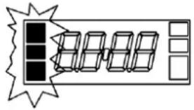
- The display will flash the message "FILL" and the machine will start loading water (Fig. 2/E).
- Once the proper level has been reached, the display will show the default message "SP2". (Fig. 2/G)
7.3 Heating
Reference to Figure 2
- Once the loading is finished, the machine will automatically start heating.
- During heating, the LED function bar (6) is orange (Fig. 2/G).
- As soon as the pre-set temperature is reached, the LED function bar (6) will turn green and fixed. (Fig. 2/H)
7.4 Washing
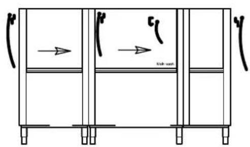
Reference to figure 4
- To start washing, simply insert a basket at the entrance of the machine until it is hooked by the basket conveying system.
- The LED function bar (6) will then start moving.
- During washing, the display will show the washing programme being used.
7.5 Washing programme
Use the keyboard to select the following programmes:
standard programmes selected using button (4)
- SP1 "Hight capacity ", to wash dishes with light, fresh dirt.
- SP2 "General purpose", programme for general use.
programmes selected using button (3)
- AP1 "Prolonged contact" ensures a longer washing time, in accordance to regulation DIN 10534
- AP2 "Glass" programme, specific for the washing of glasses.
It is only possible to select a different programme during washing after pressing button (2).
7.6 Stop device
The machine is equipped with a ON/OFF line button (1) on the control board, and its use causes the immediate stop of all moving parts and of the washing programme.
It is possible to install additional optional stop devices near the entrance and the exit of the baskets.
7.7 Temperature and working hours display
It is possible to visualise washing and rinsing temperatures at any moment.
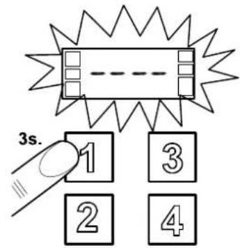
Simply keep button (2) pressed for a few seconds.
The display will show, in sequence, the washing temperature "t", the rinsing temperature "b", and the machine hours of work "Hr".
The message is displayed twice.
7.8 Limit switch device
The machine must work with a limit switch installed on the exit plane of the baskets (see installation chapter).
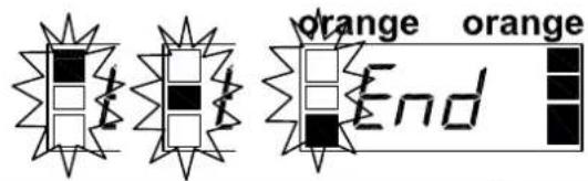
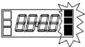
The display will show the message “End” when a basket exiting the machine reaches the end of the plane, and the conveyor stops until the basket is removed (Fig. 3).
Simply remove the basket from the end of the plane to restart the machine completely.
If the basket is not removed within a few minutes, the machine will switch off, in a succession, the rinsing area, the washing area, the pre-wash area and, finally, the drying area, when installed.
7.9 Regulations
It is possible to regulate the temperature and the dispensing times.
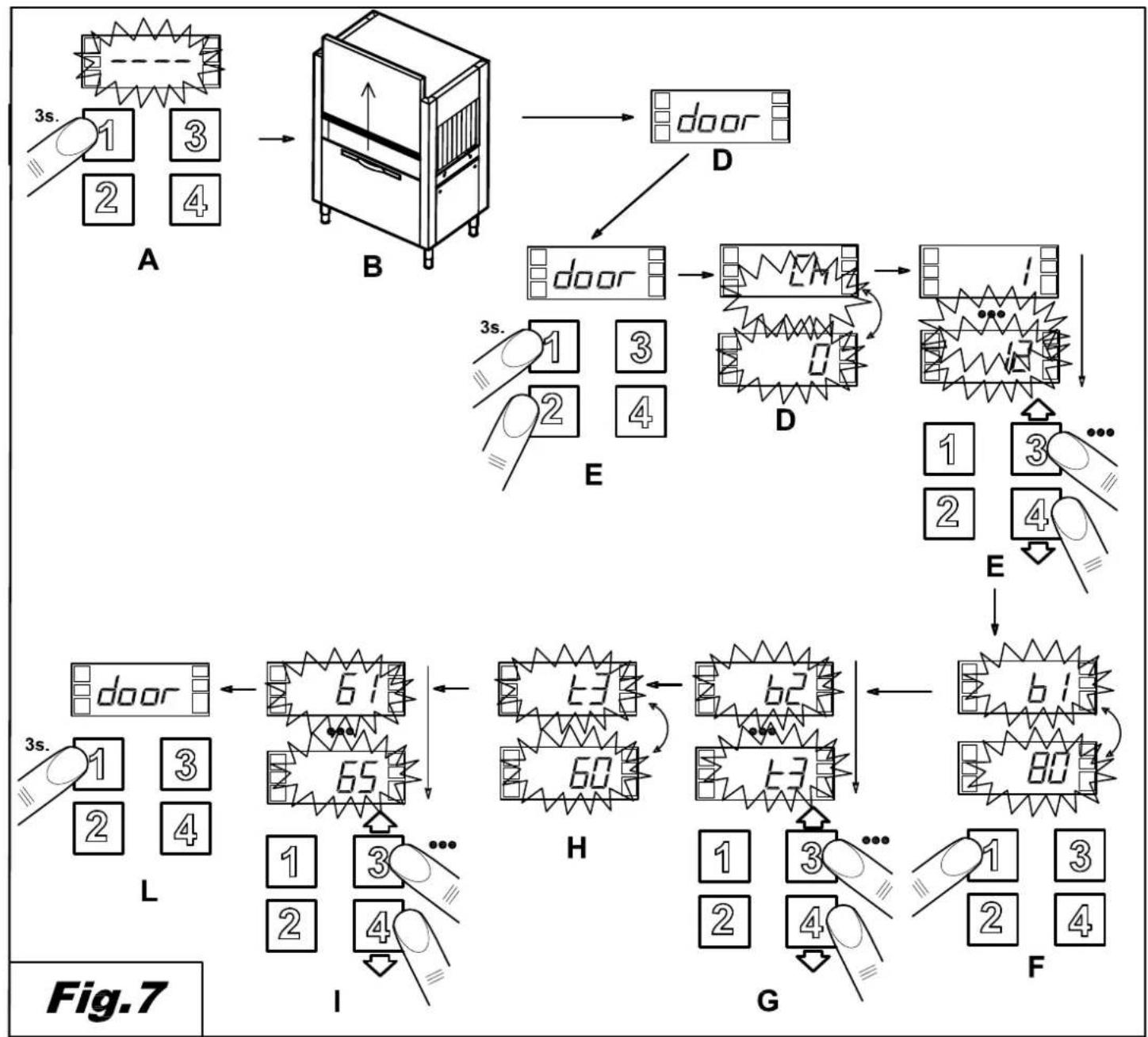
With reference to Figure 7
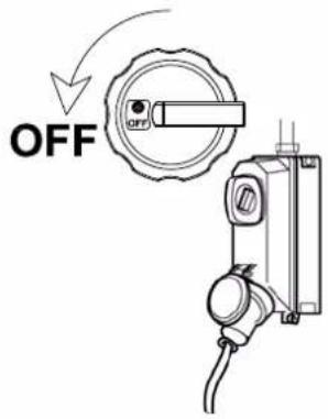
- Switch the machine off by pressing the line button (1) (Fig. 7/A)
- Open the door of the machine (Fig. 7/B)
- The display will show the message "door" (Fig. 7/C)
- Keep buttons (1) and (2) simultaneously pressed for a few seconds. (Fig. 7/D)
- The display will alternate messages "CH" and "0".
- Scroll through the numbers using buttons (3) and (4) until you reach "12". (Fig. 7/E)
- Press line button (1) (Fig. 7/F).
- Select the parameter you wish to regulate by scrolling through the list with buttons (1) and (2) (Fig. 7/G).
- The display will show, in sequence, the parameter and the set value (Fig. 7/H).
- Use buttons (3) and (4) to set the desired value. (Fig. 7/1)
- Once all regulations are concluded, keep the line button (1) pressed for a few seconds.
- The new settings are now memorised and the display will show the message “- - - ”. (Fig. 7/M)
7.9.1 temperatures
It is possible to set the washing and rinsing temperatures of all washing programmes, with the exception of the Glass programme.
| Parameter | Programme rinsing temperature | range of regulation (°C) |
| b1 | “SP1” | “oFF”,1,2...90 |
| b2 | “SP2” | |
| b3 | “AP1” |
| Parameter | Programme washing temperature | range of regulation (°C) |
| t1 | “SP1” | “oFF”,1,2...70 |
| t2 | “SP2” | |
| t2 | “AP1” |
7.9.2 dispensers
It is possible to adjust the dosing time, in seconds, for the rinse aid and detergent dispensers.
| Parameter | Dosing time | range of regulation (s) |
| dt | detergent | oFF,1,2...25 |
| bL | rinse aid | oFF,1,2...25 |
It is possible to manually load the dosing circuit.
Proceed as follows:
- Select, from the menu, parameter "bn" if you wish to load the rinse aid circuit, or "dn" if you want to load the detergent circuit.
- The display will show, in succession, "bn", "oFF", if you selected the rinse aid circuit, or "dn", "oFF" if you selected the detergent circuit.
- Keep button (3) pressed.
- The corresponding dispenser will start loading the circuit and the display will show "on" instead of "oFF"
- To stop the dispenser, simply release button (3).
7.10 User messages
| Display | Message description |
| door | open door |
| b | temperature of rinsing water |
| t | temperature of washing water |
| FI | first load activation |
| FILL | Tank filling |
| nodt | No detergent |
| nobL | No rinse aid |
| nobt | No water in the break tank |
| Fu A | firmware revision |
| C5 | software code |
| Hr | number of hours of work |
| End | The limit switch has tripped |
| temp | Awaiting correct tank temperature |
7.11 Function and status bars
The machine is equipped with coloured LED indicators that show the status and the functions of the machine in real time.
| ALARM BAR (LED) | ||
 | Green | No alarm |
| Orange | Alarm reporting a malfunction that does not require the machine to be stopped | |
| Red | Alarm that stops the machine from working | |
| FUNCTION BAR (LED) | ||
 | Fixed green | Machine in proper temperatures and ready to use |
| Moving green | Active washing | |
| Moving orange | Ongoing heating | |
7.12 Self-diagnosis
The machine is equipped with a self-diagnosis system that can detect and report different kinds of malfunctioning
| Display | Error description and possible solutions | |
| Er03 | Thermostat time out | The temperature of the boiler has not reached the set value in the pre-established time. Please contact the assistance centre |
| Er04 | Tank loading time out | Failure to reach the proper level of water in the washing tank.Switch the machine off and on again after making sure that the overflow device has been correctly installed, and after opening the water supply.If the problem continues, contact the assistance centre. |
| Er05 | Tank probe "open" | The probe that measures the temperature of the tank is not working.The heating function is impaired. Contact the assistance centre. |
| Er06 | Tank probe "closed" | |
| Er07 | Boiler probe "open" | The probe that measures the temperature of the probe is not working.The heating function is impaired. Contact the assistance centre. |
| Er08 | Boiler probe "closed" | |
| ErSF | Electromechanical safety | The mechanical safety on the basket conveyor has intervened. Switch the machine off and make sure there are no objects preventing the motion of the conveyor inside the machine; remove the obstruction, if identified. If the problem continues, please contact the assistance centre. |
| Er23 | Draining time out | The tank has not been drained after the double rinse.Switch the machine off and clean the relative filter.If the problem continues, please contact the assistance centre. |
| Er24 | Break-tank loading time out | Failure to reach the correct level of water in the break tankSwitch the machine off and then on again after opening the water supply and making sure that the capacity of the water mains is sufficient, in accordance with the data in the information plate.If the problem continues, contact the assistance centre. |
| Er51 | Temperatures electromechanical safety | The safety thermostats have intervened. Please contact the assistance centre. |
| Er99 | Expansion card failure | Problems with the expansion card which controls the dosing and pre-wash module.Switch the machine off and clean the relative filter. If the problem continues, please contact the assistance centre. |
Warning:
When the machine is switched off and then on, the alarm is initially reset, but will be displayed again if the cause of the problem is not solved.
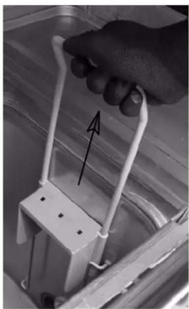
7.13 End of washing operations
With reference to Figure 8
- Stop the machine using the line button (Fig. 8/A)
- Switch off the wall-mounted main switch (Fig. 8/B)
- Open the doors, making sure they are firmly hooked to their supports. (Fig. 8/C)
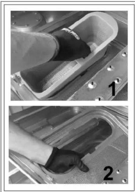
- Remove the horizontal filters, being particularly careful so as not to drop residues of food inside the washing tank. (Fig. 8/D)
- Lift the vertical filter and dispose of its contents. Use a hard brush to rinse the horizontal and the vertical filters. (Fig. 8/D)
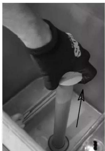
- Wearing latex or rubber gloves, pull out the overflow and allow the wash tank to empty. (Fig. 8/F)
- Accurately wash the bottom of the tank with a jet of water.
- Accurately wash the curtains.
- Remove any traces of dirt from the empty tank. At this point only, remove the safety filter of the pump and wash it under running water. (Fig. 8/G)
- The external parts of the machine must be cleaned when their surfaces are cool, using a sponge and non-foaming products that must be neither acid nor abrasive.
- Reinsert the overflow devices, the safety filters and the tray filters.
The machine is now ready to use.
WARNING: Do not wash the machine with water streams or high-pressure water directly applied to it, as any leaks into the electric components may compromise the regular function of the machine and of its safety systems, annulling the warranty.
It is advisable to leave the doors open, to avoid the formation of unpleasant smells.
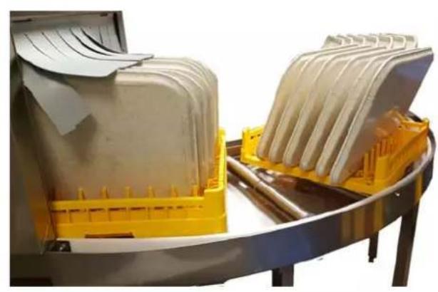
7.14 Positioning the dishes
With reference to figures 5,10 and 11
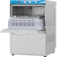
- This dishwasher is designed for washing plates, glasses, flatware, kitchen utensils, trays and small containers, always using specific 50x50 cm baskets which must be correctly loaded.
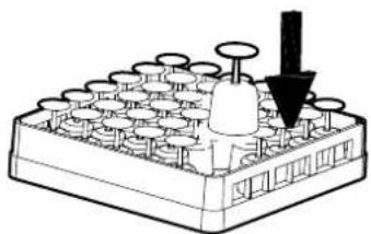
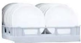
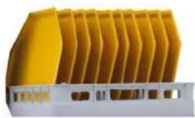
- Place cups and glasses upside down in the flat baskets. Stem glasses must only be washed in baskets with dividers which can be purchased separately fig. 5
- Place plates in the plate basket specifically designed with support shafts, with the inner surface facing upwards fig.5.
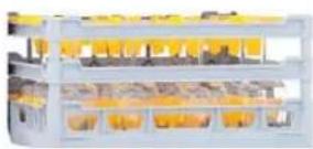
- Place flatware and teaspoons in the cutlery basket with the handles pointing downwards. Wash the various types together for optimum wash results fig.5.
- Trays and chopping boards of a maximum size of 530x325x60 mm (gastronorm 1/1) may be washed, using specific baskets without sides and inserts, loading them lengthwise in the direction of machine travel fig.5 and 10
Recommendations:
- Do not wash silver and stainless steel flatware in the same cutlery basket as this will tarnish the silver and may corrode the stainless steel.
- Always use the specific baskets designed for the various types of item to be washed (plates, glasses, cups, flatware, trays etc.) fig. 5.
- To save both detergent and electricity, only wash full, but not overloaded, baskets.
- Avoid overlapping items.
- To minimise maintenance, we recommend pre-cleaning items to be washed by removing left-over food particles such as fruit peel plus toothpicks, olive pits etc, which could otherwise partly clog the filter of the electro-pump, reducing wash performance and negatively affecting the quality of the final results fig.5.
- It is advisable to wash the dishes before food particles dry onto the surface. In the event of dried-on
food residue, dishes and flatware should be left to soak before being put in the machine
- Always select the wash programme and/or speed best suited to the type of items to be washed
- Always wash glasses with clean wash water and, if possible, at the start of the shift or after changing the water. Use the glasses cycle available on some models.
- To wash crystal glassware, only use baskets with special compartments and water with conductivity below 80 S
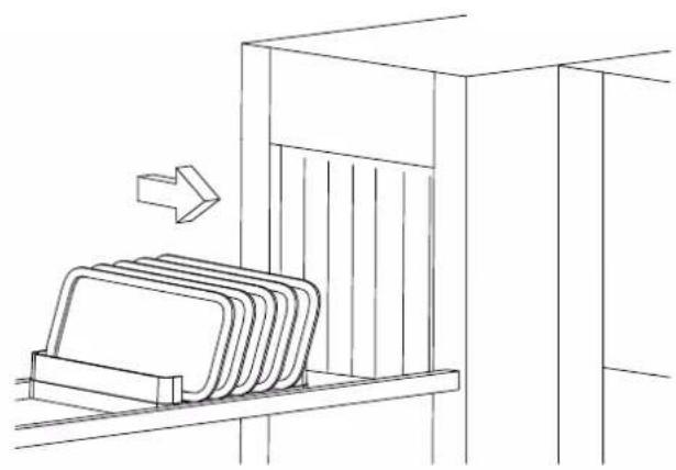
- If a corner configuration pre-wash is present, the trays must be loaded with any protruding parts facing the direction of travel Fig.11
- The machine is not designed for the continuous washing of predominantly large-sized items. The latter may nonetheless be washed, in between the washing of other dishes and using suitable baskets with tray supports.
- The machine is not designed for washing baskets.
- Incorrect loading or washing of large-sized items, for which the machine is not designed, may lead to abnormal leaks into the drain, resulting in the partial emptying of the tanks. In this case, the machine stops automatically and proceeds to refill with water until the correct level is restored. This may occur several times over the course of service.
- The baskets must be of a type suitable for the dishwasher's conveyor system and must be in good condition, especially on the bottom. Use the baskets in the machine's equipment as a reference.
- In the case of machines with corner configuration drying, trays must be placed in the dedicated basket, leaving one out as illustrated in figure 10
- Baskets sized 50x60 cm cannot be used.
Cap 8 MAINTENANCE
8.1 General rules
The machines are designed to minimise the need for maintenance. Carefully observe the rules below to ensure the long working life of the machine and trouble-free operation.
In any case, there are a few general rules to follow to keep the machine in perfect working order:
- keep the machine clean and tidy
- avoid allowing temporary or urgent repairs to become a matter of routine
Strict observance of routine maintenance rules is extremely important; all machine parts must be regularly checked to prevent problems and malfunctions from arising, thus reducing the time required for any maintenance interventions.
Warning!
- Before cleaning operations, disconnect the appliance from the power supply
- Before cleaning, wear gloves with a minimum cut protection of 3 in accordance with EN388.
- Cleaning the machine with products that contain chlorides in a concentration exceeding 50 ppm can lead to corrosion of the machine's stainless steel structure.
8.2 Periodical maintenance
With reference to Figure 9
Attention!
Before carrying out the following operations, wear gloves with a minimum cut protection of 3 in accordance with EN388.
- Disassemble the upper and lower rinsing arms.
- Clean all nozzles, removing any obstruction found, and reassemble them.
- Disassemble the curtains and clean them with a nylon brush under running water.
- Disassemble the upper and lower washing arms and rinse them.
- Remove the washing pump filter and rinse it.
- Clean the washing tank thoroughly.
- Due to the calcium and magnesium salts present in the water, after a certain period of operation, which varies according to the hardness of the water used, a calcareous layer deposits in the inner surfaces of the boiler tank and of the pipes, compromising the proper functioning of the machine.
- It is therefore necessary to periodically remove incrustations, an operation that should be carried out by technically qualified personnel.
- If the machine is to be left unused for a long period of time, the steel surfaces must be greased with Vaseline oil.
- If there is danger of water freezing, have technically qualified personnel drain the boiler water and the washing pump water.
- If intense calcareous deposits form inside the machine in the presence of water, use an incrustation removing product.
- To remove the incrustations, carefully follow the instructions of the manufacturer of the product, or seek the assistance of qualified personnel. In any case, always rinse the machine thoroughly after removing incrustations.
- Make sure the safety devices are working efficiently.
- If the steam condensing battery is dirty, disassemble it and clean the spaces between the flaps using compressed air.
- REMINDERS:
Every mechanical and electromechanical part of the machine is subject to physical wear. A qualified technician must carry out periodical inspections on:
- Conveying system sledges
- Washing/rinsing electro-pump seals
- Door guides and springs
- Remote control switch
- Safety devices
In addition, it is obligatory to test and inspect the devices that are not part of the machine, such as earthing differential, proper earthing, automatic switches and/or fuses in the power line, every electric conductor, the status of water pipes, discharge system, proper functioning of dispensers.
- In case of malfunctioning, seek only technical assistance centres authorised by the manufacturer or by the manufacturer's dealer.
text_image
UKDISHWASHER INSTRUCTIONS MANUAL
Cap 9 DISPOSAL
Our machines do not contain any material that requires particular disposal procedures. (Applicable in European Union countries and in countries with selective waste collection) The marking on the product or on its documents means that the product must not be disposed of as domestic waste at the end of its working life. To avoid damages to the environment or to the health due to the incorrect disposal of waste, users should separate
this product from other kinds of waste, and recycle it responsibly to promote the sustainable reuse of material resources.
Domestic users should contact their dealer, or the local office in charge of providing information regarding selective waste collection and recycling options for this kind of product.
Corporate users should contact their supplier and verify the terms and conditions of the purchase contract.
This product must not be disposed of with other commercial waste.
Cap 10 ENVIRONMENT
ENVIRONMENTALLY SAFE USE
- A conscious use of the dish washer may help reduce environmental impact, simply by following a few indications in every day use, such as:
- Only wash fully loaded baskets.
- Switch the dish washer off when not in use.
- Keep the machine closed when in stand-by mode.
- Use programmes suitable for the level of dirt.
• Supply the machine with hot water, if the water is heated with gas.
- Make sure that the drained water is conveyed to suitable sewage system.
- Do not exceed the recommended detergent doses.
The manufacturer is entitled to carry out electrical, technical and aesthetic modifications to the machine, and/or to replace parts without previous notice, whenever deemed necessary, in order to offer a reliable, long-lasting product with advanced technology.
The manufacturer is entitled, according to the property law described in this document, to forbid this document from being reproduced and made public through any means without the manufacturer's express written authorisation. The manufacturer is entitled to modify this document whenever necessary, in order to improve it.
INHALTSVERZEICHNIS
CAP 1 RISIKEN UND WICHTIGE WARNHINWEISE ....3
CAP 2 VORWORT....7
CAP 3 HANDLING UND TRANSPORT DER MASCHINE....7
3.1 TRANSPORT UND VERPACKUNG 7
3.2 HANDLING....7
3.3 EINLAGERUNG....8
3.4 ABMESSUNGEN 8
CAP 4 INSTALLATION....8
natural_image
Line drawing of a semi-truck with front and side panels (no text or symbols)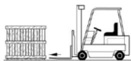
text_image
Two triangular warning signs: one with a cross symbol and the other with a hand gesture.flowchart
graph TD
    A["Incineration Chamber"] --> B["Warning Signals"]
    B --> C["Recovery to Safety"]
    C --> D["Warning Signals"]
    D --> E["Recovery to Safety"]
    E --> F["Warning Signals"]
    F --> G["Recovery to Safety"]
    G --> H["Warning Signals"]
    H --> I["Recovery to Safety"]
    I --> J["Warning Signals"]
    J --> K["Recovery to Safety"]
    K --> L["Warning Signals"]
    L --> M["Recovery to Safety"]
    M --> N["Warning Signals"]
    N --> O["Recovery to Safety"]
    O --> P["Warning Signals"]
    P --> Q["Recovery to Safety"]
    Q --> R["Warning Signals"]
    R --> S["Recovery to Safety"]
    S --> T["Warning Signals"]
    T --> U["Recovery to Safety"]
    U --> V["Warning Signals"]
    V --> W["Recovery to Safety"]
text_image
< 70 dB (A) < 70 dB (A) < 70 dB (A) < 70 dB (A)natural_image
Illustration of a hand using a tool to lift a component, with no visible text or symbolsnatural_image
Architectural diagram showing structural components and room layouts (no text or labels)natural_image
Technical line drawing of a pipe installation with a valve and brick wall (no text or symbols)natural_image
Pure technical line drawing of a mechanical component or structure without any text, numbers, or symbolsnatural_image
Pure technical line drawing of a mechanical or architectural component without any text, numbers, or symbols
text_image
B Hnatural_image
Close-up of a pipe fitting with coiled tubing, mounted on a wall (no visible text or symbols)natural_image
Close-up of a metallic mechanical component with two white cylindrical pins and a rectangular housing (no visible text or symbols)natural_image
Close-up of a blue industrial sensor device with threaded connector and attached cable (no visible text or symbols)natural_image
Technical line drawing of a mechanical spring assembly with dimension L (no text or symbols)text_image
Diagram showing a device with a warning symbol and circular component, including an arrow and exclamation mark.text_image
Symbol of a waste bin with crossed-out lines and a blank rectangular base, indicating no waste or disposal.Cap 9 ENTSORGUNG
natural_image
Line drawing of a semi-truck with front wheel and side grille (no text or symbols)text_image
Two triangular warning signs: one with a cross symbol and the other with a hand gesture.Risque de coupure
text_image
< 70 dB (A) < 70 dB (A) < 70 dB (A) < 70 dB (A)natural_image
Illustration of a hand using a tool to lift a component, with no visible text or symbolsnatural_image
3D architectural rendering of a building complex with multiple tiers and structural elements (no visible text or symbols)natural_image
Technical line drawing of a pipe installation with a brick wall and valve (no text or symbols)natural_image
Pure technical line drawing of a mechanical component or tank assembly (no text or symbols)
natural_image
Pure technical line drawing of a structural frame with no text, numbers, or symbolsnatural_image
Close-up of a pipe with a coiled hose and valve, mounted on a wall (no visible text or symbols)natural_image
Close-up of a mechanical assembly with white components and a blue connector (no visible text or symbols)natural_image
Close-up of a blue industrial sensor device with attached cable and metal connector (no visible text or symbols)natural_image
Technical line drawing of a mechanical spring assembly with dimension L (no text or symbols)text_image
Technical diagram showing a mechanical component with an annotated circular component and warning symbolnatural_image
Line drawing of a semi-truck with front grille and side-mounted mast (no text or symbols)text_image
Two triangular warning signs: one with a cross symbol and the other with a hand gesture.Pericolo di taglio
text_image
< 70 dB (A) < 70 dB (A) < 70 dB (A) < 70 dB (A)natural_image
Illustration of a hand using a tool to lift a component, with no visible text or symbolsnatural_image
Isometric view of a building interior with structural elements and structural supports (no text or symbols visible)natural_image
Technical line drawing of a pipe installation with a brick wall and pipe fittings (no text or symbols)natural_image
Pure technical line drawing of a mechanical or architectural component without any text, numbers, or symbolsnatural_image
Pure technical line drawing of a mechanical or architectural component without any text, numbers, or symbols
text_image
B Inatural_image
Close-up of a pipe with coiled tubing and a flanged connector, mounted indoors (no visible text or symbols)natural_image
Close-up of a metallic mechanical component with two cylindrical components and a central shaft (no visible text or symbols)
natural_image
Close-up of a blue industrial sensor device with threaded connector and attached cable (no visible text or symbols)natural_image
Technical line drawing of a mechanical spring assembly with dimension L (no text or symbols)text_image
Technical diagram showing a mechanical component with a circular component and warning symbol indicating clockwise rotation.text_image
Technical schematic diagram of a water treatment or filtration system with numbered components and flow pathstext_image
Technical schematic diagram of a water treatment or filtration system with numbered components and equipment layoutnatural_image
Symbol of a waste bin with no text or numbers, crossed by diagonal lines and a solid black rectangle below (no text or symbols present)Cap 9 SMALTIMENTO
natural_image
Line drawing of a semi-truck with front grille and side-mounted mast (no text or symbols)text_image
< 70 dB (A) < 70 dB (A) < 70 dB (A) < 70 dB (A)natural_image
Illustration of a hand using a tool to lift a component, with no visible text or symbolsnatural_image
3D architectural rendering of a building complex with multiple windows and structural elements (no text or symbols visible)natural_image
Technical line drawing of a pipe installation with a brick wall and valve (no text or symbols)natural_image
Pure technical line drawing of a mechanical or architectural component without any text, numbers, or symbolsnatural_image
Technical line drawing of a mechanical or architectural component with pipes and supports (no text or symbols)
text_image
B Inatural_image
Close-up of a pipe with coiled tubing and a small component, no visible text or symbolsnatural_image
Close-up of a metallic mechanical component with cylindrical and circular features (no visible text or symbols)natural_image
Close-up of a blue industrial sensor device with threaded connector and attached cable (no visible text or symbols)natural_image
Technical line drawing of a mechanical screw or drill bit with dimension L (no text or symbols)text_image
Technical diagram showing a mechanical component with an arrow indicating rotational motion and a warning symbol.text_image
Technical schematic diagram of a water treatment or filtration system with numbered components and equipment layouttext_image
Technical schematic diagram of a fluid or filtration system with numbered components and labeled partstext_image
Symbol of a waste bin with crossed-out lines and a blank rectangular base, indicating no waste or disposal.Cap 9 ELIMINACIÓN
natural_image
Line drawing of a semi-truck with front grille and side-mounted mast (no text or symbols)text_image
Two triangular warning signs: one with a cross symbol and the other with a hand gesture.Perigo de corte
text_image
< 70 dB (A) < 70 dB (A) < 70 dB (A) < 70 dB (A)natural_image
Illustration of a hand holding a tool with a magnified inset showing a device (no text or symbols)natural_image
Architectural 3D rendering of a multi-story building with structural elements and windows (no text or symbols visible)natural_image
Technical line drawing of a pipe installation with a brick wall and pipe fittings (no text or symbols)natural_image
Pure technical line drawing of a U-shaped pipe or drain system without any text, labels, or symbolsnatural_image
Pure technical line drawing of a mechanical or architectural component without any text, numbers, or symbols
text_image
B Inatural_image
Close-up of a pipe with coiled tubing and a flanged connector, mounted on a wall (no text or symbols visible)natural_image
Close-up of a mechanical component with two white cylindrical pins and a metallic handle (no visible text or symbols)natural_image
Close-up of a blue industrial sensor device with threaded connector and attached cable (no visible text or symbols)natural_image
Technical line drawing of a mechanical spring assembly with dimension L (no text or symbols)text_image
Diagram showing a device with a warning symbol and circular component, indicating clockwise rotation or clockwise motion.text_image
Symbol of a waste bin with crossed-out lines and a blank rectangular base, indicating no waste or disposal.Cap 9 ELIMINAÇÃO
natural_image
Line drawing of a semi-truck with front wheel and side grille (no text or symbols)text_image
< 70 dB (A) < 70 dB (A) < 70 dB (A) < 70 dB (A)natural_image
Illustration of a hand holding a tool with an arrow indicating motion (no text or symbols)Placér maskinen i overensstemmelse med anvisningerne i den generelle måltegning for installationen, som følger med separat. Kontrollér, at positionen er korrekt i forhold til kravene til vedligeholdelse.
natural_image
Isometric view of a multi-story building with windows and structural elements (no text or symbols visible)natural_image
Technical line drawing of a pipe connection with a brick wall and outlet (no text or symbols)5.2 Hydraulisk tilslutning
natural_image
Pure technical line drawing of a mechanical or architectural component without any text, numbers, or symbolsnatural_image
Technical line drawing of a structural component with pipes and supports (no text or symbols)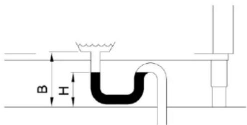
text_image
B Inatural_image
Close-up of a flexible pipe fitting with a coiled hose, mounted on a wall (no visible text or symbols)natural_image
Close-up of a mechanical or electrical component with metallic pins and a central shaft (no visible text or symbols)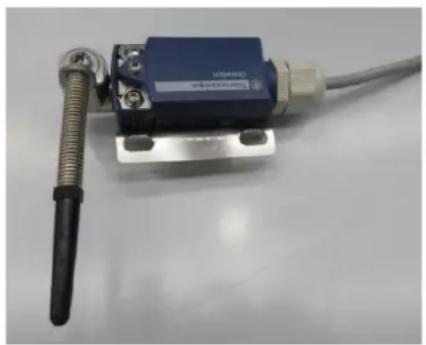
natural_image
Close-up of a blue industrial sensor device with threaded connector and attached cable (no visible text or symbols)natural_image
Technical line drawing of a mechanical spring assembly with dimension L (no text or symbols)text_image
Diagram showing a mechanical component with an arrow and warning symbol, including a warning triangle.text_image
Technical schematic diagram of a fluid or filtration system with numbered components and flow pathstext_image
Technical schematic diagram of a water treatment or filtration system with numbered components and equipment layoutnatural_image
Symbol of a waste bin with no text or numbers, crossed by diagonal lines and a solid rectangle below (no text or symbols present)Cap 9 BORTSKAFFELSE
INNEHÅLLSFÖRTECKNING
KAP 1. RISKER OCH VIKTIGA VARNINGAR ....3
KAP 2. FÖRORD....6
KAP 3. HANTERING OCH TRANSPORT AV MASKINEN....7
3.1 TRANSPORT OCH EMBALLAGE 7
3.2 HANTERING....7
3.3 MAGASINERING....7
3.4 DIMENSIONER 7
KAP 4. INSTALLATION ....7
4.1 FAROZONER 7
4.2 VIKTIG VARNING 9
4.3 BULLERTRYCKNIVÅ 9
4.4 UPPACKNING OCH UPPSTÄLLNING 9
4.5 OMGIVNINGSFÖRHÅLLANDEN 10
KAP 5. INSTALLATION....10
5.1 ELEKTRISK ANSLUTNING 10
5.2 VATTENANSLUTNING....11
5.3 ANSLUTNING TILL AVLOPP 12
natural_image
Line drawing of a semi-truck with front grille and side-mounted camera (no text or symbols)text_image
Three triangular warning symbols: running person, crosshair with arrows, and directional signtext_image
< 70 dB (A) < 70 dB (A) < 70 dB (A) < 70 dB (A)natural_image
Illustration of a hand holding a tool with an arrow indicating motion (no text or symbols)natural_image
3D architectural rendering of a multi-story building with structural elements and windows (no text or symbols visible)natural_image
Technical line drawing of a pipe installation with a brick wall and valve (no text or symbols)5.2 Vattenanslutning
natural_image
Pure technical line drawing of a mechanical component or tank assembly without any text, numbers, or symbolsnatural_image
Pure technical line drawing of a structural component without any text, numbers, or symbols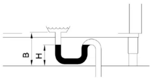
text_image
B Inatural_image
Close-up of a pipe with flexible hose and connector, no visible text or symbolsnatural_image
Close-up of a metallic mechanical component with two white cylindrical components and a blue handle (no visible text or symbols)natural_image
Close-up of a blue industrial sensor device with attached cable and metal connector (no visible text or symbols)natural_image
Technical line drawing of a mechanical spring assembly with dimension L (no text or symbols)text_image
Technical diagram showing a mechanical component with an annotated circular motion indicator and warning symboltext_image
Technical schematic diagram of a water treatment or filtration system with numbered components and flow pathstext_image
Technical schematic diagram of a water treatment or filtration system with numbered components and equipment layout| 1 | KNAPP FÖR ON/OFF | 5 | INFORMATIONSDISPLAY |
| 2 | KNAPP FÖR START/STOPP | 6 | FUNKTIONSFÄLT (LYSDIODER) |
| 3 | PROGRAMVALSKNAPP | 7 | LARMFÄLT (LYSDIODER) |
| 4 | PROGRAMVALSKNAPP |
natural_image
Line drawing of a semi-truck with front grille and side-mounted mast (no text or symbols)text_image
Three triangular warning symbols: falling person, snowflake with cross, and hand pointing signflowchart
graph TD
    A["Incident"] --> B["Process Room"]
    B --> C{Safety Hazard}
    C -->|Yes| D["Warning Device"]
    C -->|No| E["Warning Device"]
    D --> F["Control Unit"]
    E --> F
    F --> G["Refrigeration Tank"]
    G --> H["Storage Tank"]
    H --> I["Recirculation Pipe"]
    I --> J["Exhaust Structure"]
    style A fill:#f9f,stroke:#333
    style J fill:#bbf,stroke:#333
text_image
< 70 dB (A) < 70 dB (A) < 70 dB (A) < 70 dB (A)natural_image
Illustration of a hand holding a tool with a directional arrow indicating movement (no text or symbols)text_image
H Mod. S/N V N HZ IP DVGW W A Bar (.....kPa) T °C Max...natural_image
3D architectural rendering of a building complex with multiple tiers and structural elements (no visible text or symbols)natural_image
Technical line drawing of a pipe installation with a brick wall and valve (no text or symbols)natural_image
Pure technical line drawing of a mechanical or architectural component without any text, numbers, or symbols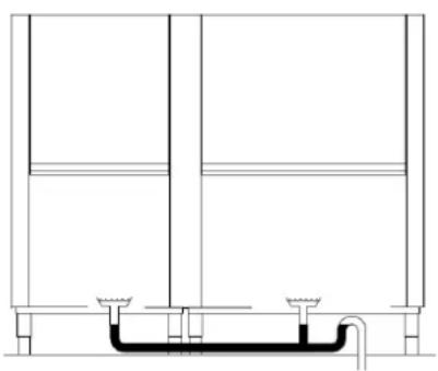
natural_image
Technical line drawing of a structural component with no visible text or symbolsnatural_image
Close-up of a pipe fitting with a flexible hose, mounted on a wall (no visible text or symbols)natural_image
Close-up of a mechanical component with two white cylindrical pins and a metallic bracket (no visible text or symbols)natural_image
Close-up of a blue industrial sensor device with attached cable and metal connector (no visible text or symbols)natural_image
Technical line drawing of a mechanical spring assembly with dimension L (no text or symbols)text_image
Diagram showing a mechanical component with an arrow and warning symbol, including a warning triangle.text_image
Technical schematic diagram of a water treatment or filtration system with numbered components and flow pathstext_image
Technical schematic diagram of a water treatment or filtration system with numbered components and equipment layoutnatural_image
Symbol of a waste bin with no text or labels, crossed by diagonal lines and a solid black rectangle below (no readable text or symbols)КЕФ. 9 АПОРРИΨΗ
natural_image
Line drawing of a semi-truck in profile view (no text or symbols)text_image
< 70 dB (A) < 70 dB (A) < 70 dB (A) < 70 dB (A)natural_image
Illustration of a hand holding a tool with a ruler inserted, next to a device (no text or symbols visible)natural_image
3D architectural rendering of a multi-story building with structural elements and windows (no text or symbols visible)natural_image
Technical line drawing of a pipe installation with a brick wall and pipe fittings (no text or symbols)natural_image
Pure technical line drawing of a mechanical or electrical component without any text, numbers, or symbolsnatural_image
Pure technical line drawing of a mechanical or architectural component with no text, numbers, or symbols