
GLDA696PSS - Washing machine GE - Free user manual and instructions
Find the device manual for free GLDA696PSS GE in PDF.

| Product Type | Built-in Dishwasher |
| Brand | GE |
| Model | GLDA696PSS |
| Minimum Cutout Dimensions (W x D x H) | 61 cm x 61 cm x 87 cm ± 6 mm |
| Electrical Supply | 120 V, 60 Hz, 15 or 20 A, individual circuit |
| Tub Material | Stainless Steel |
| Recommended Water Temperature | 49 to 65 °C (120 to 150 °F) |
| Required Water Pressure | 1.4 to 8.3 bar (20 to 120 psi) |
| Maximum Drain Hose Length | 3 m (10 ft) |
| Drain Type | Anti-siphon device or high drain loop (min 81 cm) |
| Capacity | Not specified in the manual |
| Wash Cycles | Rinse only, other cycles per user manual |
| Sound Level | Not specified in the manual |
| Options | Noise reduction kit (some models), bulk dispenser (depending on model) |
| Water Hardness Setting | Yes, via test strip (models with bulk dispenser) |
| Warranty | Standard GE warranty (not specified in this manual) |
| Maintenance | Clean the door and gasket regularly; check filters |
| Installation | Requires plumbing and electrical skills; duration 1 to 3 hours |
Frequently Asked Questions - GLDA696PSS GE
User questions about GLDA696PSS GE
0 question about this device. Answer the ones you know or ask your own.
Ask a new question about this device
Download the instructions for your Washing machine in PDF format for free! Find your manual GLDA696PSS - GE and take your electronic device back in hand. On this page are published all the documents necessary for the use of your device. GLDA696PSS by GE.
USER MANUAL GLDA696PSS GE
Installation Instructions
Built-In Dishwasher
If you have questions, call 800.GE.CARES (800.432.2737) or visit our Website at: GEAppliances.com In Canada call 1.800.561.3344 or www.GEAppliances.ca

BEFORE YOU BEGIN
Read these instructions completely and carefully.
IMPORTANT – Observe all governing codes and ordinances.
- Note to Installer – Be sure to leave these instructions for the consumer's and local inspector's use.
- Note to Consumer – Keep these instructions with your Owner's Manual for future reference.
- Skill Level – Installation of this dishwasher requires basic mechanical, electrical and plumbing skills. Proper installation is the responsibility of the installer. Product failure due to improper installation is not covered under the GE Appliance Warranty. See warranty information.
- Completion Time – 1 to 3 Hours. New installations require more time than replacement installations.
IMPORTANT – The dishwasher MUST
be installed to allow for future removal from the enclosure if service is required.
If you received a damaged dishwasher, you should immediately contact your dealer or builder.
Optional Accessories – See the Owner's Manual for available custom panel kits.
FOR YOUR SAFETY
Read and observe all CAUTIONS and WARNINGS shown throughout these instructions. While performing installations described in this booklet, gloves and either safety glasses or goggles should be worn.

natural_image
Line drawing of an open kitchen appliance with visible dish and control panel (no text or symbols)READ CAREFULLY. KEEP THESE INSTRUCTIONS.
Stainless Steel Tub Models

imagination at work
Installation Preparation
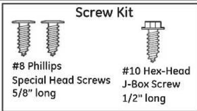
PARTS SUPPLIED WITH INSTALLATION KIT:
Two #8-18 x 5/8" Phillips special head screws, to secure dishwasher to underside of countertop or sides of cabinets.
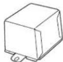
Junction box cover and #10-1/2" hex-head screw
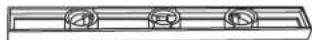
Side and top trim
Trim Panel Accessory Kit (not shown) (Custom panel models only)
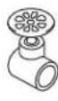
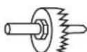
Sound upgrade kit (some models)
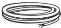
Drain hose (78"), drain hose hanger and hose clamp
Literature, product samples and/or coupons
Hard water test strip (Models with Bulk Dispenser)
MATERIALS YOU WILL NEED:
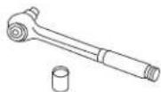
Ferrule, compression nut and 90° Elbow (3/8" NPT external thread on one end, opposite end sized to fit water supply)
Thread seal tape
UL-listed wire nuts (3)
Materials For New Installations Only:
Air gap for drain hose, if required
Waste tee for house plumbing, if applicable
Electrical cable or power cord, if applicable
Screw-type hose clamps
Strain relief for electrical connection
Hand shut-off valve
Water line 3/8" min. copper
Coupler for extending drain line, if applicable
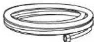
□ GPF10L 10' drain hose, if needed
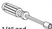
TOOLS YOU WILL NEED:
Phillips-head screwdriver
1/4" and 5/16" nutdriver
6" Adjustable wrench
Level
Carpenter's square
Measuring tape
Safety glasses
Flashlight
Bucket to catch water when flushing the line
15/16" socket
Gloves
For New Installations Only:
L Tubing cutter
Drill and appropriate bits
Hole saw set
text_image
Screw Kit #8 Phillips Special Head Screws 5/8" long #10 Hex-Head J-Box Screw 1/2" long
text_image
Side Trim Side Trim Top Trim
natural_image
Technical line drawing of a mechanical component labeled 'Sound Up (Some Mo)' (no other text or symbols)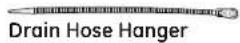

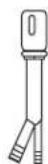
Hard Water Test Strip (Models with
Bulk Dispenser)
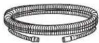
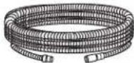
Drain Hose (78")
Junction Box Cove

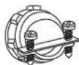
Hose Clamp
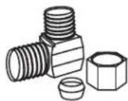
90° Elbow,
Ferrule and
Compression Nut
Hand
Shut-Off
Valve

Thread
Seal Tape

Wire Nuts (3)

Waste Tee
Electrical Cable
(or Power Cord, if applicable)
Hot Water Line
GPF10L
10' Drain Hose
Air
Gap


Screw-Type
Hose Clamps
Strain Relief

Coupler

Head
Screwdriver
1/4" and
5/16" Nutdriver
Level
1/4" and
15/16" Socket
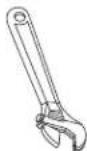
6" Adjustable
Wrench

Tubing Cutter

Carpenter's Square

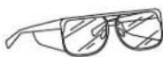

Safety GlassesFlashlight Measuring Tape

Gloves

Bucket Hole Saw Set Drill and Bits
PREPARE DISHWASHER ENCLOSURE

To reduce the risk of shock, fire, or injury to persons, the installer must ensure that the dishwasher is completely enclosed at the time of installation.
- The rough cabinet opening must have a minimum width and depth of 24" and height of 34-1/2" ± 1/4" from the floor to the underside of the countertop.
- The back wall should be free of pipes or wires.
- Adjacent cabinets should be square and plumb to ensure a good fit. Refer to Figure A
- For a corner installation, allow 2" minimum clearance between the dishwasher and the adjacent wall.
- Provide at least 28-3/8" in front of the dishwasher to allow the dishwasher door to open fully. Refer to Figure B

text_image
This Wall Area Must Be Free of Pipes or Wires 34-1/2" ± 1/4" Underside of Countertop to Floor 5" 4" 5" 4" Min. 24" Cabinets Square and Plumb 6" 24" Min. Floor MUST be Even with Room Floor Plumbing and Electric Service Must Enter Shaded AreaFigure A
- Make sure the floor is level inside the opening and even with the finished floor of the kitchen. This will facilitate removal of the dishwasher at a later date for service, if needed.
Special consideration for a dishwasher installed on a elevated platform
The elevated platform must be flat and level.
- The dishwasher must be installed no more than 10 feet from sink for proper drainage.
- The dishwasher must be fully enclosed on the top, sides and back.
- The dishwasher must not support any part of the enclosure.
text_image
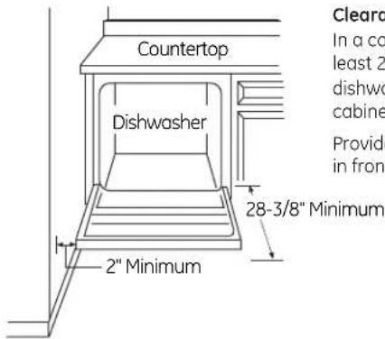
Countertop Dishwasher 2" Minimum Clear In a co least 2" dishwo cabine Provide in front 28-3/8" MinimumFigure B
Clearances:
In a corner installation, provide at least 2" clearance between the dishwasher and the adjacent cabinet, wall, or other appliance. Provide at least 28-3/8" of clearance in front of the dishwasher.
PREPARE DRAIN PLUMBING
Drain Requirements
- Drain hose must not exceed 10 feet in length.
- A high drain loop or air gap is required. See below.
Drain Method
The type of drain installation depends on the following:
- Do local codes or ordinances require an air gap?
- Is waste tee less than 18" above the floor?
If the answer to either question is yes, an air gap must be used. Refer to Method 1 (Figure C) in the adjacent illustrations.
If both answers are no, either an air gap or high drain loop may be used. Refer to Method 1 (Figure C) or Method 2 (Figure D) in the adjacent illustrations
NOTE: Drain hose elevation must not exceed 48".
Special consideration for a dishwasher installed on a elevated platform
If the dishwasher is installed on an elevated platform, a high drain loop of at least 32" above the platform must be provided in addition to the air gap or drain loop requirement determined above. This is necessary for proper drain performance.

CAUTION
An air gap MUST BE USED if the drain hose is connected to waste tee or disposer lower than 18" above the floor level. Failure to provide the proper drain connection height with an air gap or 32" minimum, high drain loop will result in improper draining of the dishwasher, which may cause damage.

PRECAUCIÓN
METHOD 1-Air Gap with Waste Tee or Disposer
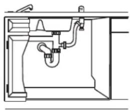
natural_image
Technical line drawing of a mechanical or plumbing assembly with pipes and fixtures (no text or symbols)Waste Tee Installation
Figure C
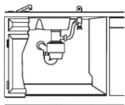
natural_image
Technical line drawing of a mechanical or plumbing assembly with no visible text or symbolsDisposer Installation
METHOD 2-High Drain Loop with Waste Tee or Disposer
Use the drain hose hanger included in the installation kit to attach the drain hose to the underside of the countertop. Attachment will be made in a later step.
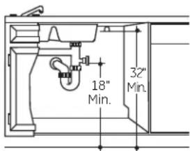
text_image
18" Min. 32" Min.Waste Tee Installation
Figure D
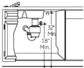
text_image
32" Min. 18" Min.Disposer Installation
Install waste tee or disposer and the air gap according to the manufacturer's instructions.
Cabinet Preparation for drain line
Drill a 1-1/2" diameter hole in the cabinet wall within the shaded area shown in Figure A for the drain hose. Make sure there are no sharp edges. The drain hose will be passed through this hole and connected to the drain in a later step.
IMPORTANT - When
connecting the drain line to a disposer, check to be sure that drain plug has been removed. Dishwasher will not drain if plug is left in place.

Remove
Drain
Plug
PREPARE ELECTRICAL WIRING
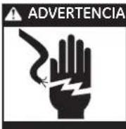
WARNING

FOR PERSONAL SAFETY: Remove house fuse or open circuit breaker before beginning installation. Do not use an extension cord or adapter plug with this appliance.
ADVERTENCIA

Electrical Requirements
- This appliance must be supplied with 120V, 60Hz., and connected to an individual properly grounded branch circuit protected by a 15- or 20-ampere circuit breaker or time-delay fuse.
- Wiring must be 2 wire with ground and rated for 75^ (176°F).
- If the electrical supply does not meet the above requirements, call a licensed electrician before proceeding.
Grounding Instructions-Permanent Connection
This appliance must be connected to a grounded-metal, permanent wiring system, or an equipment-grounding conductor must be run with the circuit conductors and be connected to the equipment-grounding terminal or lead on the appliance.
Grounding Instructions-Power Cord Models
This appliance must be grounded. In the event of a malfunction or breakdown, grounding will reduce the risk of electric shock by providing a path of least resistance for electric current. This appliance is equipped with a cord having an equipment-grounding conductor and a grounding plug. The plug must be plugged into an appropriate outlet that is installed and grounded in accordance with all local codes and ordinances.
WARNING

The improper connection of the equipment grounding conductor can result in a risk of electric shock. Check with a qualified electrician or service representative if you are in doubt that the appliance is properly grounded.
ADVERTENCIA

text_image
Alternate Receptacle Location 1-1/2" Dia. Hole (Max.) 3" from Cabinet 18" 6" 6" Receptacle Location Area 24" from Wall Ground Black White Figure EFor models equipped with power cord: Do not modify the plug provided with the appliance; if it will not fit the outlet, have a proper outlet installed by a qualified technician.
Cabinet Preparation and Wire Routing
- The wiring may enter the opening from either side, rear or the floor within the shaded area dimensioned in Figure A and illustrated above.
- Cut a 1-1/2" max. diameter hole to admit the electrical cable. Cable direct connections may pass through the same hole as the drain hose and hot water line, if convenient. If cabinet wall is metal, the hole edge must be covered with a bushing.
Note: Power cords with plug must pass through a separate hole.
Electrical Connection to Dishwasher
Electrical connection is on the right front of dishwasher.
- For cable direct connections the cable must be routed as shown in Figure E. Cable must extend a minimum of 24" from the rear wall.
- For power cord connections, install a 3-prong grounding type receptacle in the adjacent cabinet rear wall, 6" min. or 18" max. from the opening, 6" to 18" above the floor. The receptacle must be accessible and therefore cannot be installed in the back wall of the dishwasher enclosure.
Installation Preparation-Hot Water Supply
PREPARE HOT WATER SUPPLY
Hot Water Line
- The line may enter from either side, rear or floor within the shaded area shown in Figure F.
- The line may pass through the same hole as the electrical cable and drain hose, or an additional 1-1/2" diameter hole may be cut to accommodate the water line. If a power cord with plug is used, the water line must not pass through the power cord hole.
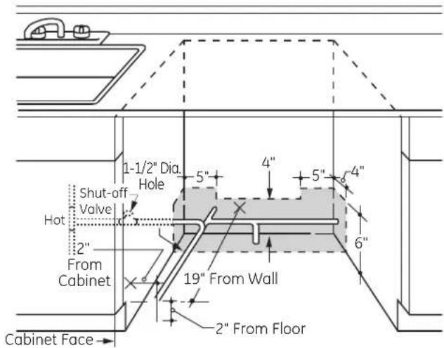
text_image
1-1/2" Dia. Hole 5" 4" 5" 4" Shut-off Valve Hot 2" From Cabinet 19" From Wall 2" From Floor 6" Cabinet FaceFigure F
Water Line Connection
- Turn off the water supply.
- Install a hand shut-off valve in an accessible location, such as under the sink. (Optional, but strongly recommended and may be required by local codes.)
- The water connection is on the bottom-left side of the dishwasher. Install the hot water inlet line, using 3/8" or larger copper tubing. Route the line as shown in Figure F and extend forward at least 19" from rear wall.
- Adjust the water heater to deliver water between 120°F and 150°F.
- Flush water line to clean out debris. Use a bucket to catch water and debris.
- The hot water supply line pressure must be between 20 and 120 PSI.

The hot water supply line pressure must be at least 20 PSI. Lower pressures could cause the water valve to leak and cause water damage.

Do not remove the wood base until you are ready to install the dishwasher. The dishwasher will tip over when the door is opened if the base is removed.

PRECAUCIÓN
- Locate the items in the installation package and set aside for use in the listed steps.
- Trim pieces - Step 2
- Junction box cover - Step 7 or Step 18
- Drain hose and clamp - Step 10
- Screw Kit - Step 15
- Drain hose hanger - Step 17
- Owner's Manual – Step 19 and Step 24
- Hard Water test strip – Step 21
• Sound upgrade kit (selected models) – Step 22 - Product samples and/or coupons – Step 24
STEP 2 - INSTALL TRIM PIECES
In this step, you will need the trim pieces set aside in Step 1.
- Press top trim piece onto top of tub fl ange. Start with the right edge and work your way to the left.
- Repeat process with the left and right trim pieces working from the top down.
- Open and close the door to check that trim does not bind and does not interfere with door latch or door hinges.

text_image
Trim Strip Trim Strip Trim StripFigure G
STEP 3 - CHECK DOOR BALANCE
- With dishwasher on the wood skid, check the door balance by opening and closing the door.
- If the door drops when released, increase the spring tension. If the door rises when released, decrease the tension.
- There are two types of counterbalance and therefore two methods of adjustment. Identify which counterbalance is present and adjust tension accordingly. Please note: If there are 3 holes on the cable, use the cable to adjust; if there is one hole on cable, use the tub leg to adjust.
Type 1 - One-hole cable
Adjust tension by moving spring hook to one of the three holes on the tub leg.
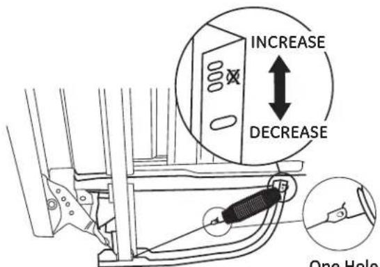
text_image
INCREASE DECREASE One HoleFigure H
Type 2 - Three-hole cable
Adjust tension by moving spring hook to one of the three holes on the pulley cable.
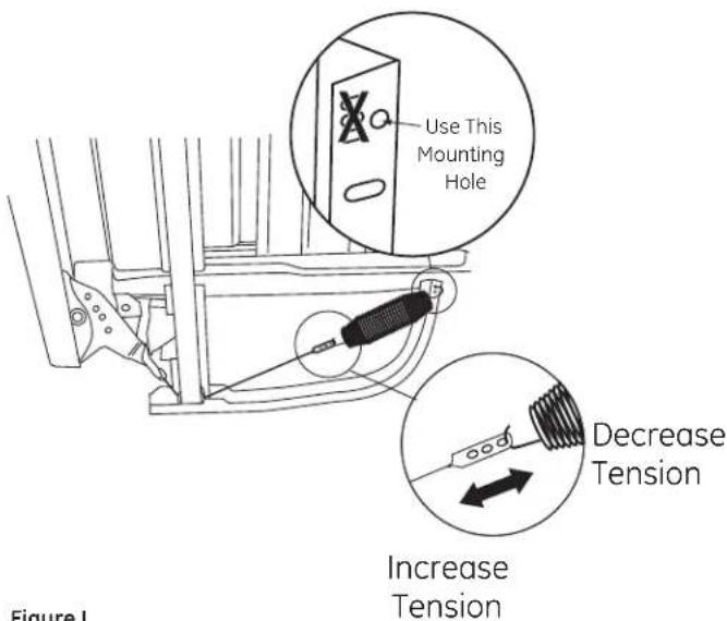
text_image
Use This Mounting Hole Decrease Tension Increase Tension Figure 1Figure I
After adjusting spring tension, open and close the door to make sure the door operates smoothly. If the door is hard to move or if the spring cable binds, check the routing of the spring cable. The cable should be routed between the shoulders of the pulley cable roller. If the cable is off the roller: latch door, remove spring tension and route the cable between the shoulders of the roller. See Figure J.
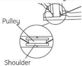
text_image
Pulley ShoulderFigure J
Incorrect Spring Cable Routing
STEP 4 - REMOVE WOOD BASE, INSTALL LEVELING LEGS
IMPORTANT – Do not kick off wood base! Damage will occur.
- Move the dishwasher close to the installation location and lay it on its back.
- Remove the four leveling legs on the underside of the wood base with an adjustable wrench or 15/16" socket.
- Discard base.
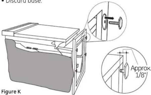
text_image
Discard base. Approx. 1/8" Figure K- Screw leveling legs back into the dishwasher frame approximately 1/8" from frame as shown.
STEP 5 - REMOVE TOEKICK
- Remove the 2 toekick screws and toekick.
Set aside for use in Step 23.
Figure L

text_image
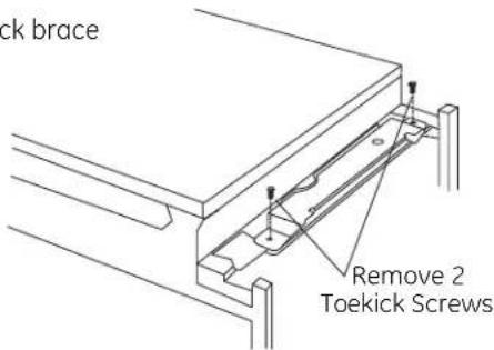
REMOVE TOEKICK toekick screws Remove 2 Toekick ScrewsSTEP 6 - REMOVE TOEKICK BRACE
Skip this step if your model does not have a sound upgrade kit. If your model does have a sound upgrade kit, this brace must be removed.
- Remove the 2 toekick brace
screws and toekick brace. Discard brace and set screws aside for use in Step 22.
Figure M
text_image
ck brace Remove 2 Toekick ScrewsSTEP 7 - INSTALL POWER CORD
Skip this step if dishwasher will be permanently connected to the house electrical system.
In this step you will need the junction box cover and the #10 x 1/2" hex-head screw from the screw kit set aside in Step 1.
The power cord and connections must comply with the National Electrical Code, Section 422 and/or local codes and ordinances. Maximum power cord length is 6 feet. Power Cord Kit WX09X70910, available for purchase from an authorized GE Appliance Dealer, meets these requirements.

text_image
Ground White Black Figure N• Install strain relief in junction box bracket.
- Insert power cord through strain relief and tighten.
- Make sure black, white and green dishwasher wires are threaded through small hole in junction box bracket.
- Connect like-colored dishwasher and power cord wires. If power cord wires are not color-coded, connect the ribbed power cord wire to the white dishwasher wire, the smooth power cord wire to the black dishwasher wire and the ground to the green dishwasher wire. Use UL-listed wire nuts of appropriate size.
- Install junction box cover set aside in Step 1, using #10 hex-head screw. Be sure wires are not pinched under the cover.
STEP 8 - INSTALL 90° ELBOW
- Wrap 90^ elbow with thread seal tape.
• Install a 90° elbow onto the water valve.

text_image
Front of Dishwasher Water Valve Bracket 90° Elbow Fill Hose Thread Seal Tape Figure O- Do not overtighten the 90^ elbow; water valve bracket could bend or water valve fi tting could break.
- Position the end of the elbow to face the rear of the dishwasher.
STEP 9 – POSITION WATER LINE AND HOUSE WIRING
- Position water supply line and house wiring on the floor of the enclosure to avoid interference with base of dishwasher and components under dishwasher.

text_image
5" 4" 5" 4" 6" Water Line House WiringFigure P
STEP 10 - INSTALL DRAIN HOSE TO DISHWASHER DRAIN PORT
In this step you will need the drain hose and clamp set aside in Step 1.
- Stand dishwasher upright,
- Place drain hose clamp over 1-3/16" inside diameter end of drain hose with the clamp screw positioned on the bottom of the hose.
IMPORTANT – Prevent drain hose damage and possible leaks. Be careful not to nick or cut the drain hose.
- Push the end of the drain hose over the drain pump outlet being careful not to disturb the check valve. Refer to Figure Q.
- Seat the drain hose end against the hose stops on the pump outlet.
- Position hose clamp against the front lip of the drain hose and tighten clamp.
NOTE: Drain hose supplied with dish - washer is approximately 78" long. If a longer hose is needed, a 120" long hose (10 feet) may be purchased from an authorized GE appliance dealer. The 10' long hose is part number GPF10L.
Figure Q

text_image
n hose with dish - oproxi- ong. hose is 20" long let) may ed from ed e Pump Outlet Hose Stop Hose Clamp Check Valve Do Not RemoveTip: Avoid unnecessary service charges. Make a leak free connection
Insert hose against stop on pump. Position clamp against front lip of drain hose with clamp screw on bottom side of hose. Tighten clamp to at least 15 inch-pounds of torque.
Tip: Reduce drain pump noise
Position drain hose clamp so screw is on the bottom side of the hose. This will prevent noise caused by the clamp coming in contact with the tub bottom. Refer to Figure Q.
STEP 11 - INSERT DRAIN HOSE THROUGH CABINET
- Position dishwasher in front of cabinet opening. Insert drain hose into the hole in cabinet side. If a power cord is used, guide the end through a separate hole.
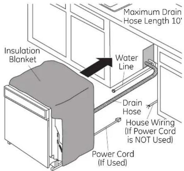
text_image
Maximum Drain Hose Length 10' Insulation Blanket Water Line Drain Hose House Wiring (If Power Cord is NOT Used) Power Cord (If Used)Figure R
Tip: Position water line and house wiring on the floor to avoid interference with base of dishwasher.
STEP 12 - SLIDE DISHWASHER THREE-FOURTHS OF THE WAY INTO CABINET
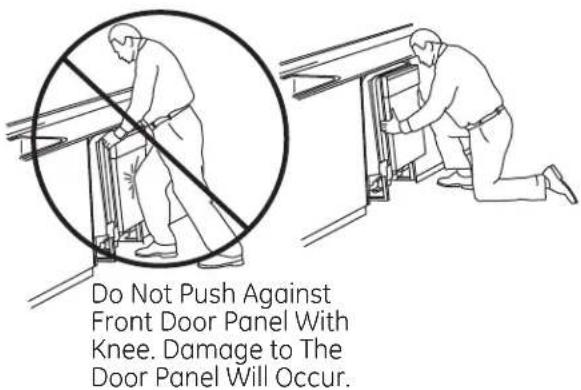
IMPORTANT – DO NOT PUSH AGAINST FRONT PANEL WITH KNEES. DAMAGE WILL OCCUR.
- Grasp the dishwasher by its sides and slide it into the opening a few inches at a time.
text_image
Do Not Push Against Front Door Panel With Knee. Damage to The Door Panel Will Occur.Figure S
- As you proceed, pull the drain hose through the opening under the sink. Stop pushing when the front of the dishwasher is a few inches forward of adjacent cabinets. - Make sure drain hose is not kinked under the dishwasher and there is no interference with the water line, wiring or any other component.
Tip: Make sure the dishwasher will fit in the cabinet. Check to be sure the power cable, drain hose and hot water line are not trapped behind the dishwasher. Utility lines trapped behind the dishwasher prevent the dishwasher from being pushed fully into the enclosure.
STEP 13 - SLIDE DISHWASHER INTO FINAL POSITION
- Push the dishwasher the rest of the way into the cabinet.
- Push the sides with your hands. Do not push the dishwasher with your knee, as this will damage the door.
- Check that the tub insulation blanket does not get "bunched up" or interfere with the springs as you slide it into the cabinet.
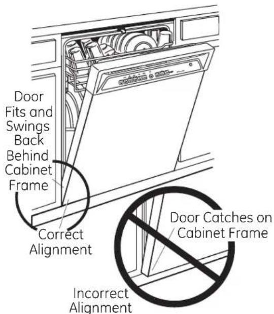
• Center the dishwasher in the opening. - Front of door panel should be flush with face of cabinet.
- Carefully open and close the door to ensure that the door panel does not catch or rub on the cabinet frame. Refer to Figure U below.
- If the door catches or rubs on the frame, reposition and/or level the unit (see Step 14) until the door moves freely and does not contact the cabinet frame.
text_image
Door Fits and Swings Back Behind Cabinet Frame Correct Alignment Incorrect Alignment Door Catches on Cabinet FrameFigure U
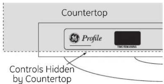
Special Considerations for Positioning Top-Mount Control Models
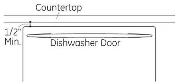
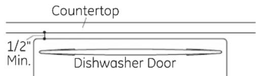
The controls on these models are designed to be hidden by your countertop. Align the dishwasher as shown in Figure V. Leave a 1/2" minimum gap between the underside of the countertop and the top of the dishwasher door as shown in Figure W.
Use the leveling legs to increase or decrease the amount of gap between the controls and the countertop.
For flush installations of the custom panel models, it may be necessary to cut off the back panel of the tub insulation blanket so that the dishwasher door panel can be aligned with the kitchen cabinet panels.
IMPORTANT – Leave a 1/2" minimum gap between the controls and the underside of the countertop to prevent condensation and damage to the control panel from screw heads.
text_image
Countertop Profile TIME REMAINING Controls Hidden by CountertopFigure V
text_image
Countertop 1/2" Min. Dishwasher DoorFigure W
STEP 14 - LEVEL DISHWASHER
IMPORTANT – Dishwasher must be level for proper dish rack operation and wash performance.
- For Top-Mount Control Models:
Make sure 1/2" minimum gap is maintained.
- For All Models:
Place level on door to check that the dishwasher is level side to side. Remove lower
rack, place level on lower rack track inside tub to check that the dishwasher is level front to back.
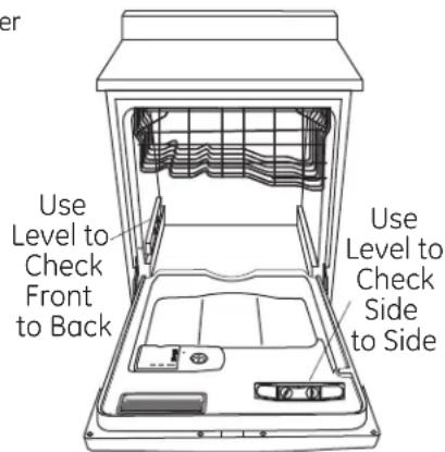
text_image
Use Level to Check Front to Back Use Level to Check Side to SideFigure X
- If the dishwasher is not level, adjust the four leveling legs as illustrated in Figure Y.
- If adjustment to the right-rear leveling leg is required, access it by loosening the junction box bracket screw (through the access hole) and rotate bracket clockwise.
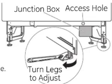
text_image
Junction Box Access Hole Turn Legs to AdjustFigure Y
- The dishwasher is properly leveled when the level indicator is centered left to right and front to back. The dishwasher door should close without hitting the sides of the tub,
- Replace the lower rack when leveling is complete.
Tip: Avoid unnecessary service charges for poor wash performance and rack operation.
Pull the dish racks half way out. They should remain stationary. Open and close the door. The door should fit in the tub opening without hitting the side of the tub. If the racks roll on their own, or the door hits the side of the tub, relevel the dishwasher.
IMPORTANT - After leveling, verify that the dishwasher is centered in the enclosure and the door does not hit adjacent cabinets.
STEP 15 - SECURE DISHWASHER TO COUNTERTOP OR CABINET
In this step you will need the 2 Phillips special head screws set aside in Step 1.
The dishwasher must be secured to the countertop or the cabinet sides. When countertops are made of wood, use Method 1. When countertops are granite or other materials that will not accept screws, use Method 2 to secure dishwasher at the sides.

text_image
Side-Mounting Brackets Tub Frame Countertop Mounting BracketsFigure Z
IMPORTANT -
Avoid unnecessary service charges.
Drive screws straight and flush. Protruding screw heads will scratch the top or sides of the control
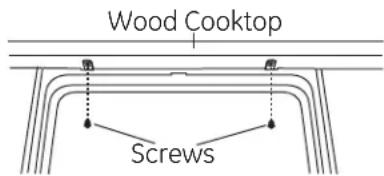
text_image
Wood Cooktop ScrewsFigure AA
panel and can interfere with door closing.
Method 1
Secure dishwasher to wood countertop
- Fasten the dishwasher to the underside of the countertop with the 2 Phillips special head screws provided.
Method 2
Secure dishwasher with side-mounting brackets
- Remove plug buttons (one on each side).
- Install screws through the dishwasher side-mount bracket and into the adjacent cabinet on each side. Reinstall plug buttons.
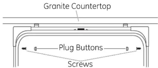
text_image
Granite Countertop Plug Buttons ScrewsFigure BB
Either Method-For Top-Mount Control Models. Make certain 1/2" gap minimum is maintained.
- When step is complete, close dishwasher door and verify that gap between countertop and top of dishwasher door is at least 1/2" .
text_image
Countertop 1/2" Min. Dishwasher DoorFigure CC
STEP 16 - CONNECT WATER SUPPLY
Connect water supply line to the 90° elbow.
- Slide compression nut, then ferrule over end of water line.
- Insert water line into 90^ elbow.
- Slide ferrule against elbow and secure with compression nut.
IMPORTANT – Check to be sure that door spring does not rub or contact the fill hose or water supply line. Test by opening and closing the door. Reroute the lines if a rubbing noise or interference occurs.
Figure DD

text_image
Compression Nut Ferrule 90° Elbow Hot Water Supply Line 90° Elbow Door SpringSTEP 17 - CONNECT DRAIN LINE
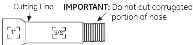
The molded end of the drain hose will fit 5/8" through 1" diameter inlet ports on the air gap, waste tee or disposer.
• Determine size of inlet port
- Cut drain hose connector on the marked line, if required, to fit the inlet port.
text_image
Cutting Line IMPORTANT: Do not cut corrugated portion of hose 1" 5/8"Figure EE
- If a longer drain hose is required, and you did not purchase 10' long GPF10L drain hose, add up to 3-1/2' of length for a total of 10' to the factory-installed hose. Use 5/8" or 7/8" inside diameter
hose and a coup to connect the two hose ends. Secure the connection with hose clamps.
Figure FF

text_image
Hose Clamp Coupler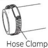
NOTE: TOTAL DRAIN HOSE LENGTH MUST NOT EXCEED 10' FOR PROPER DRAIN OPERATION.
DRAIN LINE INSTALLATION
- Connect drain line to air gap, waste tee or disposer using the previously determined method.
- Secure the drain hose to the air gap, waste tee or disposer with clamps.
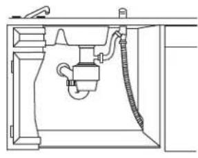
Method 1 – Air gap with waste tee or disposer Insert the drain hose into the air gap as shown.

natural_image
Technical line drawing of a mechanical assembly with pipes and tubing (no text or symbols)Waste Tee Installation Figure GG
natural_image
Technical line drawing of a mechanical or plumbing component inside a cabinet (no text or symbols)Disposer Installation
Method 2 – High Drain Loop with the Waste Tee or Disposer Route the drain hose of the dishwasher to a minimum height of 32" from the floor with the supplied hanger as shown.

text_image
18" Min. 32" Min.Waste Tee Installation Figure HH

text_image
32" 18" Min. Min.Disposer Installation
IMPORTANT – One of the above methods must be used or dishwasher will not operate properly.
IMPORTANT - When connecting drain line to disposer, check to be sure that drain plug has been removed. DISHWASHER WILL NOT DRAIN IF PLUG IS LEFT IN PLACE.
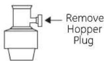
Tip: Avoid unnecessary service call charges. Always be sure disposer drain plug has been removed before attaching dishwasher drain hose to the disposer.
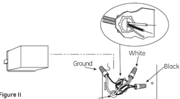
STEP 18 - CONNECT POWER SUPPLY
Skip this step if dishwasher is equipped with power cord. Verify that power is turned off at the source.
- Locate junction box cover set aside in Step 1.
- Secure house wiring to the back of the junction box with a strain relief.
- Locate the three dishwasher wires, (white, black and green) with stripped ends. Insert dishwasher wires through the small hole in the junction box. Connect like-colored dishwasher and power cable wires using UL-listed wire nuts of appropriate size.
- Install the junction box cover. Check to be sure that wires are not pinched under the cover.
text_image
Figure II Ground White BlackFigure II
WARNING

iring is not 2-wire with a ground und must be provided by the installer.
se wiring is aluminum, be sure -listed anti-oxidant compound num-to-copper connectors.
ADVERTENCIA

Review this list after installing your dishwasher to avoid charges for a service call that is not covered by your warranty.
☐ Check to be sure power is OFF.
Open door and remove all foam and paper packaging.
Locate the Owner's Manual set aside in step 1.
Read the Owner's Manual for operating instructions.
☐ Check door opening and closing. If door does not open and close freely, check for proper routing of spring cable over pulley. If door drops or closes when released, adjust spring tension. See Step 3, Figure J.
☐ Check to be sure that wiring is secure under the dishwasher, not pinched or in contact with door springs or other components. See Step 9.
☐ Check door alignment with tub. If door hits tub, level dishwasher. See Step 14.
☐ Pull lower rack out, about halfway. Check to be sure it does not roll back or forward on the door. If the rack moves, adjust leveling legs. See Step 14.
☐ Check door alignment with cabinet. If door hits cabinet, reposition or relevel dishwasher. See Steps 13, 14 and 15.
☐ Check that door spring does not contact water line, fill hose or other components. See Step 16.
Verify water supply and drain lines are not kinked or in contact with other components. Contact with motor or dishwasher frame could cause noise. See Steps 9 and 11.
Turn on the sink hot water faucet and verify water temperature. Incoming water temperature must be between 120°F and 150°F. A minimum of 120°F temperature is required for best wash performance. See "Prepare Hot Water Supply," page 6.
☐ Add 2 quarts of water to the bottom of the dishwasher to lubricate the pump seal.
Turn on water supply. Check for leaks. Tighten connections if needed.
☐ Remove protective film if present from the control panel and door.
☐ Avoid service call charges by ensuring there is an air gap or drain hose routed through the required 32" minimum height.
STEP 20 - DISHWASHER WET TEST
Turn on power supply (or plug power cord into outlet, if equipped).
Start the unit to check for leaks.
Front-Mount Control Models:
- Close & latch door
- Push RINSE ONLY pad
- Push START/RESET pad one time
Top-Mount Control Models:
- Push RINSE ONLY pad
- Push START/RESET pad one time
- Close & latch door
Check to be sure that water enters the dishwasher. If water does not enter the dishwasher, check to be sure that water and power are turned on.
Check for leaks under the dishwasher. If a leak is found, turn off power supply, then tighten connections. Restore power after leak is corrected.
Check for leaks around the door. A leak around the door could be caused by door rubbing or hitting against adjacent cabinet. Reposition the dishwasher if necessary. See Steps 13, 14 and 15.
The dishwasher will drain and turn off about 5 minutes after it was started. Check drain lines. If leaks are found, turn off power supply and correct plumbing as necessary. Restore power after corrections are made. See Step 10 and 17.
Open dishwasher door and make sure most of the water has drained. If not, check to be sure disposer plug has been removed and/or air gap is clear. See Step 17. Also check drain line to be sure it is not kinked.
Run the dishwasher through another "Rinse Only" cycle. Check for leaks and correct if required.
STEP 21 - Set Water Hardness
Models with bulk dispenser only. Skip this step if your dishwasher does not have the bulk dispense feature.
- Locate the hard water test strip set aside in Step 1.
- Remove strip from package.
- Turn on the hot water and hold the strip under the stream, following the directions on the package.
- Use the value on the test strip to calibrate your dishwasher for water hardness. Refer to the section titled "Water Hardness Calibration" in your Owner's Manual for information on how to calibrate your dishwasher.
STEP 22 - INSTALL SOUND UPGRADE KIT IF EQUIPPED
Skip this step if your model does not have the Sound Upgrade Kit.
- Locate sound upgrade kit set aside in Step 1 and the two screws set aside in Step 6.
- Attach the plastic Sound Panel as shown in Figure LL using the two screws. The lower set of mounting holes should be used.
- Be sure the sound panel is seated in the notches on frame as shown in Figure JJ.

text_image
Sound panel is located under door panel. Plastic Sound Panel with Foam Attachment Screws Be sure that the sound panel is seated in the notch in the frame. (Both sides)Figure JJ
STEP 23 - INSTALL TOEKICK
- Locate toekick and screws set aside in step 5.
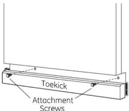
text_image
Toekick Attachment ScrewsFigure KK
- Replace the toekick and make sure it is against the floor.
- Insert and tighten the 2 toekick attachment screws. The toekick should stay in contact with the floor to ensure quiet dishwasher operation.
STEP 24 - LITERATURE
- Be sure to leave complete literature package, Installation Instructions and product samples with the consumer.
SPECIFICATIONS SUBJECT TO CHANGE WITHOUT NOTICE
GE Consumer & Industrial
General Electric Company
Louisville, Kentucky 40225
natural_image
Line drawing of a kitchen appliance with a large front door open, showing internal compartments and wheels (no text or symbols)LIRE ATTENTIVEMENT.
IL FAUT GARDER CES INSTRUCTIONS.
PIÈCES FOURNIES AVEC LE KIT
D'INSTALLATION :
natural_image
Technical line drawing of a mechanical or plumbing assembly with pipes and fixtures (no text or symbols)natural_image
Technical line drawing of a mechanical assembly or fixture (no text or symbols)text_image
Figure N Terre Blanc Noirnatural_image
Technical line drawing of a mechanical or electrical component with pipes and housing (no text or symbols)natural_image
Technical line drawing of a shared sink with internal piping and valve (no text or labels)General Electric Company
Louisville, Kentucky 40225


