38XRA - Multimeter Amprobe - Free user manual and instructions
Find the device manual for free 38XRA Amprobe in PDF.

Frequently Asked Questions - 38XRA Amprobe
User questions about 38XRA Amprobe
0 question about this device. Answer the ones you know or ask your own.
Ask a new question about this device
Download the instructions for your Multimeter in PDF format for free! Find your manual 38XRA - Amprobe and take your electronic device back in hand. On this page are published all the documents necessary for the use of your device. 38XRA by Amprobe.
USER MANUAL 38XRA Amprobe
Limited Warranty and Limitation of Liability
Your Amprobe product will be free from defects in material and workmanship for one year from the date of purchase unless local laws require otherwise. This warranty does not cover fuses, disposable batteries or damage from accident, neglect, misuse, alteration, contamination, or abnormal conditions of operation or handling. Resellers are not authorized to extend any other warranty on the behalf of Amprobe. To obtain service during the warranty period, return the product with proof of purchase to an authorized Amprobe Service Center or to an Amprobe dealer or distributor. See Repair Section for details. THIS WARRANTY IS YOUR ONLY REMEDY. ALL OTHER WARRANTIES - WHETHER EXPRESS, IMPLIED OR STATUTORY - INCLUDING IMPLIED WARRANTIES OF FITNESS FOR A PARTICULAR PURPOSE OR MERCHANTABILITY, ARE HEREBY DISCLAIMED. MANUFACTURER SHALL NOT BE LIABLE FOR ANY SPECIAL, INDIRECT, INCIDENTAL OR CONSEQUENTIAL DAMAGES OR LOSSES, ARISING FROM ANY CAUSE OR THEORY. Since some states or countries do not allow the exclusion or limitation of an implied warranty or of incidental or consequential damages, this limitation of liability may not apply to you.
Repair
All Amprobe returned for warranty or non-warranty repair or for calibration should be accompanied by the following: your name, company's name, address, telephone number, and proof of purchase. Additionally, please include a brief description of the problem or the service requested and include the test leads with the meter. Non-warranty repair or replacement charges should be remitted in the form of a check, a money order, credit card with expiration date, or a purchase order made payable to Amprobe.
In-Warranty Repairs and Replacement – All Countries
Please read the warranty statement and check your battery before requesting repair. During the warranty period, any defective test tool can be returned to your Amprobe distributor for an exchange for the same or like product. Please check the "Where to Buy" section on amprobe.com for a list of distributors near you. Additionally, in the United States and Canada, in-warranty repair and replacement units can also be sent to an Amprobe Service Center (see address below).
Non-warranty Repairs and Replacement – United States and Canada
Non-warranty repairs in the United States and Canada should be sent to an Amprobe Service Center. Call Amprobe or inquire at your point of purchase for current repair and replacement rates.
USA: Canada:
Amprobe Amprobe
Everett, WA 98203 Mississauga, ON L4Z 1X9
Tel: 877-AMPROBE (267-7623) Tel: 905-890-7600
Non-Warranty Repairs and Replacement – Europe
European non-warranty units can be replaced by your Beha-Amprobe distributor for a nominal charge. Please check the "Where to Buy" section on beha-amprobe.com for a list of distributors near you.
Beha-Amprobe
Division and reg. trademark of Fluke Corp. (USA)
Germany* United Kingdom
In den Engematten 14 52 Hurricane Way
79286 Glottertal Norwich, Norfolk
Germany NR6 6JB United Kingdom
Phone: +49 (0) 7684 8009 - 0 Phone: +44 (0) 1603 25 6662
The Netherlands - Headquarters**
Science Park Eindhoven 5110
5692 EC Son
The Netherlands
Phone: +31 (0) 40 267 51 00
beha-amprobe.com
*(Correspondence only – no repair or replacement available from this address. European customers please contact your distributor.)
**single contact address in EEA Fluke Europe BV
text_image
38XR-A REL FOC P-7 MAX MIN AVE HOLD RANGE MC+02 BANC -8.8.8.8 CHMP 40mA Tenske MC+02 MIN MAX AVE PREL RANGE HOLD RS232 10A OFF H2 μA 30A C F TRUE RMS AC+DC mA μA CAT RE 1000V CAT EX 600V COM 10A 40mA Tenske VQ MAX 10A MAX 10A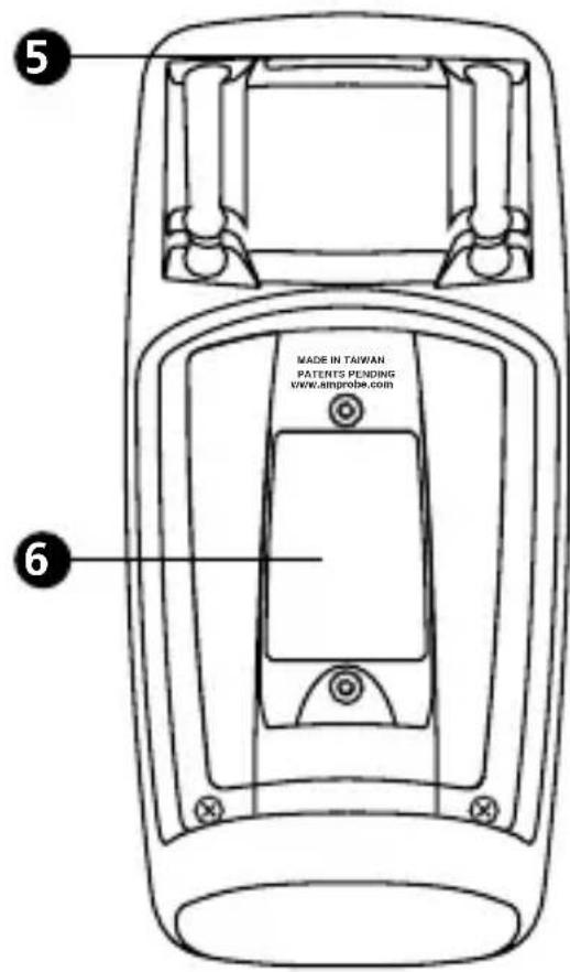
text_image
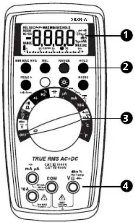
5 MADE IN TAIWAN PATENTS PENDING WWW SIMPROBE.COM 61 Display
② Feature Buttons
3 Function/Range Switch
4 Test Lead Connections
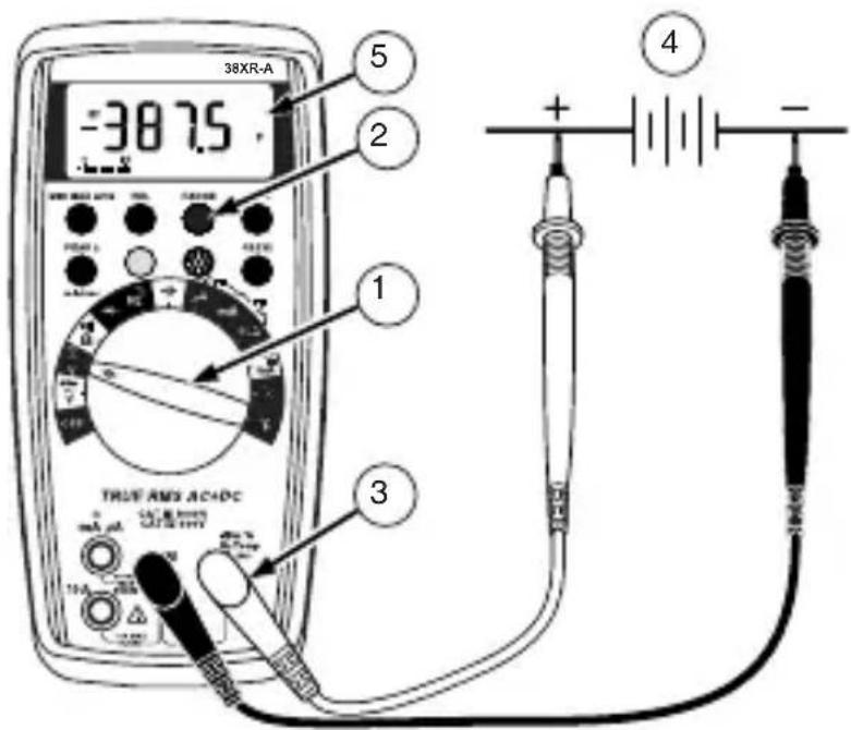
5 Strap Clip
6 Battery/Fuse Cover
CONTENTS
SYMBOLS....2
SAFETY INFORMATION ......2
UNPACKING AND INSPECTION ....3
INTRODUCTION ....4
MAKING MEASUREMENTS 4
ADDITIONAL FEATURES 16
PRODUCT MAINTENANCE....21
SPECIFICATIONS....22
SAFETY....23
ELECTRICAL SPECIFICATIONS....24
SYMBOLS
| Battery | |
| Double insulated | |
| Direct Current | |
| Alternating Current | |
| Fuse | |
| CE | Complies with EU Directives |
| Refer to the Manual | |
| Dangerous Voltage | |
| Earth Ground | |
| Audible tone | |
 | Underwriters Laboratories, Inc. |
| CAT III | MEASUREMENT CAT III is applicable to test and measuring circuits connected to the distribution part of the building's low-voltage mains installation. |
| CAT IV | MEASUREMENT CAT IV is applicable to test and measuring circuits connected at the source of the building's low-voltage mains installation. |
SAFETY INFORMATION

Warning
Do not alter the Product and use only as specified, or the protection supplied by the Product can be compromised.
- The 38XR-A Digital Multimeter is for use with fixed equipment installations, such as, distribution panels, feeders and short branch circuits and lighting systems in large buildings; and for the primary supply level, such as, an electric meter or an overhead or underground utility service.
- Do not exceed the maximum overload limits per function (see specifications) nor the limits marked on the instrument itself. Never apply more than 1000V dc/750 V ac rms between the test lead and earth ground.
- Inspect the DMM, test leads and accessories before every use. Do not use any damaged part.
- Never ground yourself when taking measurements. Do not touch exposed circuit elements or test probe tips.
- Do not operate the instrument in an explosive atmosphere.
- Exercise extreme caution when: measuring voltage >20V // current >10mA // AC power line with inductive loads // AC power line during electrical storms // current, when the fuse blows in a circuit with open circuit voltage >1000 V // servicing CRT equipment.
- Always measure current in series with the load – NEVER ACROSS a voltage source. Check fuse first. Never replace a fuse with one of a different rating.
- Remove test leads before opening the Battery Cover or case.
UNPACKING AND INSPECTION
Your shipping carton should include:
1 38XR-A Digital Multimeter
1 Test leads w/ alligator clips
1 Magne-Grip® Holster
1 Clip, magnet, and strap
1 Temperature Adapter
1 K-type thermocouple
1 Users Manual
1 9 V battery (installed)
1 mA fuse, 0.5A/1000 V
INTRODUCTION
The 38XR-A is a true rms autoranging handheld digital multimeter for measuring or testing the following:
- DC and AC Voltage
- Capacitance
- DC and AC Current
- Diodes
- Resistance
- Continuity
- Frequency
- dBm
- Dutycycle
• 4 - 20 mA Loop Current
- Temperature
Additional features include: MIN MAX AVG, HOLD, REL, PEAK±, Range Lock, RS-232 IR communication, and Backlight.
MAKING MEASUREMENTS
Verify Instrument Operation
Before attempting to make a measurement, verify that the instrument is operational and the battery is good. If the instrument is not operational, have it repaired before attempting to make a measurement.
Range Selection
In addition to autoranging the 38XR-A allows you to manually select and lock a range by pressing the RANGE button. RANGE appears on the display to indicate that manual ranging is active and the range is locked. When appropriate, each subsequent press of the range button steps the meter to the next higher range. When the highest range is reached the next press returns the meter to the lowest range. To return to autoranging press and hold the RANGE button for 2 seconds. If RANGE still shows on the display, autoranging is not appropriate for the selected function.
Use autorange for all initial measurements. Then, when appropriate, use the RANGE button to select and lock a range.

WARNING
To avoid electrical shock while manual ranging use the display annunciators to identify the actual range selected.
Correcting an Overload (OL or - OL) Indication △
An OL or - OL indication may appear on the display to indicate that an overload condition exists. For voltage and current measurements, an overload should be immediately corrected by selecting a higher range. If the highest range setting does not eliminate the overload, interrupt the measurement until the problem is identified and eliminated. The OL indication is normal for some functions; for example, resistance, continuity, and diode test.
Measuring DC Voltage
- Set the Function Switch to .
- If RANGE is displayed, press the RANGE button to enable autoranging.
- Connect the Test Leads: Red to VΩ→, Black to COM
- Connect the Test Probes to the circuit test points.
- Read the display, and, if necessary, correct any overload (OL) conditions.
text_image
38XR-A -38.75 5 2 1 3 TRUE AND ACADC + - -Measuring AC + DC Voltage (True rms)
See Additional Features to find out the advantages of true rms.
- Set the Function Switch to .
- If DC is displayed, press the yellow button to turn on AC+DC.
- If RANGE is displayed, press the RANGE button to enable autoranging.
- Connect the Test Leads: Red to VΩ→+, Black to COM
- Connect the Test Probes to the circuit test points.
- Read the display, and, if necessary, correct any overload (OL) conditions.
Measuring AC Voltage (True rms)
See Additional Features to find out the advantages of true rms.
- Set the Function Switch to .
- If dBm is displayed, press the yellow button to turn on AC.
- If RANGE is displayed, press the RANGE button to enable autoranging.
- Connect the Test Leads: Red to VΩ→+, Black to COM
- Connect the Test Probes to the circuit test points.
- Read the display, and, if necessary, correct any overload (OL) conditions.

text_image
38XR-A 115.1 6 2 3 1 4 TRUE RMS AC+DC VAC/VEY OUT B: 0.0000 M M M M M M M M M M M M M M M M M M M M M M M M M M M M M M M M M M M M M M M M M M M M| Input WaveformSignal d'entréeEingangsschwingungsformForma d'onda d'ingressoForma de onda de entrada | 38XR-ATure rms * | ||
| AC | |||
| AC + DC | |||
| Sine WaveSinusoidaleSinusschwingungOnda sinusoidaleOnda sinusoidal | 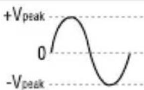 | 0.707 x V_peak CF = 1.414 | |
||
| Full Wave, Sine WaveOnde complète,SinusoidaleVolle Schwingung,SinusschwingungOnda sinusoidale, onda interaOnda completa, Onda sinusoidal | 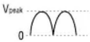 | 0.308 x V_peak CF = 3.247 | |
| 0.707 x V_peak CF = 1.414 | |||
| Half-Wave, Sine WaveDemi-onde, sinusoidaleHalbschwingung,SinusschwingungOnda sinusoidale, semiondaMedia onda, onda sinusoidal | 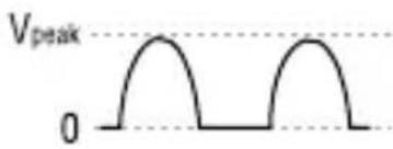 | 0.386 x V_peak CF = 2.591 | |
| 0.500 x V_peak CF = 2.000 | |||
| Square WaveOnde carréeRechteckschwingungOnda quadraOnda cuadrada | 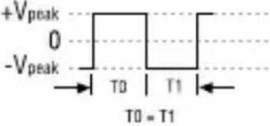 | 1.000 x V_peak CF = 1.000 | |
||
| Square WaveOnde carréeRechteckschwingungOnda quadraOnda cuadrada |  | 0.500 x V_peak CF = 2.000 | |
| 0.707 x V_peak CF = 1.414 | |||
| Pulse WaveOnde impulsionnelleImpulsschwingungOnda dell'impulsoOnda de impulsos | V_pe 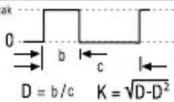 | V_peak x KCF = 1 / K | |
| V_peak x CF = V_peak / | |||
| Sawtooth WaveOnde en dent de scieSägezahnschwingungOnda a denti di segaOnda diente de sierra |  | 0.577 x V_peak CF = 1.733 | |
||
| * CF = Crest Factor, Crest Factor = V_peak / V_rms | |||
Preparing for Current Measurements
- Turn off circuit power before connecting the Test Probes.
- Allow the meter to cool between measurements, if current measurements approach or exceeds 10 amps.
- A warning tone sounds if you connect a test lead to a current input while a current function is not selected.
- Open circuit voltage at the measurement point must not exceed 1000 V.
• Always measure current in series with the load. Never measure current across a voltage source.
Measuring DC Current
- Set the Function Switch to a current function, A , mA, or 10A.
- If AC or AC+DC is displayed, press the yellow button to turn on DC.
- If the A function is selected and RANGE is displayed, press the RANGE button to enable autoranging.
- Connect the Test Leads: Red to mA or 10A, Black to COM.
- Turn off power to the circuit being measured.
- Open the test circuit (—×—) to establish measurement points.
- Connect the Test Probes in series with the load (to the measurement points).
- Turn on power to the circuit being measured.
- Read the display, and, if necessary, correct any overload (OLor - OL) conditions.
text_image
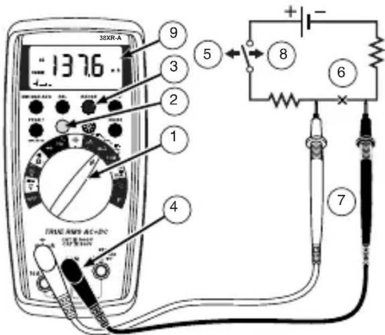
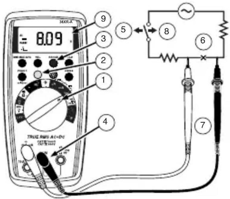
38XR-A 137.6 9 3 2 1 4 5 8 6 7Measuring AC or AC+DC Current (True rms)
See Additional Features to find out the advantages of true rms.
- Set the Function Switch to a current function and range, A, mA, or 10A.
- If DC is displayed, press the yellow button to turn on AC or AC+DC.
- If the A or mA function is selected and RANGE is displayed, press the RANGE button to enable autoranging.
- Connect the Test Leads: Red to mA or 10A, Black to COM
- Turn off power to the circuit being measured.
- Open the test circuit (—×—) to establish measurement points.
- Connect the Test Probes in series with the load (to the measurement points).
- Turn on power to the circuit being measured.
- Read the display, and, if necessary, correct any overload (OL) conditions.
text_image
38XR-A 8.09 9 3 2 1 5 4 TRUE RMS AC-ADC CATE: 100V CATE: 100V 7 6| Input WaveformSignal d'entréeEingangsschwingungsformForma d'onda d'ingressoForma de onda de entrada | 38XR-ATure rms * | |
| AC | ||
| AC + DC | ||
| Sine WaveSinusoidaleSinusschwingungOnda sinusoidaleOnda sinusoidal | 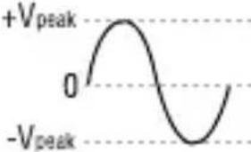 | 0.707 x V_peak CF = 1.414 |
 ||
| Full Wave, Sine WaveOnde complète,SinusoidaleVolle Schwingung,SinusschwingungOnda sinusoidale, onda interaOnda completa, Onda sinusoidal | 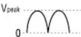 | 0.308 x V_peak CF = 3.247 |
| 0.707 x V_peak CF = 1.414 | ||
| Half-Wave, Sine WaveDemi-onde, sinusoidaleHalbschwingung,SinusschwingungOnda sinusoidale, semiondaMedia onda, onda sinusoidal | 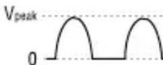 | 0.386 x V_peak CF = 2.591 |
| 0.500 x V_peak CF = 2.000 | ||
| Square WaveOnde carréeRechteckschwingungOnda quadraOnda cuadrada | 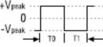 T0 = T1 T0 = T1 | 1.000 x V_peak CF = 1.000 |
| 1.000 x V_peak CF = 1.000 | ||
| Square WaveOnde carréeRechteckschwingungOnda quadraOnda cuadrada | 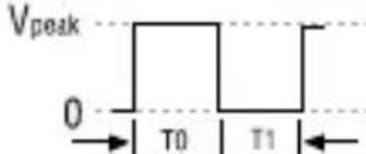 T0 = T1 T0 = T1 | 0.500 x V_peak CF = 2.000 |
| 0.707 x V_peak CF = 1.414 | ||
| Pulse WaveOnde impulsionnelleImpulsschwingungOnda dell'impulsoOnda de impulsos | V_pei 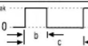 D = b/c K = -D^2 D = b/c K = -D^2 | V_peak × K CF = 1 / K |
| V_peak × CF = V_peak / | ||
| Sawtooth WaveOnde en dent de scieSägezahnschwingungOnda a denti di segaOnda diente de sierra |  | 0.577 x V_peak CF = 1.733 |
 ||
| * CF = Crest Factor, Crest Factor = V_peak / V_rms | ||
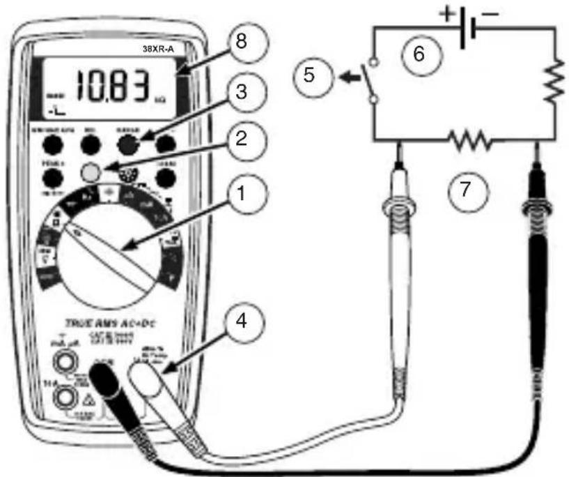
Measuring Resistance
- Set the Function Switch to .
- If 1 is displayed, press the yellow button to display .
- If RANGE is displayed, press the RANGE button to enable autoranging.
- Connect the Test Leads: Red to VΩ→, Black to COM
- Turn off power to the circuit being measured. Never measure resistance across a voltage source or on a powered circuit.
- Discharge any capacitors that may influence the reading.
- Connect the Test Probes across the resistance.
- Read the display. If L appears on the highest range, the resistance is too large to be measured.
text_image
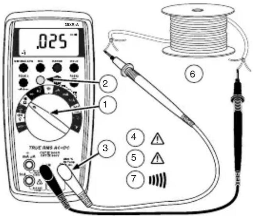
38XR-A 10.83 μΩ 8 3 2 1 5 6 4 TRUE AMS AC+DC 7Testing for Continuity
- Set the Function Switch to "").
- If Ω is displayed, press the yellow button to display "")).
- Connect the Test Leads: Red to VΩ →+, Black to COM
- Turn off power to the circuit being measured.
- Discharge any capacitors that may influence the reading.
- Connect the Test Probes across the resistance.
- Listen for the tone that indicates continuity (< 40 Ω).
text_image
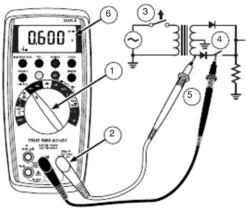
38XR-A .025 -1 2 1 3 4 5 6 TRUE RMS AC+DC TAXI SENS TAXI SENS 7Testing Diodes
- Set the Function Switch to ▶.
- Connect the Test Leads: Red to VΩ→+, Black to COM
- Turn off power to the circuit being measured.
- Free at least one end of the diode from the circuit.
- Connect the Test Probes across the diode.
- Read the display. A good diode has a forward voltage drop of about 0.6 V. An open or reverse biased diode will read ☐L.
text_image
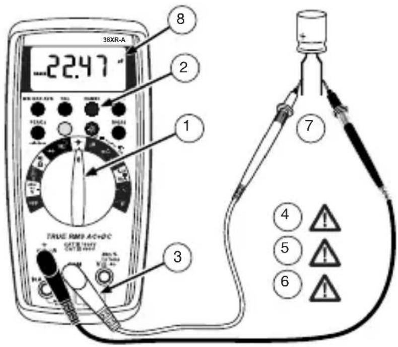
38XR-A 0.600 1 2 3 4 5 TRUE RMS AC+DC mΩ PA SATE B: 100V SATE B: 100V TURB TURB TURB TURB TURB TURB TURB TURB TURB TURB TURB TURB TURB TURB TURB TURB TURB TURB TURB TURB TURB TURB TURB TURB TURB TURBN TURBN TURBN TURBN TURBN TURBN TURBN TURBN TURBN TURBN TURBN TURBNMeasuring Capacitance
- Set the Function Switch to the function.
- If RANGE is displayed, press the RANGE button to enable autoranging.
- Connect the Test Leads: Red to COM, Black to mA
- Turn off power to the circuit being measured.
- Discharge the capacitor using a 100 kΩ resistor.
- Free at least one end of the capacitor from the circuit.
- Connect the Test Probes across the capacitor. When measuring an electrolytic capacitor match the test lead polarity to the polarity of the capacitor.
- Read the display.
text_image
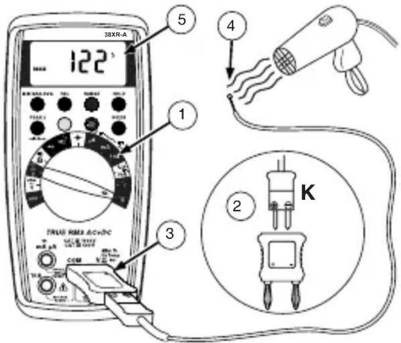
38XR-A 22.47 8 2 1 TRUE RMS ACHOC 3 7 4 5 6Measuring Temperature
- Set the function Switch to °C or °F.
- Connect the K-type thermocouple to a TEMP adapter (XR-TA). Match the polarity of the adapter to the polarity of the thermocouple.
-
Connect the TEMP adapter to the VΩ → and COM inputs. Note: The 38XR-A is compatible with all K-type thermocouples. The K-type bead thermocouple supplied with the meter is not intended for contact with liquids or electrical circuits.
-
Expose the thermocouple to the temperature to be measured.
- Read the display.
text_image
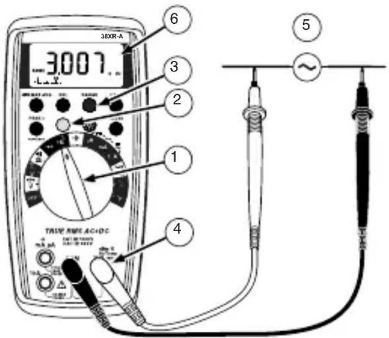
38XR-A 122 5 4 1 TRUE RMS AC+DC 3 K 2Measuring Frequency
- Set the Function Switch to Hz.
- If % is displayed, press the yellow button to display Hz.
- If RANGE is displayed, press the RANGE button to enable autoranging.
- Connect the Test Leads: Red to Hz, Black to COM.
- Connect the Test Probes to the signal source.
- Read the display.
text_image
38XR-A 3007 6 3 2 1 4 TRUE SPEC AC-DC ~Measuring Dutycycle
- Set the Function Switch to %.
- If Hz is displayed, press the yellow button to display %.
- Connect the Test Leads: Red to %, Black to COM.
- Connect the Test Probes to the signal source.
- Read the display.

text_image
38XR-A 20 5 2 1 3 TUNIEN RAMES A/C+DC 20% 100% 4Measuring dBm
The 38XR-A measures dBm relative to 1 mW referenced to 50 Ω. That is, 10 dBm = 10 mW, 0 dBm = 1 mW, -10 dBm = 0.1 mW, etc.
- Set the Function Switch to ^dBm
- Press the yellow button. The display shows dBm to verify the selection.
- Connect the Test Leads: Red to VΩ→, Black to COM.
- Connect the Test Probes to the signal source.
- Read the display.
text_image
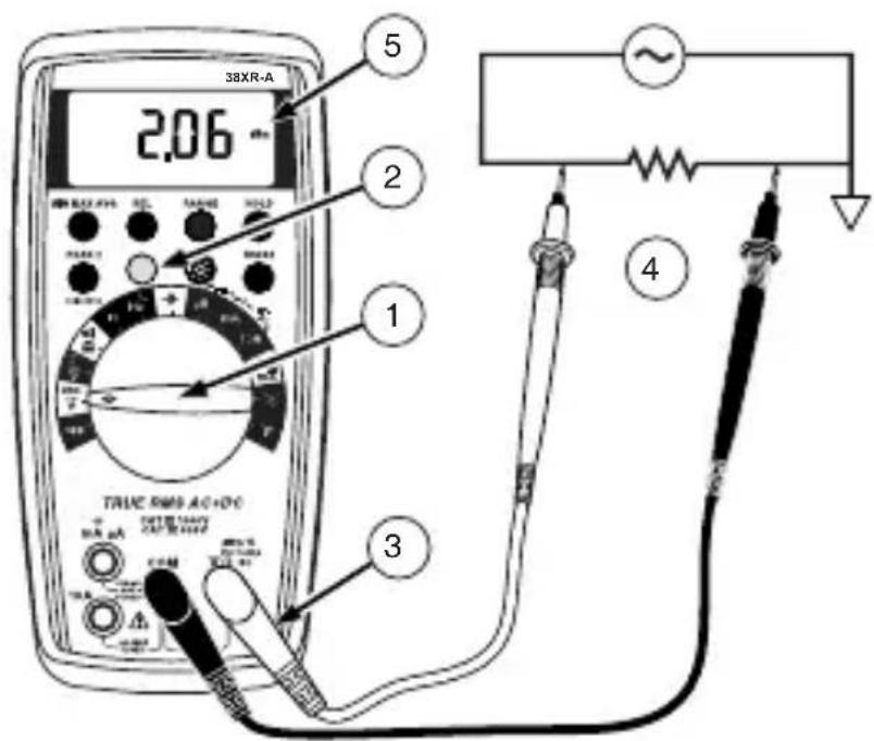
38XR-A 2.06 5 2 1 3 TRUE RMS AC+DC TRELLIANT OUTRANGE 4Measuring 4-20 mA Loop Current
- Set the Function Switch to the loop-current function, 4-20mA .
- Connect the Test Leads: Red to mA, Black to COM.
- Turn off power to the circuit being measured.
- Open the test circuit (—X—) to establish measurement points.
- Connect the Test Probes in series with the load (to the measurement points).
- Turn on power to the circuit being measured.
- Read the display. 0% = 4 mA, 100% = 20 mA.
ADDITIONAL FEATURES
Input Test Lead Warning
The meter emits a continuous tone when a test lead is placed in the mA or 10A input jack and the Function/Range Switch is not set to a correct current position. (If the meter is connected to a voltage source with leads connected for current, very high current could result). All current ranges are protected by fast acting fuses.
True-rms Measurements
For ac measurements most DMMs average the ac input signal and display the result as an estimated rms value. This average-responding method is accurate for sinusoidal waveforms, but can be very inaccurate for distorted waveforms. To ensure the most accurate measurements, always use a true-rms DMM when measuring ac voltage or ac current on circuits for the following kinds of applications:
• Power Supplies - diodes
- Controllers
• Power Limiting - SCR or Triac
- Starting - motors
- Florescent Lighting - ballasts
• Speed Control - motors
- Pulsed Signals
- Any non-sinusoidal ac waveform
The 38XR-A displays the dc, ac, or ac+dc components of a voltage or current measurement. The dc component is the shift level or baseline. The ac component is the area under the waveshape. The ac+dc component is the combined effect of the ac and dc components.
MIN MAX AVG Measurements
Note: The MIN MAX AVG feature does not work the dBm nor the dutycycle function.
The MIN MAX AVG feature reads and updates the display to show the maximum, minimum, or average value measured after you press the MIN MAX AVG button.
Pressing the MIN MAX AVG button for less than 1 second will put the meter into a mode of displaying the maximum, minimum, average, or actual readings. Each time the button is pressed, the meter will cycle to the next display mode as shown in the table below. Press the MIN MAX AVG button for more than 2 seconds to disable this feature.
| Button Display Value Displayed | ||
| < 1 second REC MAX | Maximum value after feature activated | |
| REC MIN | Minimum value after feature activated | |
| < 1 second REC AVG | Average value after feature is activated | |
| < 1 second REC | Actual reading, min max being recorded | |
| >2 seconds Exit MIN MAX AVG | Normal measurement, actual reading | |
Peak Hold Measurements
Note: The peak hold feature calibrates itself to meet the specifications.
The function of the peak hold feature is to record and store the positive and negative peak values that occur while measuring ac current or ac voltage. To enable the peak hold feature press the PEAK ± button for more than 2 seconds. The display will show CAL to indicate the calibration cycle is in process. After the CAL indication clears, press the PEAK ± button again to display the maximum (P+) value for the ac voltage or ac current being measured. The display will toggle between the P+ and P- readings each time the PEAK ± button is pressed. Press the PEAK ± button for more than 1 second to exit the PEAK function.
Beeper Off
The beeper is an aural indicator to identify when the DMM is performing a function, making a range change, detecting a limit, and so on. To disable the beeper use the following procedure:
- Set the Function Switch to OFF.
-
Press and hold the HOLD button while turning the Function Switch to the desired function. The no-beep symbol 📂 shows on the display.
-
Release the HOLD button. The beeper feature will remain disabled until the meter is turned off and then on.
Note: To disable both the beeper and Auto Power Off press and hold the REL button while turning on the DMM.
Auto Power Off
Auto Power Off is a battery saving feature that puts the meter into a sleep mode if the Function/Range Switch has not changed position in the last 30 minutes. To wake the meter turn the Function/Range Switch to another position.
The Auto Power Off feature can be disabled to keep the meter from going to sleep. This feature is useful when using the MIN MAX AVG mode for extended periods. To disable the Auto Power Off feature use the following procedure:
- Set the Function Switch to OFF.
- Press and hold the MIN MAX AVG button while turning the Function Switch from OFF to the desired function. The SLEEP OFF message shows on the display.
- Release the MIN MAX AVG button. The Auto Power Off feature will remain disabled until the meter is turned off and then on.
Note: To disable both Auto Power Off and the beeper press and hold the REL button while turning on the DMM.
REL (Relative) Measurements
Note: The REL feature does not work with the dBm or the dutycycle function.
The Relative mode displays the difference between the actual reading and a reference value. It may be used with any function or range. To make a relative measurement first establish a reference value by measuring a value and then pressing the REL button after the reading has stabilized. This stores the measured value as the reference and sets the display to zero. The meter subtracts the reference value from subsequent measurements and displays this difference as the relative value. Measurement values greater than the reference value will be positive and values less than the reference value will be negative.
To exit the Relative Mode, Press and hold the REL button for 2 seconds.
HOLD Measurements
The HOLD button causes the meter to capture and continuously display a measurement reading. To use the HOLD feature make a measurement, and then, after the reading has stabilized, momentarily press the HOLD button. You can remove the test leads and the reading will remain on the display. Pressing the HOLD button again releases the display.
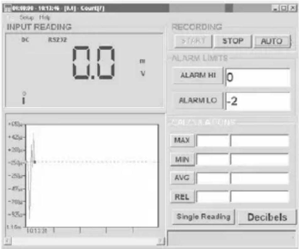
RS232 Download Software (38SW)
The 38XR-A includes an RS232 IR communication port for downloading measurement data (value, function, and range) to a PC. The 38SW Accessory Kit (software and cable) provides a graphical user interface for the PC to collect, store, and display measurement data.
text_image
01:09:30 - 10:13:46 [M] - Court[F] Setup Help INPUT READING DC RS2J2 0.0 m V I RECORDING START STOP AUTO ALARM LIMITS ALARM HI 0 ALARM LO -2 +50µ +42µ +20µ -25µ -25µ -87µ -70µ -52µ 1.15µ 10:13:31 1 CALIFORNIS MAX MIN AVG REL Single Reading DecibelsBacklight
Pressing the ⚙ button illuminates the display with a blue backlight. Pressing the ⚙ button again will turn off the backlight. When turned on the backlight will automatically turn off in about 60 seconds. Frequent use of the backlight will noticeably decrease battery life.
Cleaning
To clean the meter, use a soft cloth moistened with water. To avoid damage to the plastic components do not use benzene, alcohol, acetone, ether, paint thinner, lacquer thinner, ketone or other solvents to clean the meter.
Troubleshooting
If the meter appears to operate improperly, check the following items first.
- Review the operating instructions to ensure the meter is being used properly.
- Inspect and test the continuity of the test leads.
- Make sure the battery is in good condition. The low battery symbol 🔊 appears when the battery falls below the level where accuracy is guaranteed. Replace a low-battery immediately.
- Check the condition of the fuses if the current ranges operate incorrectly.
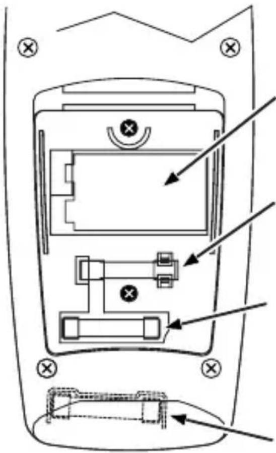
Battery and Fuse Replacement

WARNING
To avoid electrical shock remove the test leads from both the meter and the test circuit before accessing the battery or the fuses.
To access the battery and the mA fuse remove the two screws holding the Battery/Fuse Cover in place, and lift the cover from the meter.
To replace the mA fuse, pry it from its clips using a small screwdriver. A spare mA fuse is located between the battery and the mA fuse.
mA Fuse: Fast Blow .5A/1000V, minimum interrupt rating 30 kA (6.3 x 32 mm) (Amprobe® FP500)
To replace the 10 A fuse: 1) Remove the battery. 2) Remove the four rear-case screws. 3) Separate the case. 4) Remove the 10 A fuse cover. 5) Remove and replace the 10A fuse. 6) Re-install the fuse cover. 7) Reassemble the meter.
10A Fuse: Fast Blow 10A/1000V, minimum interrupt rating 30 kA (10 x 38 mm) (Amprobe® FP100).
text_image
Technical diagram of a mobile phone rear panel with labeled ports and directional arrows indicating movement or assembly.
9 V Battery
Pile 9 V
9 V Batterie
Pila de 9 V
Batería de 9 V
Spare 500 mA fuse
Fusible 500 mA de rechange
| Display | 43⁄4 digit liquid crystal display (LCD) (9999 count) with a 41-segment analog bar-graph. |
| Auto ranging 9999 counts. | |
| Manual ranging 9999 counts. | |
| Polarity | Automatic, positive implied, negative polarity indication. |
| Overrange | OL or - OL is displayed. |
| Zero Automatic. | |
| Low battery indication | The + symbol is displayed when the battery voltage drops below the operating level. |
| Auto power off Approx. 30 minutes. | |
| Measurement rate | 2 times per second, nominal. |
| Operating environment | 0 °C to 50 °C at <70 % R.H. |
| Storage temperature | -20 °C to 60 °C, 0 to 80 % R.H.with battery removed from meter. |
| Temperature Coefficient | 0.1 × (specified accuracy) per °C.(0 °C to 18 °C, 28 °C to 50 °C). |
| Altitude 6562 feet (2000 m) | |
| Power | Single standard 9-volt battery, NEDA 1604, JIS 006P, IEC 6F22. |
| Battery life | 75 hours typical with carbon-zinc.150 hours typical with alkaline. |
| Dimensions 196 mm (H) ×96 mm (W) ×60 mm (D) | |
| Weight Approx. | 492 g including battery. |
SAFETY
General: IEC 61010-1: Pollution Degree 2
Measurement: IEC 61010-2-033: CAT IV 600 V / CAT III 1000 V
IEC 61326-1: Portable Electromagnetic Environment;
IEC 61326-2-2
CISPR 11: Group 1, Class A
Group 1: Equipment has intentionally generated and/or use conductively coupled radio-frequency energy which is necessary for the internal functioning of the equipment itself.
Class A: Equipment is suitable for use in all establishments other than domestic and those directly connected to a low voltage power supply network which supplies buildings used for domestic purposes. There may be
potential difficulties in ensuring electromagnetic compatibility in other environments, due to conducted and radiated disturbances.
Caution: This equipment is not intended for use in residential environments and may not provide adequate protection to radio reception in such environments.
ELECTRICAL SPECIFICATIONS
(Accuracy at 23 °C ±5 °C, <75 % relative humidity)
DC VOLTS
| Ranges | 1000 mV, 10 V, 100 V, 1000 V (auto/manual ranging) |
| Resolution 100 μV | |
| Accuracy ±(0.25 % rdg + 5 dgts) | |
| Input impedance | 10 M Ω |
| Overload protection | 1000 V dc or 750 V ac rms |
AC VOLTS true rms (45 Hz to 2 kHz)
| Ranges | 1000 mV, 10 V, 100 V, 750 V (auto/manual ranging) |
| Resolution 100 μV | |
| Accuracy | ±(1.2 % rdg + 10 dgts) 45 Hz to 500 Hz ±(2.0 % rdg + 10 dgts) 500 Hz to 2 kHz ±(2.0 % rdg + 10 dgts) 45 Hz to 1 kHz on 750 V range |
| Peak Hold accuracy | ±(3.0 % + 200 dgts) on 100 V, 750 V range; 1000 mV, 10 V ranges unspecified |
| Crest Factor ≤ 3 | |
| Input impedance | 10 M Ω |
| AC coupled true rms specified from 5 % to 100 % of range | |
| Overload protection | 1000 V dc or 750 V ac rms |
AC+DC VOLTS (45Hz to 2kHz)
| Ranges | 1000 mV, 10 V, 100 V, 750 V (auto/manual ranging) |
| Resolution 100 μV | |
| Accuracy | ±(1.5 % rdg + 10 dgts) 45 Hz to 500 Hz ±(2.5 % rdg + 10 dgts) 500 Hz to 2k Hz ±(2.5 % rdg + 10 dgts) 45 Hz to 1 kHz on 750 V range |
| Crest Factor ≤ 3 | |
| Input impedance | 10 M Ω |
| Overload protection | 1000 V dc or 750 V ac rms |
| DC coupled true rms specified from 5 % to 100 % of range | |
DC CURRENT
| Ranges | 100 uA, 1000 μA, 10 mA, 100 mA, 400 mA, 10A (auto/manual ranging) |
| Resolution 0.1 μA | |
| Accuracy | ±(0.5 % rdg + 10 dgts) on 100 uA range ±(0.5 % rdg + 5 dgts) on 1000 μA to 400 mA ranges ±(1.5 % rdg + 10 dgts) on 10A range |
| Input impedance | 0.5A/1000V fast blow ceramic fuse 6.3×32mm on μA/mA input 10A/1000V fast blow ceramic fuse 10×38mm on 20A input |
| 10A input | 10 A for 4 minutes maximum followed by a 12 minute cooling period |
| Burden voltage | μA Range: 1 mV/ 1 μAmA Range: 1 mV/ 1 mA10A: 30 mV/ 1 A |
AC CURRENT true rms (AC+DC) (45 Hz to 1 kHz)
| Ranges | 100 uA, 1000 μA, 10 mA, 100 mA, 400 mA, 10A (auto/manual ranging) |
| Resolution 0.1 μA | |
| Accuracy | True rms/±(1.5 % rdg + 20 dgts) on 100 μA to 100 mA ranges True rms/±(2.0 % rdg + 10 dgts) on 400mA range True rms/±(2.5 % rdg + 20 dgts) on 10A range |
| Peak Hold accuracy | ±(3.0 % + 200 dgts) AC coupled true RMS specified from 5 % to 100 % of range AC+DC/±(2.0 % rdg + 20 dgts) on 100 μA to 400 mA ranges AC+DC/±(3.0 % rdg + 20 dgts) on 10A range AC coupled true RMS specified from 10 % to 100 % of range |
| Crest Factor | ≤ 3 |
| Input protection | 0.5A/1000V fast blow ceramic fuse 6.3×32mm on μA/mA input 10A/1000V fast blow ceramic fuse 10×38mm on 10A input |
| 10A input | 10 A for 4 minutes maximum followed by a 12 minute cooling period |
| Burden voltage See DC Current | |
DC CURRENT (4 to 20mA)
| Ranges 0 to 100 % | |
| Accuracy ±0.5 % | + 5 dgt |
| Resolution 0.01 % | |
| Burden voltage 1 | mV/mA |
| Input protection | 0.5A/1000V fast blow ceramic fuse6.3×32mm on μA/mA input |
RESISTANCE
| Ranges | 1000 Ω, 10 kΩ, 100 kΩ, 1000 kΩ, 10 MΩ, 40 MΩ (auto/manual ranging) |
| Resolution 100 m | Ω |
| Accuracy | ±(0.5 % rdg + 8 dgts)on 1000 Ω to 1000 kΩ ranges±(1.0 % rdg +10 dgts) on 10 MΩ range±(2.0 % rdg +10 dgts) on 40 MΩ range |
| Open circuit volts | -0.45 V dc typical |
| Overload protection | 1000 V dc or 750 V ac rms |
CAPACITANCE
| Ranges | 40 nF, 400 nF, 4 μF, 40 μF, 400 uF (3999 counts) (auto/manual ranging) |
| Resolution 0.01 nF | |
| Accuracy | ±(3.0 % rdg +10 dgts)on 40 nF, 400 uF range±(3.0 % rdg +5 dgts)on 400 nF to 40 uF range |
| Test voltange < 1 | V |
| Test Frequency | 1.3 Hz on 40 nF to 40 μF ranges;0.7 Hz on 400 μF range |
| Overload protection | 1000 V dc or 750 V ac rms |
TEMPERATURE
| Ranges | -4 °F to 2372 °F, -20 °C to 1300 °C (3999 counts) |
| Resolution 1 °C, 1 | °F |
| Accuracy | ±(2.0 % rdg + 8 °F) -4 °F to 50 °F±(1.0 % rdg + 6 °F) 50 °F to 400 °F±(2.0 % rdg +4 °F)400 °F to2372 °F±(2.0 % rdg +4 °C) -20 °C to 10 °C±(1.0 % rdg +3 °C)10 °C to 200 °C±(2.0 % rdg + 2 °C) 200 °C to 1300 °C |
FREQUENCY
| Ranges | 100 Hz, 1000 Hz, 10 kHz, 100 kHz, 1000 kHz, 10 MHz, (auto and manual ranging) |
| Resolution 0.1 Hz | |
| Accuracy ±(0.1 % | rdg + 5 dgts) |
| Sensitivity | 3 Hz to 1 MHz: >1.5 V rms; 1 MHz to 10 MHz: >2 V rms, <5 V rms |
| Minimum input range | 100 Hz range >3 Hz 1000 Hz range >30 Hz |
| Minimum pluse width | >25 ns Duty |
| cycle limits >30 % | % and <70 % |
| Overload protection | 1000 V dc or 750 V ac rms |
DUTY CYCLE
| Ranges 0 to 90 % | |
| Resolution 0.01 % | |
| Pulse width >10 μs | |
| Frequency range | 0% to 10% (40 Hz to 20 kHz)10% to 90% (40 Hz to 990 Hz) |
| Accuracy | (5 V logic ) ±(2.0 % rdg + 20 dgts) |
| Overload protection | 1000 V dc or 750 V ac rms |
dBm
| Ranges -13 dBm to +50 dBm | |
| Resolution 0.01 dBm | |
| Accuracy | ±0.7 dB + 8 dgts (45 Hz to 5 kHz) ±2.5 dB + 8 dgts (5 kHz to 10 kHz) |
| Reference impedance | 50 Ω |
| Input protection | 10 MΩ |
| Overload protection | 1000 V dc or 750 V ac rms |
CONTINUITY
| Audible indication | < 40 Ω |
| Response time | 100 ms |
| Overload protection | 1000 V dc or 750 V ac rms |
DIODE TEST
| Test current 0.5 mA (approximate) | |
| Accuracy ±(1.5 % | rdg + 5 dgts) |
| Resolution 1 mV | |
| Open circuit volts | 3.0 V dc typical |
| Overload protection | 1000 V dc or 750 V ac rms |
AUXILIARY FEATURES
| ^ * mA or 10A Test Lead Connection | Beeps to warn test leads are connected to measure current, but the Function/Range Switch is not set to measure current |
| MIN MAX AVG | Displays the minimum, maximum, or average value detected while making a measurement |
| HOLD Holds the latest reading on the display | |
| REL Initiates relative measurements | |
| PEAK± | Record the peak+ or peak- value in a measurement |
| RANGE Initiates manual range mode | |
| Backlight Backlight auto-off approx. 60 seconds | |
| Auto Power off 30 minutes, typical | |
| Shift (yellow button) | Shift to dBm, ac, dc, ac+dc, continuity, duty cycle, or RS232 |
REPLACEMENT PARTS
| TL36 Test Lead Set with Alligator clips | |
| FP500 mA fuse - Fuse Pack .5A/1000V (4 each) | |
| FP100 | 10A fuse - Fuse Pack 10A/1000V(2 each) |
| H2-XR | Magne-Grip® Holster, clip, magnet,and strap |
| XR-TA | Input Adapter for K-typethermocouple |
| TP255 K type thermocouple | |
| 38SW | RS232 Accessory Kit(PC software and cable) |
38XR-A
Professional Digital Multimeter
| Pile | |
| Double isolation | |
| Courant continu | |
| Courant alternatif | |
| Fusible | |
| CE | Conforme aux directives de l’UE |
| Se reporter au mode d’emploi | |
| Tension dangereuse | |
| Prise de terre | |
| Signal sonore | |
 | Underwriters Laboratories, Inc. |
| CAT III | MEASUREMENT CAT III is applicable to test and measuring circuits connected to the distribution part of the building’s low-voltage mains installation. |
| CAT IV | MEASUREMENT CAT IV is applicable to test and measuring circuits connected at the source of the building’s low-voltage mains installation. |
CONSIGNES DE SÉCURITÉ

Avertissement
Do not alter the Product and use only as specified, or the protection supplied by the Product can be compromised.
- The 38XR-A Digital Multimeter is for use with fixed equipment installations, such as, distribution panels, feeders and short branch circuits and lighting systems in large buildings; and for the primary supply level, such as, an electric meter or an overhead or underground utility service.
- Ne pas dépasser les limites de surcharge maximum par
Mesures relatives (REL)
text_image
06:00:00 - 10:12:46 - [M] - Court[F] Setup Help INPUT READING DC RS2JZ 0.0 m V I RECORDING START STOP AUTO ALARM LIMITS ALARM HI 0 ALARM LO -2 CALCULATIONS MAX MIN AVG REL Single Reading DecibelsRétroéclairage
text_image
Technical diagram of a mobile phone rear panel with labeled ports and directional arrows indicating movement or navigation.
9 V Battery
Pile 9 V
9 V Batterie
Pila de 9 V
Batería de 9 V
Spare 500 mA fuse
Fusible 500 mA de rechange
CISPR 11: Group 1, Class A
Group 1: Equipment has intentionally generated and/or use conductively coupled radio-frequency energy which is necessary for the internal functioning of the equipment itself.
Class A: Equipment is suitable for use in all establishments other than domestic and those directly connected to a low voltage power supply network which supplies buildings used for domestic purposes. There may be potential difficulties in ensuring electromagnetic compatibility in other environments, due to conducted and radiated disturbances.
Caution: This equipment is not intended for use in residential environments and may not provide adequate protection to radio reception in such environments.
CARACTÉRISTIQUES ÉLECTRIQUES VOLTS C.C.
| Batería | |
| Aislamiento doble | |
| Corriente continua | |
| Corriente alterna | |
| Fusible | |
| CE | Cumple con las directivas de la Unión Europea |
| Consulte el manual | |
| Tensión peligrosa | |
| Conexión a tierra | |
| Señal acústica | |
| Underwriters Laboratories, Inc. |
| CAT III | MEASUREMENT CAT III is applicable to test and measuring circuits connected to the distribution part of the building's low-voltage mains installation. |
| CAT IV | MEASUREMENT CAT IV is applicable to test and measuring circuits connected at the source of the building's low-voltage mains installation. |
Do not alter the Product and use only as specified, or the protection supplied by the Product can be compromised.
- The 38XR-A Digital Multimeter is for use with fixed equipment installations, such as, distribution panels, feeders and short branch circuits and lighting systems in large buildings; and for the primary supply level, such as, an electric meter or an overhead or underground utility service.
text_image
Technical diagram of a mobile phone rear panel with labeled components and directional arrows indicating movement or assembly.×(2)
9 V Battery
Pile 9 V
9 V Batterie
Pila de 9 V
Batería de 9 V
Spare 500 mA fuse
Fusible 500 mA de rechange
CISPR 11: Group 1, Class A
Group 1: Equipment has intentionally generated and/or use conductively coupled radio-frequency energy which is necessary for the internal functioning of the equipment itself.
Class A: Equipment is suitable for use in all establishments other than domestic and those directly connected to a low voltage power supply network which supplies buildings used for domestic purposes. There may be potential difficulties in ensuring electromagnetic compatibility in other environments, due to conducted and radiated disturbances.
Caution: This equipment is not intended for use in residential environments and may not provide adequate protection to radio reception in such environments.
Visit amprobe.com for
- Catalog
- Application notes
• Product specifications - User manuals
Amprobe®
amprobe.com Division of Fluke Corp. 6920 Seaway Blvd. M/S 143F Everett, WA 98203 USA Tel: 877-AMPROBE (267-7623)
Beha-Amprobe®
beha-amprobe.com
c/o Fluke Europe BV
Science Park
Eindhoven 5110
NL-5692 EC Son
Tel.: +49 (0) 7684 8009 - 0

Please Recycle